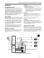
1
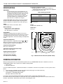
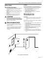
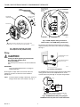
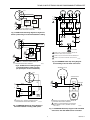
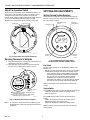
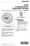
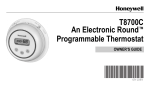
T8700B,C
An Electronic Round™
Programmable Thermostat
PRODUCT DATA
FEATURES
• Attractive neutral styling complements any decor.
• Easy-to-use means fewer homeowner questions and
increased homeowner satisfaction.
• Large easy-to-read display.
• Keys located near the display for easy access.
• Fan and System switches are located on the top of the
wallplate to eliminate accidental setting changes.
• Quick and easy installation.
Two-period programming for added energy savings.
• Manual changeover from heat to cool eliminates
unexpected system operation (T8700C).
• °F or °C temperature display for added model
flexibility.
T8700C
• Selectable heating cycle rate (1, 3, 6 or 9 cph) allows a
variety of applications and reduced inventory.
• Cooling (T8700C) cycle rate fixed at 3 cph (the standard
setting for compressors) allows a speedy installation.
APPLICATION
The T8700 Electronic Round™ Programmable Thermostats
provide single-stage, programmable temperature control for
24V heating and/or cooling systems. See Table 1 for model
descriptions.
Table 1. T8700 Thermostat Description.
• Programming permanently held in memory (no
batteries needed) and retained during power outages
for increased installer and homeowner convenience.
• Compatible with most equipment and application
needs including gas, oil and electric forced air;
condensing gas furnaces; hydronic heat; and gravity
and radiant heat systems.
System
Selection
Fan
Selection
Wiring
Terminals
Used
T8700B1007
HEAT-OFF
NONE
R,W
T8700B1015
HEAT-OFF
ON-AUTO
R,G,W
T8700C1005
HEAT-OFFCOOL
ON-AUTO
R,G,W,Y
Application ........................................................................... 1
Features .............................................................................. 1
Specifications ...................................................................... 2
Ordering Information ........................................................... 2
Installation ........................................................................... 3
Settings and Adjustments ................................................... 6
Setting the Clock ................................................................. 7
Programming ....................................................................... 7
Operation ............................................................................ 8
Checkout ............................................................................. 10
Troubleshooting ................................................................... 11
• All Rights Reserved
68-0197-1
Model
® U.S. Registered Trademark
Copyright © 1998 Honeywell Inc.
•
• Powerstealing eliminates need to run additional wires.
Contents
T8700B,C AN ELECTRONIC ROUND™ PROGRAMMABLE THERMOSTAT
Cycle Rates (at 50 Percent Load):
Heating: Selectable at 1, 3, 6 or 9 cph. See Table 2 for
heating cycle rates and corresponding system equipment.
Cooling (T8700C): Fixed at 3 cph.
SPECIFICATIONS
IMPORTANT
The specifications given in this publication do not
include normal manufacturing tolerances; therefore,
an individual unit might not exactly match the listed
specifications. Also, this product is tested and
calibrated under closely controlled conditions and
some minor differences in performance can be
expected if those conditions are changed.
Table 2. Heating Cycle Rates.
Cycles per
Hour (cph)
System
T8700 TRADELINE® models include a thermostat, wallplate,
decorator cover plate and owner’s guide. The package also
includes a resistor for use with Taco zone valves. See Fig. 11.
Power:
T8700: 24 Vac nominal, 18 to 30 Vac, 60 Hz.
Steam, Gravity
1
Hydronic Heat, Condensing Gas Furnaces
3
Gas or Oil Forced Air
6
Electric Furnace
9
Finish:
T8700: Premier White® color.
Electrical Ratings:
Heating: .02 to 1.2A run; 3.5A inrush.
Cooling: .02 to 1.2A run; 6.0A inrush.
Fan: .02 to 0.5A run; 2.5A inrush.
Dimensions:
See Fig. 1.
1-1/2
Current Draw:
T8700 Power Stealing Thermostat requires only 2.5 mA
current draw when the thermostat calls for heat or cool and is
compatible with most 24V systems. It can be used in most
non-millivolt applications. See Power Stealing in the Operation
section.
5-1/2
4-1/4
3-1/2
HE
O
FA
N
ON
TO
AU
CO
OL
Temperature Adjustment:
Setpoint temperature is adjusted by using the
or
keys.
One press changes the setpoint one degree; pressing and
holding changes the setpoint several degrees.
AT
FF
PM
Temperature Setting Range:
40°F (4°C) to 99°F (37°C).
Set
Operational Ambient Temperature Range:
30°F (4°C) to 110°F (43°C).
Shipping Temperature Range:
-20°F (29°C) to 120°F (49°C).
M12579
Operating Relative Humidity:
5% to 90% RH, noncondensing.
DECORATOR
COVER PLATE
T8700
THERMOSTAT
Fig. 1. T8700 Thermostat dimensions (T8700C shown).
ORDERING INFORMATION
When purchasing replacement and modernization products from your TRADELINE® wholesaler or distributor, refer to the
TRADELINE® Catalog or price sheets for the complete ordering number.
1. Order number.
2. Accessory, if desired.
If you have additional questions, need further information, or would like to comment on our products or services, please write or
phone:
1. Your local Home and Building Control Sales Office (check white pages of your phone directory).
2. Home and Building Control Customer Logistics
Honeywell Inc., 1985 Douglas Drive North
Minneapolis, Minnesota 55422-4386
In Canada—Honeywell Limited/Honeywell Limitée, 35 Dynamic Drive, Scarborough, Ontario M1V 4Z9.
International Sales and Service Offices in all principal cities of the world. Manufacturing in Australia, Canada, Finland, France,
Germany, Japan, Mexico, Netherlands, Spain, Taiwan, United Kingdom, U.S.A.
68-0197—1
2
T8700B,C AN ELECTRONIC ROUND PROGRAMMABLE THERMOSTAT
Location
INSTALLATION
Install the thermostat about 5 ft (1.5m) above the floor in an
area with good air circulation at average temperature. See
Fig. 2. Do not install the thermostat where it can be affected by:
— Drafts or dead spots behind doors and in corners.
— Hot or cold air from ducts.
— Radiant heat from the sun or appliances.
— Concealed pipes and chimneys.
— Unheated (uncooled) areas such as an outside wall
behind the thermostat.
When Installing this Product…
1. Read these instructions carefully. Failure to follow them
could damage the product or cause a hazardous
condition.
2. Check the ratings given in the instructions and on the
product to make sure the product is suitable for your
application.
3. Installer must be a trained, experienced service
technician.
4. After installation is complete, check out product
operation as provided in these instructions.
Mounting Decorator Cover
Plate and Wallplate to Wall
CAUTION
IMPORTANT
Position and level the wallplate for appearance only.
The thermostat functions properly even when not
level.
Damage To Heating/Cooling System Possible.
Be careful when handling wires during installation.
Disconnect power at furnace or at main breaker/fuse
box before starting installation.
Mount decorator cover plate (if desired), wallplate, T8700 and
the screws as follows; see Fig. 3:
RECYCLING NOTICE
1. Place the decorator cover plate and the wallplate on the
desired wall location.
2. Pull the thermostat wire through the entrance hole on
the decorator cover plate, then through the wallplate
entrance hole.
3. Plug the wiring hole behind the thermostat to prevent
drafts from affecting the thermostat.
4. Select the two mounting holes that best fit the
application.
5. Fasten the decorator cover plate and the wallplate to
the wall using the provided anchors (if necessary) and
screws.
If this control is replacing a control that contains
mercury in a sealed tube, do not place your old
control in the trash.
Contact your local waste management authority for
instructions regarding recycling and the proper
disposal of an old control containing mercury in a
sealed tube.
YES
NO
NO
5 FEET
[1.5 METERS]
NO
M12524
Fig. 2. Typical thermostat location.
3
68-0197—1
T8700B,C AN ELECTRONIC ROUND™ PROGRAMMABLE THERMOSTAT
ROUTE WIRING AS
SHOWN THROUGH
ENTRANCE
HOLE
WALL
ALTERNATE MOUNTING
SCREW HOLE
AT
HE
FA
N
PLASTIC SCREW
ANCHOR (2)
MOUNTING
SCREW
HOLE
TO
AU
DECORATOR
COVER PLATE
ON
CO
OL
FF
O
R
WALLPLATE
C
1
L
OO
O FF
G
H E AT
F
A
Y
N
N
O
TO
AU
W
ALTERNATE
MOUNTING
SCREW HOLE
MOUNTING
SCREW HOLE
WIRING ENTRANCE HOLE
M12529
Fig. 4. T8700C wallplate wiring connections.
(Refer to Table 1 for T8700B wiring connections.)
1
WHEN USING WALL ANCHORS, DRILL 3/16 INCH HOLES FOR
DRYWALL, 7/32 INCH HOLES FOR PLASTER OR WOOD.
The shape of the terminals permits insertion of straight or
wraparound wiring connections; either method is acceptable.
See Fig. 5.
M12532A
Fig. 3. Mounting decorator cover plate
and wallplate on wall (T8700C shown).
Wiring
CAUTION
FOR WRAPAROUND, STRIP
7/16 IN. (11 mm)
Damage To Heating/Cooling System Possible.
Be careful when handling wires
during installation.
Disconnect power at furnace or at main breaker/fuse
box.
FOR STRAIGHT INSERTION,
STRIP 5/16 IN. (8 mm)
M12537
IMPORTANT
Use an 18-gauge maximum wire for wiring the
T8700 Thermostat.
Fig. 5. Wiring connections.
All wiring must comply with local electrical codes and
ordinances. A letter is located near each terminal for
identification.
The T8700 Thermostat steals power through the heating and/or
cooling system controls and is adaptable to most, 24 Vac
systems. Refer to Fig. 6 through 11 for typical wiring hookups.
NOTE: To ensure proper mounting of thermostat, restrict all
wiring to the left side of the terminals. See Fig. 4.
T8700B
R
G
W
FAN
RELAY
1
L1
(HOT)
HEATING
PRIMARY
CONTROL
24V
L2
1
POWER SUPPLY. PROVIDE DISCONNECT MEANS AND
OVERLOAD PROTECTION AS REQUIRED.
M16005B
Fig. 6. T8700B1007 Heat Only wiring diagram
T8700B1015 Heat Only with Fan includes dotted line.
68-0197—1
4
T8700B,C AN ELECTRONIC ROUND PROGRAMMABLE THERMOSTAT
T8700
T8700
R
G
R
COOLING
CONTACTOR
Y
1
L1
(HOT)
R
T8700
R
W
W
L2
W
L1
(HOT)
FAN
RELAY
HEATING
PRIMARY
CONTROL
W
T8700
2
2
2
V8043E
V8043E
V8043E
3
3
3
1
24V
L2
1
POWER SUPPLY. PROVIDE DISCONNECT MEANS AND
OVERLOAD PROTECTION AS REQUIRED.
M13207
Fig. 7. T8700C heat-cool wiring diagram in single transformer system with gas or electric heat/electric cooling.
T
B1
T
T8700
R
1
TO
BURNER
CONTROL
CIRCUIT
B2
G
C1
2
COOLING
CONTACTOR
Y
C2
W
FAN
RELAY
CIRCULATOR
1
L1
(HOT)
1
L1
(HOT)
L2
T
1 POWER SUPPLY. PROVIDE DISCONNECT MEANS AND
OVERLOAD PROTECTION AS REQUIRED.
T
OIL PRIMARY
CONTROL
24V
2
CONNECT V8043E YELLOW LEADWIRE TO THERMOSTAT.
3
CONNECT V8043E RED LEADWIRES TO AQUASTAT®. M12623
L2
POWER SUPPLY. PROVIDE DISCONNECT MEANS AND
OVERLOAD PROTECTION AS REQUIRED.
1
Fig. 10. T8700B1007 Heat Only wiring diagram
for controlling 2-wire hot water zone valves.
M12526
Fig. 8. T8700C heat-cool wiring diagram
in oil heating/electric cooling system.
(Oil primary has its own transformer.)
THERMOSTAT T8700B
T8700
R
R
W
TACO ZONE VALVE
W
RED
1
L1
(HOT)
R841C
L2
1
L2
RESISTOR
1
2
2
WHITE
L1
(HOT)
BLACK
3
BLUE
RED
RESISTANCE
HEATER
1
BIMETAL
SWITCH
SWITCH
HEATER
POWER SUPPLY. PROVIDE DISCONNECT MEANS
AND OVERLOAD PROTECTION AS REQUIRED.
1
POWER SUPPLY. PROVIDE DISCONNECT MEANS AND
OVERLOAD PROTECTION AS REQUIRED.
2
CONNECT 7870 OHM RESISTOR TO THE TACO ZONE
VALVE TERMINALS 1 AND 2. (TO ORDER, USE PART
NO. 4074EYC.)
M12527B
Fig. 9. T8700B1007 Heat Only wiring diagram in
electric baseboard or ceiling cable system.
M13178
Fig. 11. T8700B1007 Heat Only diagram used with TACO
zone valves. The 7870 OHM resistor is included.
5
68-0197—1
T8700B,C AN ELECTRONIC ROUND™ PROGRAMMABLE THERMOSTAT
SETTINGS AND ADJUSTMENTS
Adjust Fan Operation Switch
The thermostat fan operation switch, labeled Fuel switch, is set
at the factory in the F position. See Fig. 12. This is the correct
setting for most systems. If this system is an electric heat
system, set the switch to the E position. The E setting allows the
fan to turn on immediately with the heating or cooling
equipment in a system where the G terminal is connected.
Setting Fan and System Switches
Fan and system settings are controlled manually using the
switches located at the top of the thermostat wallplate. See
Fig. 14 for switch locations.
FUEL SWITCH
CONNECTOR
1
SYSTEM SWITCH
E
F
TIME/TEMPERATURE
DISPLAY
AT
HE
FAN SWITCH
(SOME MODELS)
FA
N
ON
TO
AU
CO
OL
FF
O
PM
Set
1
T8700C AND T8700B WITH FAN ONLY.
M12531A
DECREASE
SETTING
Fig. 12. Fuel switch, rear view of thermostat.
INCREASE
SETTING
M12546A
Mounting Thermostat to Wallplate
Fig. 14. T8700 time/temperature display
and System/Fan switches (T8700C shown).
1. Align and attach bottom center notch on the thermostat
with bottom center tab on wallplate.
2. Next align tabs and connector at top of thermostat to
the pins on the wallplate. Press firmly to attach.
Fan Switch
The Fan switch settings for the T8700B1015 with Fan and
T8700C are:
ON: The fan runs continuously. Use to improve air circulation.
AUTO: Normal setting for most homes. In cooling, the fan
starts and stops with the cooling equipment. In heating,
the heating system directly controls the fan equipment.
The fan may start a few minutes after the heating
equipment turns on (for most systems). When the
thermostat Fuel switch is set to the E position for electric
heat, the fan starts and stops with heating equipment.
PINS
HE
AT
FA
N
ON
TO
AU
CO
OL
O
FF
Slide the Fan switch on the thermostat to the desired fan
setting.
Set
System Switch
BOTTOM CENTER
NOTCH
A
ALIGN AND ATTACH BOTTOM CENTER NOTCHS ON
THERMOSTAT/WALLPLATE.
B
ALIGN PINS ON WALLPLATE WITH CONNECTOR ON
THERMOSTAT. PRESS FIRMLY TO ATTACH.
The T8700B System switch controls the thermostat as follows:
HEAT: The thermostat controls the heating system.
OFF: Heating is off.
The T8700C System switch controls the thermostat as
follows:
COOL: The thermostat controls the cooling system.
OFF: Both heating and cooling are off.
HEAT: The thermostat controls the heating system.
M13208
Fig. 13. Mounting thermostat to wallplate.
NOTE: To remove the thermostat from the wallplate, grasp
the thermostat on both sides and pull the thermostat
straight out.
68-0197—1
Slide the System switch on the thermostat to the desired
system setting.
6
T8700B,C AN ELECTRONIC ROUND PROGRAMMABLE THERMOSTAT
2. Set your WAKE time.
SETTING THE CLOCK
a.
Press the
key
once. You will see a
flashing clock.
b.
Use the
c.
Press the
or
Press the
key
once. You will see a
flashing WAKE time.
b.
Use the
or
keys to set your desired WAKE
time. The WAKE time is now set.
M12507
PM
M12506
keys to set the current time.
3. Set your WAKE
temperature.
AM
PROGRAMMING
The thermostat is preprogrammed for your convenience with
the following time and temperature settings, see Table 3.
b.
Table 3. Preprogrammed Time/Temperature Settings.
Period
Start Time
Heating
Setpoint
WAKE
6:00 AM
70°F (21°C)
78°F (25.5°C)
SLEEP
10:00 PM
62°F (16.5°C)
82°F (28°C)
Cooling
Setpointa
a.
b.
WAKE is the time period when you want the house at a
comfortable temperature during the day.
SLEEP is the time period you can set for an energy-saving
temperature while you sleep.
M12508
Use the
or
keys to set your desired WAKE
temperature. The WAKE temperature is now set.
Press the
key
once. You will see a
flashing SLEEP time.
PM
M12509
Use the
or
keys to set your desired SLEEP
time. The SLEEP time is now set.
5. Set your SLEEP
temperature.
SET
PM
a.
NOTE: The heating and cooling program times are the
same. Changing your cooling WAKE time also
changes your heating WAKE time.
b.
The following is a heating program example. The System
switch is in the HEAT position. To change to the cooling
program (T8700C), move the System switch to the COOL
position and enter the cooling temperature settings.
Press the
key
once. You will see a
flashing SLEEP
temperature.
To program your own Time and Temperature settings
follow steps 1 through 6.
1. Set the current time.
M12510
Use the
or
keys to set your desired SLEEP
temperature. The SLEEP temperature is now set.
6. Run program.
a. Press the
key
once. You have
completed your
program changes.
End is displayed for
five seconds indicating the end of
programming. The
thermostat then
displays the current
time and room temperature.
IMPORTANT
When programming the T8700B, first move the
System switch to the heat position.
Press the
key
once. You will see a
flashing clock.
Press the
key
once. You will see a
flashing WAKE
temperature.
4. Set your SLEEP time.
a T8700C only.
b.
SET
key until End is displayed.
a.
a.
AM
a.
1. To set the current time:
M12511
PM
M12542
PM
NOTE: To exit the programming mode at any time, press the
key until End is displayed.
M12506
Use the
or
keys to set the current time. The
clock is now set.
Preprogrammed Time and Temperature settings.
After the clock is set, you can use the preprogrammed
Time and Temperature settings, (see table 3) press the
key until End is displayed.
The preprogrammed Temperature settings can now be
used.
7
68-0197—1
T8700B,C AN ELECTRONIC ROUND™ PROGRAMMABLE THERMOSTAT
2. Select Cycles Per Hour.
The display changes to
show current cycle
rate setting.
Operating the Thermostat
To Display Temperature
SET
Setting.
AM
Press
or
once to
display present temperature setting. After approxiM12512
mately five seconds, the
thermostat displays current time and room temperature.
To Make a Temporary
Temperature Change.
a. Press or
until
desired temperature
is displayed.
a.
Table 4. Heating Cycle Options
SET
AM
System
M12513
b.
TEMPORARY is
displayed. The
TEMPORARY
change is in effect
until the next
program period.
TEMPORARY
AM
Steam, Gravity
1
Hydronic Heat, Condensing Gas Furnaces
3
Gas or Oil Forced Air
6
Electric Heat
9
b.
To Use Hold Function.
To hold the thermostat at one temperature indefinitely,
program both WAKE and SLEEP to the same
temperature.
The following instructions provide the information necessary
to change the heating cycle rate, select either Fahrenheit
(F °) or Celsius (C °) and 12- or 24-hour clock format.
b.
b.
c.
68-0197—1
After the thermostat
reverts back to
displaying room
temperature
(approximately
five seconds),
simultaneously
press and
keys
and hold for three
seconds. Release
the keys after the
display changes.
Use
or
to
choose between °C
and °F.
M12521
4. Clock Format.
a. Press
to
display the current
12- or 24-hour clock
setting.
Installer Setup
1. Enter Installer Setup.
a. Use
or
keys
to set the
temperature setpoint to 52°F (11°C).
Program
Setting
(cph)
3. Select Fahrenheit - Celsius Temperature.
a. Press
to
display the current
°F or °C setting.
M12514
NOTE: To cancel your TEMPORARY change, press
until End is displayed.
NOTE: To exit at any time, press
M12520
Use
or
to
select 1, 3, 6, or 9 cph.
Refer to Table 4.
until End is displayed.
Use
or
to
choose either a 12- or 24-hour clock format.
Press
once to exit
Installer Setup. Upon
exiting, the temperature
setting will be at 52°F
(or 11°C). Press
six
times to return the
thermostat to the normal operating mode with End
appearing on the display.
SET
AM
M12518
TEMPORARY
AM
M12519
M12504
Press
within
five seconds.
8
M12522
M12511
T8700B,C AN ELECTRONIC ROUND PROGRAMMABLE THERMOSTAT
OPERATION
Fan Control
The FAN switch settings for the T8700B1015 with Fan and
T8700C are ON and AUTO.
ON: The fan runs continuously.
AUTO: In cooling, the fan starts and stops with the cooling
equipment. In heating, the fan starts a few minutes after
the heating equipment turns on. With the Fuel switch in
the E position for electric heat, the fan starts and stops
with the heating equipment.
Zero Droop Performance
The T8700 Thermostat can control temperature closer to
setpoint than electromechanical thermostats. This is because
proportional plus integral control (P + I) maintains a constant
indoor temperature independent of the outdoor temperature.
This feature allows the T8700 Thermostat to provide tight
temperature control with virtually no noticeable swings in
temperature, a condition referred to as droop. This zero droop
performance provides improved comfort and occupants do not
need to continually adjust thermostat settings to be
comfortable, even during extreme weather.
Heat Mode
With the T8700 system switch in the HEAT position, the
thermostat controls the heating system. On a call for heat, the
W terminal is energized and a flame icon
shows on the
digital display.
Power Stealing
If the Fuel switch is in the E position, both the W and G
terminals are energized on a call for heat.
The T8700 Thermostat steals power through the heating and/or
cooling system controls; therefore, it can be used in applications
where it is not possible to run additional wires. See Fig. 15.
Cool Mode
The T8700 Thermostat requires only 2.5 mA of load current
when the heating and/or cooling is on. When the heating and/or
cooling is off, the thermostat operates at 0.1 mA. This low
current draw allows the T8700C to be used with most 24V
heating and/or cooling systems.
With the T8700C System switch in the Cool position, the
thermostat controls the cooling system. On a call for cool,
the G and Y terminals are energized and a snowflake icon
shows on the digital display. A flashing snowflake indicates
that the minimum-off timer is in effect.
The T8700 Thermostat operates only when mounted on the
wallplate with 24V applied. Batteries are not required for
operation. Temperature setpoints, programming and
configuration settings are retained permanently in memory.
Minimum Off-Timer T8700C
A minimum off-timer for the T8700C assures that the cooling
compressor does not come on again for at least five minutes
after it turns off. The minimum-off timer is triggered when the
compressor turns off or when the System switch is changed.
If the compressor turns off when the setpoint is changed, the
minimum-off timer is triggered. Power interruption and power
restoration also trigger the minimum off-timer.
Sequence of Operations
The Heat and Cool outputs are transistor controlled. A loss of ac
power or a change in the System switch setting can turn off
outputs. Table 5 shows the Fan and System sequence of
operations.
L1
(HOT) L2
1
R
FAN SWITCH
FAN RELAY
ON
G
THERMISTOR
SENSOR
THERMOSTAT
LOGIC
AUTO
HEAT RELAY
SYSTEM SWITCH
W
HEAT
OFF
COOL RELAY
COOL
Y
POWER
SUPPLY
LOGIC AND
CONTROL
MOSFET
1
POWER SUPPLY. PROVIDE DISCONNECT MEANS AND
OVERLOAD PROTECTION AS REQUIRED.
MOSFET
M10360
Fig. 15. T8700C power stealing internal schematic.
9
68-0197—1
T8700B,C AN ELECTRONIC ROUND™ PROGRAMMABLE THERMOSTAT
Table 5. Sequence of Operations.
Fan Switch Settings
System Switch Settings
Call for Action
Energize Terminals
Display Icons
AUTO
OFF
None
None
None
ON
Any
Any
G
None
AUTO
COOL b
Cooling b
G, Y
AUTO
HEAT
Heating
W,Ga
a When fuel switch is in the E position. (T8700B with Fan and T8700C).
b T8700C only.
IMPORTANT
A mimimum off-timer for the T8700C assures that the
cooling compressor does not come on again for at
least five minutes after it turns off. The minimum-off
timer is triggered when the compressor turns off or
when the System switch is changed. If the compressor
turns off when the setpoint is changed, the minimumoff timer is triggered. Power interruption and power
restoration also trigger the minimum off-timer.
CHECKOUT
Heating (T8700B,C)
1. Slide the System switch to HEAT and the Fan switch to
AUTO. (For T8700B1007 Heat Only model, a Fan switch
is not an option).
2. Press and hold the
key to raise the temperature
setting several degrees above the room temperature
the heating equipment should start. In conventional
systems, the system turns on the fan through a limit
control. When using the thermostat with the fuel switch
set to the E position for electric heat, the fan starts
immediately.
3. Press the
key to lower the temperature setting below
the room temperature. Heating equipment should stop.
1. Slide the System switch to COOL and the Fan switch to
AUTO.
2. To start the cooling equipment, press the
key to
lower the temperature setting several degrees below
room temperature. The fan starts and stops with the
cooling equipment.
3. Press the
key to raise the temperature setting above
the room temperature. Cooling system should shut down.
Cooling (T8700C)
Fan (T8700B1015 with Fan, T8700C)
CAUTION
1. Slide the System switch to OFF and the Fan switch to
ON. The Fan should run continuously.
2. Slide the Fan switch to AUTO. In heating, the fan is
controlled directly by the heating equipment and starts
a few minutes after the heating equipment turns on (for
most systems). When using the thermostat with the
Fuel switch set to the E position for electric heat, the fan
starts and stops with the heating equipment. In cooling,
the fan starts and stops with the cooling equipment.
Equipment Damage Possible.
Operating at too low of an outdoor temperature
can cause compressor damage.
Do not attempt to operate cooling when outdoor
temperature is below 50°F (10°C). Refer to
manufacturer recommendations.
Make certain all equipment responds properly to the
thermostat.
68-0197—1
10
T8700B,C AN ELECTRONIC ROUND PROGRAMMABLE THERMOSTAT
TROUBLESHOOTING
Symptom
Heating/cooling
equipment does not
operate.
Possible Cause
No ac power.
Corrective Action
Check power to heating/cooling equipment:
— On/Off switch.
— Fuse or circuit breaker.
— Loose 24V connection: at thermostat; at furnace/air
conditioner.
— Incorrect wiring: check appropriate wiring diagram.
Thermostat inoperative.
See Checkout section.
Incorrect wiring.
Check wiring.
Heating/cooling equipment
inoperative.
Consult equipment manufacturer instructions.
System switch on thermostat in
wrong position.
Reset System switch.
Flashing
Snowflake
Minimum-off timer in thermostat
operating for cooling.
Wait five minutes or follow steps in Checkout section.
Partial display.
Still in installer setup mode.
See Installer Setup section for instructions on how to exit.
Damaged thermostat.
Replace thermostat.
Displaying only time
and not temperature.
Power to thermostat is currently
interrupted.
Check the power to thermostat.
Blank display.
No power to thermostat.
Check the power to thermostat.
Thermostat mounted incorrectly on
wallplate.
See installation instructions for correct mounting.
Temperature display
is incorrect.
Thermostat is configured
incorrectly for °F or °C.
Reconfigure display. See Installer Set-up for instructions to
change display.
Cannot change
temperature setting.
Upper or lower temperature
setpoints were reached.
Check temperature setpoints; temperature setting range is
40°F (4°C) to 99°F (37°C).
Time loss.
Power to thermostat was
interrupted longer than 20
minutes.
Reset clock. See Setting The Clock
11
68-0197—1
T8700B,C AN ELECTRONIC ROUND™ PROGRAMMABLE THERMOSTAT
Home and Building Control
Honeywell Inc.
Honeywell Plaza
P.O. Box 524
Minneapolis MN 55408-0524
Home and Building Control
Honeywell Limited-Honeywell Limitée
155 Gordon Baker Road
North York, Ontario
M2H 3N7
Honeywell Latin American Region
480 Sawgrass Corporate Parkway
Suite 200
Sunrise FL 33325
Honeywell Europe S.A.
3 Avenue du Bourget
1140 Brussels
Belgium
68-0197—1 D.S. Rev. 7-98
68-0197—1
Printed in U.S.A. on recycled
paper containing at least 10%
post-consumer
12 paper fibers.
Honeywell Asia Pacific Inc.
Room 3213-3225
Sun Hung Kai Centre
No. 30 Harbour Road
Wanchai
Hong Kong
www.honeywell.com/yourhome