1
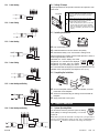
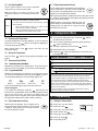
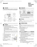
RTH230B
q
Wrap the wires around a pencil to prevent
them from falling into the wall.
Programmable Electronic Thermostat
r
If the hole in the wall is too big, insulate it
using a non-flammable material in order to
avoid air draughts behind the thermostat.
Installation and User Guide
2.2 Installing the New Baseplate
1. Introduction
The RTH230B programmable thermostat can be used to control:
• a gas, fuel oil or electric furnace - 2 or 3 wires
• a central air conditioner - 2 or 3 wires
For a new installation, choose a location approximately 5 feet
(1.5 m) above the floor and on an inside wall. Avoid draughty
areas (top of staircase, air outlet, etc.), dead air spots (behind
doors), direct sunlight or areas near concealed pipes or chimneys.
• a hot water system with or without pump - 2 wires
• a millivolt system - 2 wires
• a central heating and cooling system - 4 or 5 wires
Note: These thermostats are not compatible with heat pumps or
multi-stage systems.
Display
System operating
mode selector
Fan operating
mode selector
Adjustment
buttons
Remove the thermostat faceplate.
p
q
Tilt the thermostat upwards.
r
Pass the wires through the opening of the baseplate and fix the
baseplate to the wall using the screws provided.
Loosen the locking screw to separate the thermostat from its
baseplate (the screw cannot be completely removed).
Programming
buttons
Features
• System operating mode selection: heat, cool or off
• Fan operating mode selection: automatic or on (continuous)
• Programmable heating and cooling cycle lengths: 10, 12, 15, 20
or 30 minutes
• Temperature display in °F or °C
• Battery replacement indicator
• 5-2 programming including:
- Preprogrammed energy-saving schedule
- Early Start
- Temporary bypass
- Time display (12 h or 24 h)
• Filter replacement indicator
2. Installation
2.1 Removing the Old Thermostat
IN ORDER TO AVOID ANY RISK OF ELECTRIC SHOCK, CUT
POWER TO THE HEATING SYSTEM.
n
n
o
Remove the old thermostat to access the wires.
Mark and bore the appropriate mounting holes (or use the
existing holes). Insert the plastic anchors.
2.3 Connecting the Thermostat
The connection of the new thermostat should be similar to that of
the old thermostat; however, it can vary depending on the installation.
Rh
Heating power supply
Rc
Cooling power supply
W
Heating signal
Y
Cooling signal
G
Fan
Note: The red jumper wire between the Rc and Rh terminals must
be removed in 2- or 5-wire installations. The jumper must be used in
3- or 4-wire installations if you wish to use the mode selector switch
for the fan.
Warning: If the old thermostat was mounted onto an electrical box,
it was probably powered by 120/240 volts. In this case, this thermostat cannot be used.
o
Identify and label each wire (with the corresponding letter on
the wire terminal) and remove them from the terminals.
p
If necessary, strip the end of each wire (maximum of 1/4 inch).
RTH230B
69-1800-01
69-1800-01
11/09
1/4
2.4 Setting J2 Jumper
2.3.1 2-wire Heating
The jumper defines the fan operation when the fan is placed in automatic mode.
J2 jumper
HE
Use this setting if you have an electric furnace. In
this setting, when the fan is placed in automatic
mode, it works only when heating or cooling is
activated.
HG
Use this setting if you have a gas or fuel oil furnace. In this setting, when the fan is placed in
automatic mode, it works as follows:
• When the thermostat is placed in cool mode,
the fan works only when cooling is activated.
• When the thermostat is placed in heat mode,
the fan is controlled by the furnace fan control
circuitry.
Heat relay
2.3.2 2-wire Cooling
2.5 Installing the Batteries
Cool relay
2.3.3 3-wire Heating
n
o
p
Heat relay
Fan relay
Pull out the battery cover.
Install the batteries as shown. Observe the polarity.
Reinstall the battery cover. You will hear a clicking sound.
After the batteries are installed, the thermostat performs a series of
tests for approximately 5 seconds.
Afterwards, the screen displays the actual
temperature. It is normal that the displayed
temperature be higher than the ambient
temperature if you are holding the thermostat. The thermostat will display the ambient temperature once it is
installed on the wall. By default, the setpoint is 70°F (21°C).
2.3.4 3-wire Cooling
2.6 Completing the Installation
Cool relay
Fan relay
2.3.5 4-wire Heating and Cooling
n
Once the baseplate and the batteries are installed, mount the
thermostat on the baseplate.
o
Secure the thermostat using the locking screw and install the
faceplate.
p
Apply power back to the system.
Heat relay
Cool relay
Fan relay
3. Basic Functions
3.1 System Operating Mode
2.3.6 5-wire Heating and Cooling
Use the selector switch to place the system in Heating
mode (HEAT) or Cooling mode (COOL), or to set the
system off.
Fan relay
Heat relay
RTH230B
Note: When you place the thermostat in Cooling mode, you might need to
wait up to five minutes before cooling can start. This is a safety feature for
the compressor.
will flash on the screen until cooling can start again.
Cool relay
69-1800-01
11/09
2/4
3.2 Fan Operating Mode
3.7 Battery Replacement Indicator
Use the selector switch to set the fan to automatic
mode (AUTO) or continuous mode (ON).
An icon appears when the batteries need replacement.
This icon will flash for 120 days, then the thermostat
will cut power to the heating/cooling unit. The icon disappears once the batteries are replaced.
Note: This switch is not used if you have a 2-wire
installation as the fan is not connected to the thermostat.
AUTO
•
If you have an electric furnace (see section 2.4), the fan
works only when heating or cooling is activated.
•
If you have a gas or fuel oil furnace (see section 2.4), the fan
works as follows:
•
•
ON
When the thermostat is placed in cool mode, the fan
works only when cooling is activated.
When the thermostat is placed in heat mode, the fan is
controlled by the furnace fan control circuitry.
The fan is always on.
3.3 Displaying the Temperature
The actual temperature is normally displayed. To view the setpoint,
press once on one of the
buttons. The setpoint is displayed for
5 seconds along with the icon.
Note: Pressing either of the
change the setpoint.
buttons more than once will
3.4 Setting the Temperature
Press one of the
played.
buttons until the desired temperature is dis-
After replacing the batteries, readjust the time and day (see section
5.1). However, the temperature and program settings are saved and
do not need to be re-entered.
Warning: Before removing the batteries, place the
system switch on the thermostat to Off. Otherwise, the
heating/cooling unit might still be running even after
the batteries are removed.
4. Configuration Menu
n
To access the configuration menu, press both
simultaneously for 3 seconds.
o
To go to the next parameter (menu item), briefly press both
buttons simultaneously.
p
q
r
To modify a parameter, press one of the
Press both
buttons simultaneously for 3 seconds to exit
the configuration menu.
DESCRIPTION
DEFAULT
OPTIONS
°F
°C or °F
Time display
12 h
12 h or 24 h
Early Start 1
Off
On or Off
Heating cycles per hour 2
4
2, 3, 4, 5 or 6 3
Cooling cycles per hour 2
4
2, 3, 4, 5 or 6 4
Temperature display
3.5.1 Manual/Permanent Hold Mode
Maintains the temperature at a fixed setpoint. To place the thermostat in this mode, press [ Mode ]. The house icon will disappear.
3.5.2 Programmable Mode
Maintains the temperature according to the energy-saving schedule. To place the thermostat in this mode, press [ Mode ]. The current period will be displayed. The four possible periods are:
buttons.
Repeat steps 2 and 3 if necessary.
DISPLAY
3.5 Thermostat Control Mode
buttons
1
When Early Start is On, the thermostat determines when to start heating
or cooling so that the desired temperature is reached at the set time.
2
When either the heating or cooling parameter is displayed, use the system mode selector switch to alternate between the two parameters.
3
Wake up
Leave for work
Return home
Sleep
To see the default settings of each period, see section 5.2.
Temporary Bypass
If you modify the temperature (using the
buttons) when the
thermostat is in programmable mode, the new temperature will be
used for the next 2 hours. The house icon flashes during the
bypass. At the end of the bypass period, the thermostat returns to
the temperature settings of the period currently underway.
For optimal heating control, use the setting that matches your system as
follows: 2=30 min (steam, gravity), 3=20 min (hot water, 90%+ high-efficiency furnace), 4=15 min (gas or oil), 5=12 min (alternate setting for gas
or oil), 6=10 min (electric).
4
The corresponding cooling cycle lengths are as follows: 2=30 min,
3=20 min, 4=15 min, 5=12 min, 6=10 min
5. Programming
3.6 Filter Replacement Indicator
5.1 Setting the Time and Day
After 500 hours of operation, an icon appears to indicate that the filter needs replacement. Once the filter
is replaced, press [ Filter ] for 3 seconds to remove
the icon and reset the counter.
n
o
p
q
r
s
t
RTH230B
Press [ Clk ]. The hour flashes.
Set the hour using
.
Press [ Clk ]. The minutes flash.
Set the minutes using
.
Press [ Clk ]. The day flashes.
Set the day using
.
Press [ Exit ] to exit.
69-1800-01
11/09
3/4
5.2 Energy-saving Schedule
Your thermostat is preprogrammed with an energy-saving schedule.
The schedule automatically controls your heating or cooling system
by switching from one setpoint to the next according to the preset
times.
Default schedule settings
Heating
70°F (21°C)
Cooling
78°F (25.5°C)
Heating
62°F (16.5°C)
Cooling
85°F (29.5°C)
Heating
70°F (21°C)
Cooling
78°F (25.5°C)
Heating
62°F (16.5°C)
Cooling
82°F (28°C)
Monday
to Friday
Saturday
& Sunday
6:00 a.m.
6:00 a.m.
8:00 a.m.
--
6:00 p.m.
--
10:00 p.m.
10:00 p.m.
5.3 Modifying the Schedule
You can program up to 4 periods per day, each period having its
own temperature settings. The same program is repeated daily from
Monday through Friday and another program is used for Saturday
and Sunday. For each period, you can set the start time, the heating
setpoint and the cooling setpoint.
Press [ Pgm ]. The settings for period 1 are displayed.
Period start time
Temperature
setting
Program days
Period number
Note: During programming, to skip a period, press [ CLR ] while
the period is displayed. For example, in the predefined energy-saving schedule, periods 2 and 3 have been skipped for Saturday and
Sunday.
o
Select the program using the [ Day ] button (MO TU WE TH FR
appears when the Monday-Friday program is selected or SA
SU appears when the Saturday/Sunday program is selected).
Press for 3 seconds to select all 7 days.
p
Set the time (in increments of 15 minutes) using the
tons.
q
Press [ P# ]. The heating or cooling setpoint
flashes depending on the position of the Heat/
Cool selector.
r
Set the desired temperature for the displayed
period using the
buttons.
s
Use the Heat/Cool selector to switch to the other mode (e.g., if
you were in Heating mode, switch to Cooling mode). The setpoint for that mode flashes.
t
u
v
w
Set the desired temperature using the
Power supply: 2 AA batteries
Maximum load: 1 A @ 24 Vca per output
Setpoint range (heating): 41 to 82°F (5 to 28°C)
Setpoint range (cooling): 59 to 95°F (15 to 35°C)
Display range: 23 to 122°F (-5 to 50°C)
Storage temperature: -2 to 122°F (-20 to 50°C)
Temperature display resolution: 1°F (0.5°C)
Accuracy: ± 1°F (0.5°C)
Heating/cooling cycle lengths: 10, 12, 15, 20 or 30 minutes (programmable)
Compressor short-cycle protection (minimum off time): 5 minutes
Data memory: non-volatile
Dimensions: 5 in. x 3 in. x 1 in. (127 mm x 75 mm x 28 mm)
7. Warranty
Note: To use the schedule, place the thermostat in programmable
mode.
n
6. Technical Specifications
but-
buttons.
Honeywell warrants this product, excluding battery, to be free from defects in
the workmanship or materials, under normal use and service, for a period of
one (1) year from the date of purchase by the consumer. If at any time during the warranty period the product is determined to be defective or malfunctions, Honeywell shall repair or replace it (at Honeywell's option).
If the product is defective,
(i) return it, with a bill of sale or other dated proof of purchase, to the place
from which you purchased it, or
(ii) call Honeywell Customer Care at 1-800-468-1502. Customer Care will
make the determination whether the product should be returned to the
following address: Honeywell Return Goods, Dock 4 MN10-3860,
1885 Douglas Dr N, Golden Valley, MN 55422, or whether a replacement product can be sent to you.
This warranty does not cover removal or reinstallation costs. This warranty
shall not apply if it is shown by Honeywell that the defect or malfunction was
caused by damage which occurred while the product was in the possession
of a consumer.
Honeywell's sole responsibility shall be to repair or replace the product
within the terms stated above. HONEYWELL SHALL NOT BE LIABLE FOR
ANY LOSS OR DAMAGE OF ANY KIND, INCLUDING ANY INCIDENTAL
OR CONSEQUENTIAL DAMAGES RESULTING, DIRECTLY OR INDIRECTLY, FROM ANY BREACH OF ANY WARRANTY, EXPRESS OR
IMPLIED, OR ANY OTHER FAILURE OF THIS PRODUCT. Some states do
not allow the exclusion or limitation of incidental or consequential damages,
so this limitation may not apply to you.
THIS WARRANTY IS THE ONLY EXPRESS WARRANTY HONEYWELL
MAKES ON THIS PRODUCT. THE DURATION OF ANY IMPLIED WARRANTIES, INCLUDING THE WARRANTIES OF MERCHANTABILITY AND
FITNESS FOR A PARTICULAR PURPOSE, IS HEREBY LIMITED TO THE
ONE-YEAR DURATION OF THIS WARRANTY. Some states do not allow
limitations on how long an implied warranty lasts, so the above limitation
may not apply to you.
This warranty gives you specific legal rights, and you may have other rights
which vary from state to state.
If you have any questions concerning this warranty, please write Honeywell
Customer Relations, 1985 Douglas Dr, Golden Valley, MN 55422 or call 1800-468-1502. In Canada, write Retail Products ON15-02H, Honeywell Limited/Honeywell Limitée, 35 Dynamic Drive, Scarborough, Ontario M1V4Z9.
8. Customer Assistance
If you have any questions about the operation of your thermostat, please go
to www.honeywell.com/yourhome, or call Honeywell Customer Care tollfree at 1-800-468-1502.
Press [ P# ] to go to the next period.
Repeat steps 2 to 8 for each of the remaining periods.
Press [ Exit ] to exit.
Note: To use the schedule, place the thermostat in programmable
mode.
Printed in USA
RTH230B
®
As an ENERGY STAR partner, Honeywell has determined that this
product meets the ENERGY STAR guidelines for energy efficiency.
69-1800-01
11/09
4/4