1
Airport Systems
Installation and Operation Guide
for
High Intensity Obstruction
Lighting System
Model SG-60
Manual Number EPM-00000019-001
Honeywell Airport Systems
2162 Union Place
Simi Valley, CA 93065
Phone (805) 581-5591
Fax (805) 581-5032
www.oblighting.com
Copyright 2002 Honeywell Inc.
All Rights Reserved
Airport Systems
HISTORY OF REVISIONS
Rev.
A
Comment
First Release (New Boards)
ECO#
3637
Approved
S. Hammond
Date
8/30/2002
NOTICE
The integrity and reliability of Honeywell airport lighting systems are dependent on the use
of Honeywell parts and components. To ensure the optimum performance and reliability of
your Honeywell system, it is strongly advised that only components and modules provided
by Honeywell be used.
WARRANTY
Honeywell warrants the equipment described in this instruction manual and sold to
the purchaser to be free from defects in material and workmanship at the time of shipment.
Honeywell’s liability under this warranty being limited to repairing or replacing, at
Honeywell’s option, items which are returned to it prepaid within one year from date of
installation or a maximum of two years from date of shipment (whichever is less) to the
original Purchaser and found, to Honeywell’s satisfaction, to have been defective. In no
event shall Honeywell be liable for consequential damages. NO PRODUCT IS
WARRANTED AS BEING FIT FOR A PARTICULAR PURPOSE AND THERE IS NO
WARRANTY OF MERCHANTABILITY. This warranty applies only if: (I) the items are
used solely under the operating conditions and in the manner recommended in Honeywell’s
instruction manual, specifications, or other literature; (II) the items have not been misused
or abused in any manner or repairs attempted thereon; (III) written notice of the failure
within the warranty period is forwarded to Honeywell and the directions received for
properly identifying items returned under warranty are followed; and (IV) such return notice
authorizes Honeywell to examine and disassemble returned products to the extent
Honeywell deems necessary to ascertain the cause of failure. The warranties stated herein
are exclusive. THERE ARE NO OTHER WARRANTIES, EITHER EXPRESSED OR
IMPLIED, BEYOND THOSE SET FORTH HEREIN, and Honeywell does not assume, nor
does Honeywell authorize anyone else to assume for it, any other obligation or liability in
connection with the sale or use of said products. Honeywell’s liability on any claim of any
kind, including negligence, for loss or damages arising out of or connected with the
manufacture, sale, delivery, repair or use of any equipment or services provided by
Honeywell shall in no case exceed the price allocable to the item or service or part thereof
which gives rise to the claim.
EPM-00000019-001
i
Rev A
Airport Systems
DISCLAIMERS
This manual could contain technical inaccuracies or typographical errors. Honeywell
reserves the right to revise this manual from time to time of the contents thereof without
obligation of Honeywell to notify any person of such revision or change. Details and
values given in this manual are average values and have been compiled with care.
They are not binding, however, and Honeywell disclaims any liability for damages or
detriments suffered as a result of reliance on the information given herein or the use of
product, processes or equipment to which this manual refers. No warranty is made that
the use of the information or of the products processes or equipment to which this
manual refers will not infringe any third party’s patents or rights. The information given
does not release the buyers from making their own experiments and tests.
EPM-00000019-001
ii
Rev A
Airport Systems
TABLE OF CONTENTS
SAFETY INFORMATION ............................................................................................... V
SECTION 1. GENERAL INFORMATION .....................................................................1-1
1.1 SCOPE ......................................................................................................................................1-1
1.2 GENERAL DESCRIPTION ..............................................................................................................1-1
1.2.1 Model SGC-60 Master Controller .....................................................................................1-1
1.2.2 Model SGF-60 Flashhead ................................................................................................1-1
1.2.3 Ambient Light Sensor (P/N 12H00107-001).......................................................................1-1
1.3 SAFETY PRECAUTIONS ................................................................................................................1-4
1.4 SPECIFICATIONS .........................................................................................................................1-6
SECTION 2. INSTALLATION & POWER UP...............................................................2-1
2.1 UNPACKING ...............................................................................................................................2-1
2.2 SYSTEM CONFIGURATION..............................................................................................................2-1
2.2.1 Master Controller Configuration .......................................................................................2-1
2.2.2 Flashhead Configuration ..................................................................................................2-3
2.3 INSTALLATION ............................................................................................................................2-6
2.3.1 SGC-60 Master Controller...............................................................................................2-6
2.3.2 SGF-60 Flashhead...........................................................................................................2-6
2.3.3 Ambient Light Sensor (Photocell).....................................................................................2-7
2.3.4 Cables and Junction Boxes..............................................................................................2-8
2.4 INSTALLATION W IRING ..............................................................................................................2-11
2.4.1 Master Controller to Photocell Wiring.............................................................................2-12
2.4.2 Master Controller Data/Communications Wiring.............................................................2-12
2.4.3 Master Controller Power Wiring .....................................................................................2-12
2.4.4 Master Controller Wiring For Dual Systems ...................................................................2-13
2.4.5 Flashhead Wiring...........................................................................................................2-14
2.4.6 Conduit and Tower Wiring Detail ...................................................................................2-14
2.4.7 Junction Box Details ......................................................................................................2-18
2.5 FINAL INSTALLATION CHECK ......................................................................................................2-27
2.5.1 Preliminary ....................................................................................................................2-27
2.5.2 Verify Correct Wiring in Master Controller......................................................................2-27
2.5.3 Verifying Photocell Wiring..............................................................................................2-27
2.5.4 Verify Proper Tower Wiring for Data/Control Cable........................................................2-27
2.6 POWER UP AND SYSTEM TESTS .................................................................................................2-28
2.6.1 Master Controller Status Indicators ................................................................................2-28
2.6.2 Flashhead Status Indicators...........................................................................................2-29
2.6.3 System Power Up ..........................................................................................................2-29
2.6.4 Verify Local Mode Operation..........................................................................................2-30
2.6.5 Verify Photocell Operation Connected to Controller .......................................................2-33
2.6.6 Verify Photocell Operation Not Connected to Controller.................................................2-33
SECTION 3. PRINCIPLES OF OPERATION ...............................................................3-1
3.1 OVERALL DESCRIPTION ...............................................................................................................3-1
3.2 SGF-60 FLASHHEAD ..................................................................................................................3-1
3.2.1 SGF-60 Motherboard .......................................................................................................3-3
3.2.2 SGF-60 Digital Board.......................................................................................................3-3
3.2.3 SGF-60 Trigger/High-Voltage Board ................................................................................3-6
3.3 SGC-60 MASTER CONTROLLER ..................................................................................................3-8
3.3.1 Power Supply...................................................................................................................3-8
3.3.2 Flash Requests and Flashhead Status .............................................................................3-8
3.3.3 System Mode Selection ...................................................................................................3-9
EPM-00000019-001
iii
Rev A
Airport Systems
3.3.4
Communications Circuitry ..............................................................................................3-10
SECTION 4. TROUBLESHOOTING ............................................................................4-1
SECTION 5. MAINTENANCE ......................................................................................5-1
5.1 SGC-60 MASTER CONTROLLER ..................................................................................................5-1
Transformer Replacement............................................................................................................5-1
5.2 SGF-60 FLASHHEAD ..................................................................................................................5-2
5.2.1 Flashtube Replacement ...................................................................................................5-2
5.3 AMBIENT LIGHT SENSOR (PHOTOCELL) .........................................................................................5-3
SECTION 6. REPLACEMENT PARTS ........................................................................6-1
SECTION 7. ANTENNA OBSTRUCTION LIGHT (AOL) .............................................7-1
TABLE OF FIGURES
Figure 1-1: Model SGC-60 Master Controller...............................................................1-2
Figure 1-2: Model SGF-60 Flashhead..........................................................................1-3
Figure 2-1: Flashtube Installation.................................................................................2-6
Figure 2-2: Master Controller Mounting Dimensions....................................................2-9
Figure 2-3: Flashhead Outline and Mounting Dimensions ............................................2-10
Figure 2-4: Typical Wiring Installation..........................................................................2-11
Figure 2-5: Flex Conduit Typical Installation Layout ..................................................2-15
Figure 2-6: Junction Box Wiring Details .....................................................................2-19
Figure 2-7: Flex Conduit Installation Detail ................................................................2-20
Figure 2-8: WC000001 Cable Overview ....................................................................2-21
Figure 2-9: Flashhead Cable.......................................................................................2-24
Figure 2-10: Master Controller Circuit Board .............................................................2-25
Figure 2-11: Flashhead Digital Control Board............................................................2-26
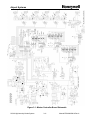
Figure 3-1: Master Controller Board Schematic .........................................................3-11
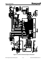
Figure 3-2: SGF-60 Flashhead System Schematic ....................................................3-12
Figure 3-3: SGF-60 Digital Board Schematic .............................................................3-13
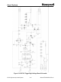
Figure 3-4: SGF-60 Trigger/High-Voltage Board Schematic......................................3-14
Figure 4-1: General Troubleshooting – All Flashheads Stuck in Day Mode ................4-3
Figure 4-2: General Troubleshooting – Flashhead Does Not Flash.............................4-4
Figure 4-3: General Troubleshooting – Flashhead Stuck in Day Mode .......................4-5
Figure 4-4: Dual System-Specific Troubleshooting ......................................................4-6
Figure 4-5: Catenary System-Specific Troubleshooting Chart .....................................4-7
Figure 5-1: SGC-60 Replacement Transformer ...........................................................5-1
Figure 5-2: Flashtube Installation.................................................................................5-3
Figure 7-1: SG-60 AOL Flashhead Mounting Dimensions ...........................................7-2
Figure 7-2: SG-60 AOL Power Supply Mounting Dimensions ......................................7-3
Figure 7-3: SG-60 AOL Wiring Installation...................................................................7-4
Figure 7-4: SG-60 AOL Flashhead Component Locations...........................................7-5
Figure 7-5: SG-60 AOL Power Supply Component Locations......................................7-6
Figure 7-6: SG-60 AOL Schematic...............................................................................7-7
EPM-00000019-001
iv
Rev A
Airport Systems
SAFETY INFORMATION
This section contains general safety instructions for using your Honeywell equipment. Task
and equipment-specific Warnings are included in other sections of this manual where
appropriate. Read all Warnings and follow all instructions carefully. Failure to do so may
result in personal injury, death, or property damage. To use this equipment safely, refer to
the following:
1.
Refer to the FAA Advisory Circular AC 150/5340-26, Maintenance of Airport Visual
Aids Facilities, for instructions on safety precautions.
2.
Observe all safety regulations. To avoid injuries, always remove power prior to making
any wire connections and/or touching any parts. Refer to FAA Advisory Circular AC
150/5340-26.
3.
Read and become familiar with the general safety instructions provided in this section
of the manual before installing, operating, maintaining, or repairing this equipment.
4.
Read and carefully follow the instructions given throughout this manual before
performing specific tasks and working with specific equipment.
5.
Store this manual within easy reach of personnel installing, operating, maintaining, or
repairing this equipment.
6.
Follow all applicable safety procedures required by your company, industry standards,
and government or other regulatory agencies.
7.
Obtain and read Material Safety Data Sheets (MSDS) for all materials used.
SAFETY AND WORKMANSHIP ALERTS
This manual uses two types of markings when giving instructions requiring special
attention. The markings will be followed by indented text:
WARNING!
The WARNING sign in this manual denotes a hazard. The WARNING
calls attention to a procedure or practice which, if not correctly
performed or adhered to, could result in property damage, injury or
death. Do not proceed beyond a WARNING sign until the indicated
conditions are fully understood and met.
.
CAUTION
Failure to obey the instructions following a CAUTION marking may
result in equipment damage.
EPM-00000019-001
v
Rev A
Airport Systems
QUALIFIED PERSONNEL
The term “qualified personnel” is defined here as individuals who thoroughly
understand the equipment and its safe operation, maintenance, and repair. Qualified
personnel are physically capable of performing the required tasks, familiar with all
relevant safety rules and regulations and have been trained to safely install, operate,
maintain, and repair the equipment. It is the responsibility of the company operating
this equipment to see that its personnel meet these requirements.
INTERLOCKS
This equipment contains interlocks for your protection. To ensure safety, always
remove power from the equipment prior to opening access panels or doors if possible.
Do not depend on the interlocks or door switches when working with the equipment.
Do not short-circuit or tamper with any access gate, door or other safety interlock
switch. Discharge capacitors with an approved insulated grounding rod prior to
touching any part. When it is absolutely mandatory that an interlock be bypassed for
the purpose of tracing or correcting a malfunction, authorized maintenance personnel
may perform the bypass for the specific test to be made. Immediately after completing
the test, restore the interlock to working condition.
WARNING!
INTENDED USE
HONEYWELL IS NOT RESPONSIBLE FOR INJURIES OR DAMAGES
RESULTING FROM NONSTANDARD, UNINTENDED APPLICATIONS OF
ITS EQUIPMENT. THIS EQUIPMENT IS DESIGNED AND INTENDED
ONLY FOR THE PURPOSE DESCRIBED IN THIS MANUAL. USES NOT
DESCRIBED IN THIS MANUAL ARE CONSIDERED UNINTENDED USES
AND MAY RESULT IN SERIOUS PERSONAL INJURY, DEATH OR
PROPERTY DAMAGE. UNINTENDED USES MAY RESULT FROM
TAKING ANY OF THE ACTIONS LISTED BELOW.
1. Making changes to the equipment that have not been recommended
or described in this manual, or using parts that are not genuine
Honeywell replacement parts.
2. Failing to make sure that auxiliary equipment complies with approval
agency requirements, local codes, and all applicable safety
standards.
3. Using materials or auxiliary equipment that are inappropriate or
incompatible with your Honeywell equipment.
4. Allowing unqualified personnel to perform any task.
EPM-00000019-001
vi
Rev A
Airport Systems
WARNING!
KEEP AWAY FROM LIVE CIRCUITS. OPERATION AND MAINTENANCE
PERSONNEL MUST OBSERVE ALL SAFETY REGULATIONS AT ALL
TIMES.
DO NOT CHANGE PLUG-IN COMPONENTS OR MAKE
ADJUSTMENTS INSIDE EQUIPMENT WITH THE HIGH VOLTAGE
SUPPLY ON. UNDER CERTAIN CONDITIONS, THERE IS A POTENTIAL
FOR SERIOUS INJURY FROM CIRCUITS WITH POWER CONTROLS IN
THE OFF POSITION. THIS IS DUE TO CHARGES RETAINED BY THE
CAPACITORS. TO AVOID SERIOUS INJURY, ALWAYS DISCONNECT
POWER, THEN DISCHARGE CAPACITORS BY USING AN APPROVED
GROUNDING ROD PRIOR TO TOUCHING ANY PART.
RESUSCITATION. MAINTENANCE PERSONNEL SHOULD BE TRAINED
IN CARDIOPULMONARY RESUSCITATION (CPR).
CAUTION
This equipment contains static sensitive semiconductor devices and
integrated circuits that may be damaged by Electro-Static Discharge
(ESD). Take the necessary precautions before attempting service.
Any replacement circuit boards should be kept in metallized anti-static
bags until immediately before installation. Ground yourself (touch the
outside of a grounded metal enclosure) before removing circuit boards
from their protective bags. Avoid touching components when handling
the boards.
EPM-00000019-001
vii
Rev A
Airport Systems
SECTION 1. GENERAL INFORMATION
1.1
Scope
This manual provides information about the installation, operation, and maintenance of
the StrobeGuard, Model SG-60, High Intensity Obstruction Lighting System
manufactured by Honeywell.
1.2
General Description
The StrobeGuard system is a high intensity flashing white obstruction lighting system
with a xenon flashtube as the light source. It designed for use as a high intensity
aviation obstruction warning system. The system is designed and manufactured to
comply with Federal Aviation Administration Advisory Circular 150/5345-43E. The
StrobeGuard system can support up to 24 Flashheads controlled by a single
controller at distances up to 2500 feet. The Flashheads are FAA light type L-856 or
L-857.
System components are shown in Figure 1-1 on Page 1-2, and Figure 1-2 on Page 1-3.
The system consists of the following units:
•
•
•
Model SGC-60 Master Controller
Model SGF-60 Flashhead
Ambient Light Sensor
1.2.1 Model SGC-60 Master Controller
The Master Controller is a microprocessor-based system that controls the flash interval
and timing, flash intensity, and monitors the complete StrobeGuard system. The
controller is designed with LED status indicators and relays for remote alarming.
1.2.2 Model SGF-60 Flashhead
The Flashhead is designed as a capacitor discharge xenon flashtube unit.
Flashhead consists of the following major components:
•
•
•
•
•
The
Xenon flashtube
Reflector
High voltage trigger transformer
Power supply (including high voltage)
Control circuits
1.2.3 Ambient Light Sensor (P/N 12H00107-001)
The Ambient Light Sensor (photocell) is used to provide input to the controller. With
this input, the controller adjusts the operation of the system between day, twilight, and
night.
SG-60 High Intensity Strobe System
1-1
Manual EPM-00000019 Rev A
Airport Systems
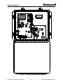
Figure 1-1: Model SGC-60 Master Controller
SG-60 High Intensity Strobe System
1-2
Manual EPM-00000019 Rev A
Airport Systems
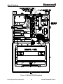
Figure 1-2: Model SGF-60 Flashhead
SG-60 High Intensity Strobe System
1-3
Manual EPM-00000019 Rev A
Airport Systems
1.3
Safety Precautions
The following general safety precautions must be observed during all phases of operation,
service, and repair of this equipment. Failure to comply with these precautions or with
specific warnings elsewhere in this manual violates safety standards of design,
manufacture, and intended use of this equipment. Honeywell assumes no liability for the
customer’s failure to comply with these requirements, as listed below.
1. Any interruption of the protective grounding conductor (inside or
outside the instrument) or disconnecting the protective earth ground
terminal is likely to make this equipment dangerous. Intentional
interruption is prohibited.
2. Whenever it is likely that the ground protection has been impaired, the
equipment must be made inoperative by removing AC line power, and
then shall be secured against any unintended operation.
3. Ensure that only fuses with the required rated current and of the
specified type (normal blow, time delay, etc.) are used for replacement.
The use of repaired fuses and the short-circuiting of fuseholders must
be avoided.
4. Electrical energy available at many points may result in personal injury
or death if touched. Any adjustment, maintenance, and repair of the
opened equipment while power is applied shall be avoided as much as
possible, however some maintenance described in this manual is
performed with power supplied to the equipment while protective
covers are removed. When repair with power applied is unavoidable,
maintenance shall be carried out only by a skilled person who is aware
of the hazard involved. Do not attempt internal service or adjustment
unless another person, capable of rendering first aid and resuscitation,
is present.
5. Do not install substitute parts or perform any unauthorized modification
to the equipment.
6. Capacitors inside the equipment may still be charged after the
equipment has been disconnected from its power source, even though
the equipment was designed to drain charge from the capacitors when
power is removed. Do not put hands or tools in the Flashhead until
the High Voltage Indicator neon lamp DS1 on the High Voltage &
Trigger board is extinguished. (Refer to Figure 1-2, Page 1-3, for
the location of High Voltage Indicator DS1 - do not confuse the High
Voltage Indicator DS1, with the PWR ON lamp DS1.) Note that it is
possible for the High Voltage Indicator DS1 to be lit even when the
PWR ON lamp DS1 is off. If this happens, the energy storage
capacitors C1 - C3 must be discharged before performing
maintenance.
SG-60 High Intensity Strobe System
1-4
Manual EPM-00000019 Rev A
Airport Systems
WARNING!
This system uses lethal voltages in the Flashhead. Unless absolutely
necessary, do not attempt to service or adjust the equipment with AC
line power applied.
Safety interlock switches are provided in the Flashhead enclosure to
interrupt main AC power to the power supply. These interlock switches
are activated when the Flashhead door is opened in a conventional
manner. No interlock is provided when other means of access are used.
Never tamper with (remove, short circuit) the interlocks in any way.
AC LINE VOLTAGE IS STILL PRESENT WHEN INTERLOCKS ARE
ACTIVATED. DISCONNECT POWER AT THE MAIN AC CIRCUIT
BREAKERS BEFORE INSPECTING OR SERVICING, UNLESS
ABSOLUTELY NECESSARY TO PERFORM MAINTENANCE WITH
POWER ON.
WARNING!
Flashtubes in this lighting system produce brilliant flashes of light
containing some ultraviolet radiation that can cause temporary or
permanent eye damage.
DO NOT LOOK DIRECTLY AT THE FLASHHEAD WHILE IT IS IN
OPERATION.
SG-60 High Intensity Strobe System
1-5
Manual EPM-00000019 Rev A
Airport Systems
1.4
Specifications
Light Output:
Day Intensity..............................................270,000 ±25% effective candelas, single flash
Twilight Intensity..........................................20,000 ±25% effective candelas, single flash
Night Intensity......................................... 2,000 ±25% effective candelas, burst of flashes
Beam Pattern...............................................................120º horizontally, 3 º min. vertically
max. intensity of 3% of peak at -10º
Flash Rate: Day......................................................................... 40 fpm - single white flash
Twilight.................................................................. 40 fpm - single white flash
Night................................................................40 fpm - white burst of flashes
Master/Slave Operation ........ Up to 24 slave SGF-60 Flashheads may share a common
sync and photocell circuit from one SGC-60 Master Controller.
Electrical Input:
Master Controller...................... 50 Watts. 120, 208, 240, 277, 380, 480 VAC. 50, 60Hz
Flashhead............................... 500 Watts. 120, 208, 240, 277, 380, 480 VAC. 50, 60Hz
Requires specific voltage selector block and manual
change to transformer wiring for different AC voltages.
Mechanical Properties:
Flashhead
Weight...........................................................................................82 pounds (37.2 kg)
Dimensions ............. 18.88"w (479.4mm) x 15.25"h (387.4mm) x 10.75"d (273.1mm)
Surface Area....................................................................................... 1.89 square feet
Wind Load .............................................................. 100 pounds at 150 mph (240kph)
Master Controller
Weight ……………………………………………………… ........24 pounds (10.89 kg)
Dimensions ....................................... 14"w (356mm) x 12"h (305mm) x 6"d (152mm)
Operating Environment:
Operating Temperature.............................................................................. -55ºC to +55ºC
Humidity.............................................................................................95% relative humidity
System Operating Status Indicators:
Flashhead, AC line power present ...............................................PWR ON Indicator DS1
Flashhead, high voltage present on capacitors .................... High Voltage Indicator DS1
(located on Trigger / High Voltage board)
Master Controller Indicators
Flashhead Status .......................................................... LEDs DS1 - DS24, red/green
Day Mode ..............................................................................................LED DS25 red
Twilight Mode ........................................................................................LED DS26 red
Night Mode ............................................................................................LED DS27 red
SG-60 High Intensity Strobe System
1-6
Manual EPM-00000019 Rev A
Airport Systems
Flashhead Fail......................................... Relay K1 de-energized and LED DS29 Off
Photocell Fail .......................................... Relay K2 de-energized and LED DS30 Off
Power Fail................................................ Relay K3 de-energized and LED DS31 Off
Night Mode Operation ............................. Relay K4 de-energized and LED DS32 Off
White Night Backup (Dual Systems) ........... Relay K5 energized and LED DS33 On
SG-60 High Intensity Strobe System
1-7
Manual EPM-00000019 Rev A
Airport Systems
SECTION 2. INSTALLATION & POWER UP
WARNING!
Modifications to the Power Supply are required for certain applications.
Remove input power at circuit breakers and discharge capacitors with
an approved grounding rod before attempting any necessary
modifications.
2.1
Unpacking
Carefully unpack each item and remove any internal packing material from the master
controller, and the flashhead/power supply. Carefully check the supplied materials with
the High Intensity Lighting System bill of materials. There are many small items that
should be supplied inside clear plastic bags, verify each of these bags contain the
proper amount of parts per the bill of materials. Report any shortages of materials
immediately to the Honeywell Technical Support.
Examine each item for obvious physical damage. Report any claims to the carrier
immediately. Pertinent data such as installation drawings, schematics, interconnection
drawings, and operation manuals are included in the Master Controller carton. The
flashtubes are packaged separately inside each Flashhead carton. Do not remove
flashtubes from their boxes until you are ready to install them.
2.2
System Configuration
Honeywell pre-configures the system to match the installation. However, there are
cases where complete installation information is not available prior to the system
leaving the factory or the installation has changed. Setting the configuration may also
be necessary when replacing individual units in the system. The following is a guide
for configuring the Master Controller and the Flashheads.
2.2.1
Master Controller Configuration
There are a number of system control switches and configuration switch blocks (DIP
switches) on the Master Controller. The configuration switch blocks may have multiple
switches. Reference to the individual switches will be made by referring to the switch
block number followed by the number of the individual switch as labeled on the switch
block. For example, SW1 (Figure 2-10, Item 1, Page 2-25) has 5 individual switches.
The third switch from the left is labeled as #3 on the switch block and will be referred to
as SW1-3.
SG-60 High Intensity Strobe System
2-1
Manual EPM-00000019 Rev A
Airport Systems
2.2.1.1
System Controls
Set Master Controller switches (Figure 1-1, Page 1-2) as follows:
POWER SWITCH -------------------------------------------------------------------------- OFF
LOCAL / REMOTE Switch ------------------------------------------------------------ LOCAL
MODE Switch ------------------------------------------------------------------------------- DAY
The Master Controller has the following control switches (Figure 1-1, Page 1-2):
•
POWER SWITCH: Toggle switch that turns input AC line power on/off in the Master
Controller. Does not affect AC power to the Flashheads. Input voltage is present at
terminal block PB1, even with the power switch turned off.
•
RESET Switch: Momentary pushbutton that resets the Master Controller. Switch
must be held for about one second to activate.
•
REMOTE / LOCAL Mode Switch: Two-position toggle switch that permits manual
(local) selection of the flash intensity level using the DAY / TWILIGHT / NIGHT
rotary switch. In normal (remote) operation, permits automatic operation controlled
by the Ambient Light Sensor photocell.
•
DAY / TWILIGHT / NIGHT Switch: Three-position rotary switch that allows manual
selection of three light intensities of the system (DAY = high, TWILIGHT =
intermediate, and NIGHT = low). The REMOTE / LOCAL Mode Switch must be in
the LOCAL position to use this switch.
2.2.1.2
Power Configuration
The input voltage selection is set at the factory prior to shipping. The user shall verify
the correct voltage as indicated by the label by Power In terminal block PB1 (Figure
1-1, Page1-2). If the voltage listed on the label does not match the voltage at the site,
contact Tech Support at (805) 581-5591.
2.2.1.3
•
Configuration Switches
SW1 – (Figure 2-10, Item 1, Page 2-25). This switch is used to set the
number of Flashheads (including antenna obstruction light (AOL)) in the
system up to 24. If the switches are set for more than 24 the system will still
monitor only 24 Flashheads. The number of lights configured equals the sum
of all the switches set to ON (positive binary). For example, to configure for
10 Flashheads, set SW1-4 (8 lights) to ON and SW1-2 (2 lights) to ON for a
total of 10 (8+2) lights.
§ SW1-1 – Set to ON (up) for 1 light
§ SW1-2 – Set to ON (up) for 2 lights
§ SW1-3 – Set to ON (up) for 4 lights
§ SW1-4 – Set to ON (up) for 8 lights
§ SW1-5 – Set to ON (up) for 16 lights
SG-60 High Intensity Strobe System
2-2
Manual EPM-00000019 Rev A
Airport Systems
•
SW2 – (Figure 2-10, Item 2, Page 2-25) This switch is used to set for
Catenary operation (suspended cable warning lights) and for Dual systems
(Red lights at night, and white strobes during the day).
§ SW2-1 – Set to ON (up) for Catenary system.
§ SW2-2 – Set to ON (up) for Dual system.
§ SW2-3 – Set to OFF (down). Reserved for future use.
•
SW3 – (Figure 2-10, Item 8, Page 2-25) This switch is used to set the
termination resistor for the communications line.
§ SW3-1 – Set to ON if the Master Controller is at the end of the
communications line. In a typical installation, the communications lines
are terminated at the Master Controller and at the top level of
Flashheads. In this case, this switch should be set ON.
2.2.2
Flashhead Configuration
All of the configuration for the Flashhead in done on the digital controller board.
Because of the high voltage present in the Flashhead, there are interlock switches and
fuses as follows (Figure 1-2, Page 1-3):
•
S1 POWER Interlock Switch: Three-position push/pull switch. When the
Flashhead door is opened, S1 interrupts AC line power to transformers T1 and
T2 when using 120VAC single-phase power. (When using 2-phase AC power,
S1 does not interrupt AC power to transformers T1 and T2.) When the
Flashhead door is opened, the PWR ON lamp DS1 to turn off. Also interrupts
power to relay K1, causing the high voltage to be shut off and the energy storage
capacitors to discharge. When door is open and S1 is pulled out manually, the
interlock is defeated, which allows the Flashhead to operate under power.
•
S2 MODE Interlock Switch: Three-position push/pull switch. When the
Flashhead door is opened, transfers flash intensity mode select from remote
control (by SGC-60 Master Controller) to local control using switch S3. When
door is open and S2 is pulled out manually, the interlock is defeated, which
allows the Flashhead to operate under remote mode control.
•
S3 MODE TEST Switch: Three-position rotary switch allows local flash intensity
mode selection (Day, Twilight or Night) for the individual Flashhead, while not
affecting the operation of any other Flashhead in the system.
•
F1 Main Power Line Fuse: Provides protection for AC power to transformer T1.
Value varies with input AC line voltage. Refer to Section 7.0 for the correct fuse
values. Honeywell provides the correct fuse for the supplied power configuration.
•
F2 Logic Power Line Fuse: Provides protection for the AC power to the logic
transformer T2. Value varies with input line voltage. Refer to Section 7.0 for the
correct fuse values. Honeywell provides the correct fuse for the supplied power
configuration.
SG-60 High Intensity Strobe System
2-3
Manual EPM-00000019 Rev A
Airport Systems
2.2.2.1
Power Configuration
The Flashhead(s) are factory set for the correct AC input line voltage. However, the
user shall verify that the AC line voltage selector block (located on the transformer
board on top of transformer T1, Figure 1-2, Page 1-3) is labeled with the correct AC
line voltage used at the site. For example, voltage selector block part number 77-3319
is labeled for 120VAC. If the voltage selector block is not labeled for the correct AC
line voltage used at the site, the correct voltage selector block must be obtained from
Honeywell, and the AC input wiring to transformer T2 must also be verified and
corrected if necessary according to Figure 3-2, Page 3-12.
2.2.2.2
•
Configuration Switches
SW1 – (Figure 2-11, Item 2, Page 2-26) This switch is used to reset the
processor
§ Press and hold – resets the processor and tests the automatic power
reset circuit. Press and hold SW1 until the 5v power indicator (DS1,
Figure 2-11, Item 1, Page 2-26) turns OFF momentarily then release.
•
SW2 – (Figure 2-11, Item 4, Page 2-26) This switch is used to set special
operation options. Set all four switches to OFF unless your system meets
one of the two conditions below:
CONDITION 1: You have a Catenary System
§ SW2-1 – Set ON for all Flashheads on top level of a Catenary installation.
§ SW2-2 – Set ON for all Flashheads on bottom level of Catenary
installation.
§ SW2 -1 & -2 – Set both to ON for all Flashheads on middle level of a
Catenary installation.
CONDITION 2: You have Dual (Red/White) system with an older-model
Master Controller.
§ SW2-3 – Set to ON. This is provided for backward compatibility with
older installations only. For new installations this switch is always
OFF. For older white-only installations this switch is also OFF.
To determine if an existing installation has an older Master Controller,
refer to the new Master Controller in Figure 2-10, Page 2-25. Older
Master Controllers do not have terminals TB5-TB9, or an EXT RED switch
SW2-2 (Item 2 in the figure).
Note: Switch SW2-4 is a spare reserved for future use.
SG-60 High Intensity Strobe System
2-4
Manual EPM-00000019 Rev A
Airport Systems
•
SW3 – (Figure 2-11, Item 3, Page 2-26) Used to specify the ID number for
the Flashhead. Each Flashhead must be set with a unique ID number as
indicated on the installation drawings. There is a diagram next to the switch
showing the values for the switch. The ID number is the total of the values of
the switches set to OFF (negative binary). For example, to set ID #10, set
SW3-2 (value 2) OFF (down) and SW3-4 (value 8) OFF (down) for a total of
10 (2+8).
§ SW3-1 – Set to OFF (down) for value 1
§ SW3-2 – Set to OFF (down) for value 2
§ SW3-3 – Set to OFF (down) for value 4
§ SW3-4 – Set to OFF (down) for value 8
§ SW3-5 – Set to OFF (down) for value 16
•
SW4 – (Figure 2-11, Item 5, Page 2-26) This is used for the terminating
resistor on the communications line.
§ SW4-1 – Set to ON (up) for terminating resistor. This should be set ON
only for the Flashhead where the communication lines are terminated. In
a typical installation, the communications lines are terminated at the
Master Controller and the upper most Flashhead. In systems with an
AOL, the AOL is typically the upper most Flashhead. In systems without
an AOL, any one but only one of the Flashheads at the top level can be
set to ON. For all others, set to OFF. If the system is being installed in
stages as the tower is erected, SW4-1 should be set ON for one of the
flashheads at the highest installed level. As additional flashheads are
added at higher levels, adjust the configuration by setting SW4-1 to OFF
in the previous flashhead and set SW4-1 to ON for one of the flashheads
at the highest installed level.
2.2.2.3
Flashtube Installation
The Flashheads are shipped from the factory without the flashtubes installed to prevent
damage during shipping. Install the flashtubes per the following procedure:
1.
If Flashhead is already wired to AC power: Shut off the power to the system
by opening the main AC power circuit breakers.
2.
Release the Flashhead cover latches.
3.
Swing the cover open, exercising caution not to damage the glass face or the
gasket.
4.
Unpack the flashtube. Do not touch the glass envelope - contamination from
a fingerprint will degrade the reliability of the flashtube.
5.
Holding the flashtube by its metal ends, center it in the reflector assembly
and snap it into place. Make sure the red mark on the flashtube matches the
red mark on the socket assembly.
6.
Attach the fast-on connector at each end of the flashtube to each socket
assembly. Make sure wires are not twisted - the metal to glass bond is fragile.
SG-60 High Intensity Strobe System
2-5
Manual EPM-00000019 Rev A
Airport Systems
7.
Refer to Figure 2-1 below. Dress the electrode wires away from the sides of
the reflector.
8.
Close and fasten the Flashhead cover.
Figure 2-1: Flashtube Installation
2.3
2.3.1
Installation
SGC-60 Master Controller
The Master Controller is connected to Flashheads via the data communications cable
provided by Honeywell. The length of this cable (up to 2500 feet) determines how far
the Master Controller can be mounted from the Flashheads.
A detailed drawing for mounting the Master Controller is shown in Figure 2-2, Page 2-9
2.3.2
SGF-60 Flashhead
Normally the Flashheads are mounted at the uppermost point and additional
referenced elevations on the structure. The Flashhead is connected to its Master
Controller via the data communications cable provided by Honeywell. The length of
this cable (up to 2500 feet) determines how far any Flashhead can be mounted from
the Master Controller.
Honeywell labels all the Flashheads with numbers ranging from 1 to 24 depending on
the number of required lights for the structure. Typically, the upper most level of lights
will contain the lights with numbers 1 through 3 or 4. If the structure has an
appurtenance of greater that 40 feet, an AOL (Antenna Obstruction Light) is required
and it will have a Flashhead Number of 1. The High Intensity Flashheads will start with
Flashhead Number 2. The flashheads should continue down the tower from the top
sequentially ending with the highest number at the bottom level.
The vent hole on the bottom surface of the power supply is covered with a solid plug
prior to shipping. Optional screened plugs are furnished separately.
SG-60 High Intensity Strobe System
2-6
Manual EPM-00000019 Rev A
Airport Systems
Typically, the Flashhead is mounted to a bracket, which is then attached to the
structure. Honeywell can supply brackets for most types of installations.
A detailed drawing for mounting the Flashhead is shown in Figure 2-3, Page 2-10.
2.3.2.1
Setting the Flashhead Elevation
Flashheads must be mounted at the proper vertical angle to assure proper light output.
Depending on the elevation of the light level, the Flashhead may need to be adjusted to
reduce the amount of ground scatter. Please refer to the table below for proper
elevation for the lights.
1. Slightly loosen the angle lock bolts, which are at the bottom of the mounting
arms (see Figure 2-3, Page 2-10). The bolt heads and nuts fit 7/16" wrenches or
nut drivers (tightening will require a pair of tools).
2. Adjust the Flashhead enclosure until the bubble indicator on top of the enclosure
reads level.
3. Take note of the position of the bolt with respect to the silk-screened markings
on the angle indicator. This position is the zero degree position. The markings
are screened at intervals of one degree.
4. Adjust the Flashhead enclosure to aim the beam upward until the bolt head has
shifted by the number of degrees indicated in the table below.
5. Securely tighten both angle lock bolts.
Light Unit Elevation Above the Horizontal
2.3.3
Height of Light Unit Above
Ground Level
Degrees of Elevation above
Horizontal
More than 500 feet
0°
401 feet to 500 feet
1°
301 feet to 400 feet
2°
Less than 300 feet
3°
Ambient Light Sensor (Photocell)
The Ambient Light Sensor, when supplied with the system, shall be mounted upright,
away from artificial light (e.g. floodlights), and in a location that will enable the sensor
window to have an unobstructed view of the polar sky (pointed north in the northern
hemisphere, not pointed toward the sun). The photocell housing wire entry is tapped to
allow mounting to 1/2" threaded pipe. Conduit and related hardware will be
supplied by the customer. A 21-foot 3-conductor cable is attached to the photocell
for remote installation.
SG-60 High Intensity Strobe System
2-7
Manual EPM-00000019 Rev A
Airport Systems
2.3.4
Cables and Junction Boxes
The cables shall be properly supported and terminated in the junction boxes per the
detailed description provided in section 2.4, page 2-11 of this document. Additional
information regarding cables and junction box installation can be found on the drawing set
for the lighting system. Particular attention should be paid to assure that the data cable
shields are isolated from the junction box housings.
SG-60 High Intensity Strobe System
2-8
Manual EPM-00000019 Rev A
Airport Systems
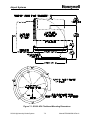
Figure 2-2: Master Controller Mounting Dimensions
SG-60 High Intensity Strobe System
2-9
Manual EPM-00000019 Rev A
Airport Systems
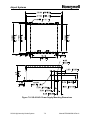
Figure 2-3: Flashhead Outline and Mounting Dimensions
SG-60 High Intensity Strobe System
2-10
Manual EPM-00000019 Rev A
Airport Systems
2.4
Installation Wiring
Follow the procedure below to perform the installation wiring. Note that the wiring of the
Alarm Relay outputs is customer and site specific and is therefore not specified in this
manual.
Figure 2-5: Typical Wiring Installation
SG-60 High Intensity Strobe System
2-11
Manual EPM-00000019 Rev A
Airport Systems
2.4.1
Master Controller to Photocell Wiring
The photocell is supplied with a length of wire attached. If a longer wire is needed, this
should be accomplished using a junction box. Make the interconnect between the
external Photocell and the Master Controller TB2 per Figure 2-5, Page 2-11, as
follows.
Black wire
White wire
Red wire
2.4.2
Photocell ------------------------ to -----------Master Controller TB2-B
Photocell ------------------------ to ---------- Master Controller TB2-W
Photocell ------------------------ to -----------Master Controller TB2-R
Master Controller Data/Communications Wiring
Typically, the data/communications wiring is done with Honeywell P/N WC000002, a
shielded, twisted-pair cable. It has one pair of conductors, and a drain wire for making
shield connections. This cable is routed up the structure in the same conduit as the
Flashhead power wiring. Connect the data cable wires to Master Controller TB5
according to Figure 2-5, Page 2-11, and as follows:
White or Clear wire (Data signal "A") ------- to ---------------- Master Controller TB5-A
Blue wire (Data signal "B") --------------------- to ----------------Master Controller TB5-B
Shield drain wire (Data shield) ----------- to --------------Master Controller TB5-S
(TB5-S is position 4)
The Data Shield (TB5-S) is grounded by the factory-installed wire that connects
the E1 ground lug on the Master Controller circuit board to PB1-G.
If you need to connect a Flashhead directly to the Master Controller using the data
cable integrated into Flashhead Cable WC000002, use the following connections.
White or Clear wire -----Master Controller TB5-A -----------to ---- Flashhead TB1-4
Blue wire-------------------Master Controller TB5-B -----------to ---- Flashhead TB1-5
Inner Shield ---------------Master Controller TB5-S (4) -------to ---- Flashhead TB1-6
Outer Shield --------------------------------------------------------- not connected at either end
2.4.3
Master Controller Power Wiring
Make the connections for incoming AC line power to Master Controller PB1 per Figure
2-5, Page 2-11 as follows. These wires (or cable) are not supplied by Honeywell. A
separate circuit breaker is recommended for the Master Controller. The Master
Controller may, if desired, use a different AC line voltage than the Flashheads.
The wire colors below are typical for single-phase power. Be sure to check your own
installation colors.
Black wire (Phase or hi) ----------------------------- to ----------- Master Controller PB1-L
White wire (Phase or neutral) ---------------------- to -------- Master Controller PB1-L/N
Green wire (Equipment ground) ---------------- to--------- Master Controller PB1-G
SG-60 High Intensity Strobe System
2-12
Manual EPM-00000019 Rev A
Airport Systems
2.4.4
Master Controller Wiring For Dual Systems
If your installation is a Dual (Red/White) system, you must make additional connections
to coordinate between the High Intensity Strobe System and the Red Light System.
See the sections below for wiring details. For configuration switch settings for a Dual
system, see 2.2.1.3 on Page 2-2.
2.4.4.1
Controlling the Red Light System
The Master Controller uses Relay K4 to control the Red Light System. The Relay K4
contacts should be wired to the Red Light System in such a way that when K4 is
energized, the Red Lights turn off, and when K4 is de-energized, the Red Lights turn
on.
Typically this is done by disconnecting the Red Light System photocell, and wiring
those photocell inputs to the Relay K4 contact. The contacts are rated for up to 5A,
and up to either 30VDC or 250VAC.
If your red light system has a Honeywell 9LCA-Series Red Light Controller, the 9LCA
photocell is not used. Instead of connecting the 9LCA photocell to 9LCA terminal TB3,
make the following connections:
Master Controller TB3-C4--------------- to -------- 9LCA Red Light Controller TB3-B
Master Controller TB5-NO4 ------------ to ----------9LCA Red Light ControllerTB3-R
Configure the 9LCA Red Light Controller to use Automatic mode control. Other Red
Light Systems may require different connections. Refer to the Tower Kit drawing (if
Honeywell provided both systems as a kit), refer to the Red Light System's manual, or
contact Honeywell for assistance.
2.4.4.2
Responding to Top Red Beacon Failures
When a top-level red beacon fails at night, a Dual system must switch from red to white
lights. The Master Controller will switch to the white strobes at night if it detects an
open circuit between TB6-1 and TB6-2 ("EXT RED").
Install external wiring must in a single electrical loop from TB6-1 to TB6-2 in such a way
that the loop is closed when all the top-level red beacons are operating correctly, and
the loop is opened (broken) when any top-level red beacon fails.
The External Red Ready indicator (LED DS36 -- Item 10 in Figure 2-10, Page 1-2)
turns on to indicate a closed loop (Red Lights OK), and turn off to indicate an open loop
(Red Light Failure).
SG-60 High Intensity Strobe System
2-13
Manual EPM-00000019 Rev A
Airport Systems
If your red light system has a Honeywell 9LCA Series Red Light Controller, locate the
Alarm terminals and Flasher Bypass terminals corresponding to the top beacon, and
make the following connections:
Master Controller TB6-1 -----------------to ----------------------9LCA Flasher Bypass C1
9LCA Flasher Bypass NC1 -------------to ---------------------------- 9LCA Alarm Card C1
Master Controller TB6-2 -----------------to --------------------------9LCA Alarm Card NC1
Note: Usually the top beacon terminals are found on the top/left Flasher Bypass Card
(TB4), and the left channel of the top Alarm Card (TB3).
Other Red Light Systems may require different connections. Refer the to Tower Kit
drawing (if both systems were provided as a kit by Honeywell), the Red Light System's
manual, or contact Honeywell for assistance.
2.4.5
Flashhead Wiring
Incoming AC power and data communications enter the Flashhead in a single cable,
Honeywell P/N WC000001, that combines three wires for AC power with a
twisted-pair/double-shielded data cable (See Figure 2-9, Page 2-21).
Typically,
Flashheads are supplied with a 10-20 foot length of this cable already installed.
Should you need to install or replace this cable, make the connections for incoming AC
power and data to Flashhead TB1 per Figure 2-5, Page 2-11, and Figure 2-10, Page 224, as follows.
Green wire (Equipment ground) ------------------------to----------------- Flashhead TB1-1
White wire (Phase or neutral) ---------------------------to----------------- Flashhead TB1-2
Black wire (Phase or hi) ----------------------------------to----------------- Flashhead TB1-3
Data Cable
White or Clear wire (Data signal "A") ------------to----------------- Flashhead TB1-4
Blue wire (Data signal "B") --------------------------to----------------- Flashhead TB1-5
Inner shield (Data shield)----------------------------to----------------- Flashhead TB1-6
Outer shield -------------------------------------------------------- trim short; not connected
2.4.6
Conduit and Tower Wiring Detail
This section details a standard practice of installing conduit and the related tower
lighting wires for the system. Please use this guide to help install the wires into the
conduit system. The wires and cables for the SG-60 High Intensity system need to be
run properly to insure that the system will work properly. Wire insulation that is
damaged will lead to a system that will not function properly and may void the warranty.
Insure that the following procedure is followed. Pay close attention to all bold text.
SG-60 High Intensity Strobe System
2-14
Manual EPM-00000019 Rev A
Airport Systems
Figure 2-5: Flex Conduit Typical Installation Layout
2.4.6.1
Procedures for installation of conduit and tower wiring
1. All conduit, junction boxes, mounting hardware, fixtures, etc. provided for
installation of the electrical system (i.e. lighting or equipment power distribution)
should be inventoried and checked against the appropriate bills of materials.
(a)
Conduit and junction box components provided for electrical
systems should be checked against appropriate bills of materials to
ensure all are present and of proper size.
(b)
Numbers of wires to be carried by each conduit run should be
checked against National Electrical Code. Honeywell sizes the
conduit run for a 40% fill of the conduit by the NEC.
2. Use pipe compound or equivalent for all threaded connections in the conduit
run. This will prevent water from entering the conduit system and make an
electrical connection between the conduit and ground.
3. All custom cut pieces of conduit must be de-burred after they are threaded to
remove sharp edges that may cut wiring insulation. Honeywell supplies conduit
in 10-foot lengths, therefore cutting and threading of the conduit may be
necessary.
4. Insure that “chase nipples” or bushings are properly installed in all junction box
ports to protect the wiring insulation from pipe threads and other sharp edges in
SG-60 High Intensity Strobe System
2-15
Manual EPM-00000019 Rev A
Airport Systems
the junction box ports. Do not begin to run wire through a junction box port
before a chase nipple or grommet is in place.
5. Before running the wire into a box insure the wire insulation will be
protected from any sharp edges on the junction boxes. Pieces of carpet,
wide copper braid, etc. can be fastened in place over sharp edges to protect
wire insulation.
6. Precut and bundle method of wire installation:
(a)
Cut all conductors to length for their respective run with adequate
excess to allow for strain relief and additional slack for
connections.
(b)
Ensure that there is plenty of wire pulling lubricant on site before
beginning to pull wiring. Use plenty of lubricant as the wire is
being run through the conduit.
(c)
The wiring bundle should be hoisted above the junction box at the
top of the run into which it is to be inserted then lowered down into
the conduit. There should be someone at the top junction box
of the run to insure the wiring does not get scuffed or cut on
junction box edges and to apply lubricant to the wiring as it
enters the conduit.
(d)
If the conduit and wire will be installed on the ground, use the
same methods described here.
Insure proper amount of
lubricant is available and that the wire is shielded from any rough
edges on the conduit or ground that might damage the wire/cable
insulation.
(e)
Adequate slack should be pulled back up into the uppermost
junction box to effect strain relief and to make proper wiring
connections. Once wiring bundle is supported by the strain relief
mechanism, make all wiring connections in the junction box.
i. To make proper connections the wiring entering the box from
above and the wiring above, the strain relief mechanism at the
bottom of the box must be long enough. The wires at the top of
the box should be formed into a “J” shape and the last 1/2-inch
of insulation should be stripped off the conductor. The wires
from the bottom of the box supported by the strain relief
mechanism should be run up to a point just short of the top of
the junction box and cut off. The last 1/2-inch of insulation
should then be stripped from those. Wire connections should
be made with proper sized Scotch® Twist wire nuts or split bolt
connectors.
ii. Once a wire nut is installed, hold the wire nut and tug on all
wires firmly to ensure the connection of all conductors is tight.
iii. Finish each connection with at least 6 wraps of Scotch 33+ tape
or equivalent for proper moisture protection.
iv. When a proper connection is complete, the wire nut should be
positioned upside-down (wire nut opening pointing downward)
SG-60 High Intensity Strobe System
2-16
Manual EPM-00000019 Rev A
Airport Systems
(f)
(g)
and the connection should be at the top end of the junction box.
Wiring from ports in the sides of junction boxes should also be
made such that the wire nuts are at the top of the junction box
with the wire nut openings pointing downward, (see Figure 2-6,
Page 2-19) for proper moisture protection.
Move down to the next intermediate (strain relief) junction box and
pull enough of the wiring into the box to provide for the proper
installation of the strain relief mechanism.
Move down to the next intermediate junction box and repeat the
above procedure until the entire tower is wired.
SG-60 High Intensity Strobe System
2-17
Manual EPM-00000019 Rev A
Airport Systems
2.4.7
Junction Box Details
This section will detail the proper wire interconnection details for the input voltage and
data cable to the flashhead pigtail cable. These connections are very important to the
proper operation of the lighting system. The flashhead pigtail contains all the wires
required for proper interconnection between the conduit wiring and flashhead.
Additional reference materials can be found on the High Intensity Lighting system
drawing set. Please reference the below information and drawings for a proper
installation. Mis-wiring of these wires will not allow the flashheads to operate properly.
Please call the Honeywell Technical Support if you have any questions regarding the
installation of these connections. Systems that are improperly wired may void the
warranty.
2.4.7.1
Flex Conduit Installation
On each of the high intensity flashheads, a pigtail is attached at the factory for
installation to the junction box. This pigtail may not be long enough for proper routing
along the horizontal and vertical struts on the tower. The high intensity lighting system
will have a 100-foot spool of pigtail cable, Honeywell P/N WC000001, for installer to
use for those flashheads that do not have a long enough pigtail. If this spool of cable
will not accommodate all the flashheads, extra cable can be ordered from Honeywell.
The ¾” flex conduit will be used for shielding of possible RF Interference generated by
some broadcast and radio towers. The conduit will be positioned over the flashhead
pigtail and connected at the junction box and flashhead enclosure by watertight
connector designed for the ¾” flex conduit. The installation will consist of the following
materials:
¾” Flex Conduit – Honeywell part number CL000002
¾” Sealing Ring – P/N *77-1085
¾” Bushing Insulator – P/N *77-1087
¾” Flex Conduit Fitting – P/N CD000003
Consists of: Gland nut, body, edge cone, nylon seal ring, and ¾” locknut
Please reference Figure 2-7, Page 2-20 for proper installation of this conduit.
SG-60 High Intensity Strobe System
2-18
Manual EPM-00000019 Rev A
Airport Systems
Figure 2-6: Junction Box Wiring Details
SG-60 High Intensity Strobe System
2-19
Manual EPM-00000019 Rev A
Airport Systems
Figure 2-7: Flex Conduit Installation Detail
SG-60 High Intensity Strobe System
2-20
Manual EPM-00000019 Rev A
Airport Systems
The flex conduit will need to be properly mounted to the horizontal and vertical struts by
way of the supplied 20-inch cable ties. These cable ties should be placed at a
minimum of 3 feet apart for proper bonding to the tower structure. The distance
between the cable ties may need to be reduced if the installer sees that the 3-foot
distance will not allow for proper bonding and securing to the tower.
Figure 2-5, Page 2-15 depicts a standard installation layout for the Flashhead pigtails
and flex conduit.
2.4.7.2
Splicing Details for WC000001 Cable
The installation of the data/communication cable is the most important part of the High
Intensity Lighting system installation. Without a sound connection for the data cable,
the entire system will not work properly. Insure that the following steps are followed to
insure a proper installation and connection.
NOTE: Splicing of the cables at any other location besides the light level is not
recommended. The intermediate junction boxes between the light levels should be
used as pull boxes and for strain relief only, with no splices.
The WC000001 cable is a multi-conductor cable that is used for the interconnection of
the flashhead to the junction box. The WC000001 cable consists of the following
wires/cable:
Figure 2-9: WC000001 Cable Overview
Item 1 (A, B, S) is the data/communication cable that is used to transmit all the data
from the master controller, SGC-60, to the flashhead, SGF-60. Without a proper
connection, the lighting system will flash erratically, or default to Day mode.
Items 2, 3, and 4 are used for the power input from the junction box to the flashhead.
Item 5 is the Drain Wire for the outer cable shield.
SG-60 High Intensity Strobe System
2-21
Manual EPM-00000019 Rev A
Airport Systems
Item 6 is a shield drain wire that will not be used for interconnection. This wire should
be cut off flush from the cable when the outer jacket is stripped back for interconnection
of the system.
The following section is a guideline to a proper installation of the WC000001 cable.
Please follow this guideline to ensure a proper installation and interconnection in the
junction box.
1.
Strip back at least 16” of the outer jacket of the WC000001 cable. Make
sure that during this removal, the other wires are not damaged. If the
insulation is damaged on one of the other wires, a potential of lighting
problems can occur shortly after the system is connected.
2.
Remove all the aluminum foils and braids from the exposed conductors.
These will not be used for interconnection.
3.
Cut off Item #6, bare shield wire, that protrudes from the cable. This wire
will not be used for interconnection.
4.
Connect Item #5, bare shield wire, and Item #4, #12-AWG Green wire,
from all the cables to the ground lug inside the junction box. This ground
lug can be found on the back plane of the junction box or at an internal
locknut that has a ground screw attached. No other wires will be
connected to ground.
5.
Connect Item #1S, data/communication inner shield drain wire, to the
other data shield drain wires from the additional data cables. Trim back
the associated shield neatly. Make sure that this drain wire and the shield
cannot contact the walls of the junction box or other wires. Do not
connect inner shield to outer shield. Extra taping may be required for
proper isolation. The inner shield should only have a connection to
ground inside the SGC-60 controller.
On a typical installation, there will be a total of 5 wires that will be
connected together. One from the lower junction box level, three from the
flashhead cables on that level, and one for the cable going to the next
level.
6.
Connect Item #1A to corresponding wires in other four cables as stated
above in step 5.
7.
Connect Item #1B to corresponding wires in other four cables as stated
above in step 5.
8.
Connect the #12-AWG Black and #12-AWG White wires as required by
the installation drawing set supplied with the lighting system. If the
system has a 3-phase input, ensure proper connection between the
3-phase wires (typically brown, orange, and yellow) and the black and
white wires from the flashhead. Proper load balancing is required on the
three-phase input to operate efficiently (distribute the flashheads as
evenly as possible across the phases).
SG-60 High Intensity Strobe System
2-22
Manual EPM-00000019 Rev A
Airport Systems
9.
The power wires should be spliced together using split bolt connectors.
The data wires should be spliced together using Scotch® Twist Lock
connectors. After splicing, ensure all wires are secure by pulling on each
wire. Wrap each connection with at least 6 wraps of Scotch 33+ tape or
equivalent for moisture protection. All connection ends should be located
in the upper corners of the junction box with all closed end of the
connector pointing up. See Figure 2-6, Page 2-19 for reference.
Note: The Master Controller can operate from a different AC voltage than the
Flashheads if desired.
SG-60 High Intensity Strobe System
2-23
Manual EPM-00000019 Rev A
Airport Systems
** It is extremely important to connect all
Data cable inner shields together, but isolate
them from all other shields and grounds **
Figure 2-10: Flashhead Cable
SG-60 High Intensity Strobe System
2-24
Manual EPM-00000019 Rev A
Airport Systems
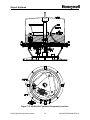
Figure 2-10: Master Controller Circuit Board
SG-60 High Intensity Strobe System
2-25
Manual EPM-00000019 Rev A
Airport Systems
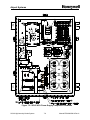
Figure 2-11: Flashhead Digital Control Board
SG-60 High Intensity Strobe System
2-26
Manual EPM-00000019 Rev A
Airport Systems
2.5
Final Installation Check
Before applying power to the equipment, perform the procedures in Sections 2.5.1 2.5.4. If any test does not pass, please consult SECTION 4. TROUBLESHOOTING in
this manual or call Honeywell Technical Support at (805) 581-5591.
2.5.1
Preliminary
1.
Verify that all AC input power circuit breakers are turned off.
2.
Check that all printed circuit boards are properly seated in their sockets, and
retaining brackets are securely fastened..
3.
Check that any user-installed wiring does not interfere with relay operation
when covers are closed.
4.
Check that all Flashheads are mounted are mounted at the correct
elevation per Section 2.3.2.1, Page 2-7. Check that all Flashhead covers
are shut properly for a weather-tight seal with all latches closed.
5.
Set Master Controller switches as follows:
POWER SWITCH ----------------------------------------------------------------- OFF
LOCAL / REMOTE Switch --------------------------------------------------- LOCAL
MODE Switch ----------------------------------------------------------------------- DAY
2.5.2
Verify Correct Wiring in Master Controller
Verify correct wiring of the Master Controller as specified in section 2.4 page 2-11.
2.5.3
Verifying Photocell Wiring
Verify correct wiring of the photocell as specified in section 2.4.3 page 2-12.
2.5.4
Verify Proper Tower Wiring for Data/Control Cable
This test assumes a typical tower configuration with the data cable terminating at the
Master Controller.
1.
Unplug Data Cable connector TB5 from PCB1 in Master Controller.
2.
Verify 120-140 ohms resistance between TB5-A and TB5-B on the Data
Cable. (This checks that a single 100-ohm data line termination resistor is
in the circuit. Resistance of 70 ohms or less indicates that more than one
Flashhead has the terminating resistor switch set to on. See SW4 page
2-5.
3.
Verify open circuit by measuring resistance between TB5-S on the Data
Cable and panel ground.
4.
Verify open circuit between TB5-A on the Data Cable and panel ground.
5.
Verify open circuit between TB5-B on the Data Cable and panel ground.
SG-60 High Intensity Strobe System
2-27
Manual EPM-00000019 Rev A
Airport Systems
6.
Verify open circuit between TB5-S and TB5-A (both on Data Cable)
7.
Verify open circuit between TB5-S and TB5-B (both on Data Cable).
8.
In one of the top-most Flashheads, install a jumper (or alligator clip)
between TB1-5 and TB1-6.
9.
Verify short circuit between (<20 ohms) TB5-S and TB5-B (both on Data
Cable).
10.
Remove the jumper between TB1-5 and TB1-6.
11.
Verify open circuit between TB5-S and TB5-B (both on Data Cable)
12.
On the Master Controller card, measure between TB5-A and TB5-B and
verify 120 ohms +/- 10% resistance. If not, check for proper configuration.
See SW4 on page 2-5.
13.
Plug Data Cable Connector TB5 back into PCB1.
14.
Verify short circuit between TB5-S screw terminal and panel ground.
2.6
Power Up and System Tests
During the power up of the system, there are indicator lights which will be checked to
verify correct operation and installation.
The following is a description of all the
indicators in the Master Controller and the Flashheads. The indicators in the
Flashhead need not be checked unless problems are encountered during the normal
power up tests.
2.6.1
Master Controller Status Indicators
•
Photo Mode Indicators (Figure 2-10, Item 3, Page 2-25)
§ DS25 – Red indicates active mode is Day
§ DS26 – Red indicates active mode is Twilight
§ DS27 – Red indicates active mode is Night
§ DS28 – Green indicates photocell is OK, Red indicates photocell is bad
•
Individual Flashhead Status (Figure 2-10, Item 4, Page 2-25)
§ DS1-24 – Green indicates Flashhead is good, OFF indicates Flashhead
has not been selected for monitoring, Red indicates Flashhead is bad.
•
Miscellaneous Indicators
§ DS34 – (Figure 2-10, Item 7, Page 2-25) ON indicates transmit OK
§ DS35 – (Figure 2-10, Item 9, Page 2-25) Flashing indicates sync input
read OK.
§ DS36 – (Figure 2-10, Item 10, Page 2-25) ON indicates red lights are
available, OFF indicates red lights are reporting alarm or not installed
SG-60 High Intensity Strobe System
2-28
Manual EPM-00000019 Rev A
Airport Systems
§
§
§
§
2.6.2
DS32 - 33 – (Figure 2-10, Item 5, Page 2-25) The indications on these
lights are dependent on the setting for external red light system on SW2.
If SW2-2 is set for an EXTERNAL RED system (ON), then
• DS32 – ON indicates there has been a red light system alarm
sometime during the night and the red light system is off, but will reset
the next day. OFF when in night mode and the red light system is not
in alarm
• DS33 – ON indicates in night mode, red lights are turned off and white
strobes are operating, OFF indicates NORMAL operation.
If SW2-2 is set for no EXTERNAL RED system (OFF) then
• DS32 – ON during DAY and TWILIGHT, OFF during NIGHT mode
• DS33 - Not used (lower right of board)
DS31 – (Figure 2-10, Item 5, Page 2-25) ON indicates power OK, OFF
indicates power failure
DS30 – (Figure 2-10, Item 5, Page 2-25) ON indicates photocell is
GOOD, OFF indicates photocell is BAD or not connected
DS29 – (Figure 2-10, Item 5, Page 2-25) ON indicates all Flashheads are
good, OFF indicates one or more Flashheads are bad
Flashhead Status Indicators
•
2.6.3
Miscellaneous Indicators (Figure 2-11, Item 1, Page 2-26)
§ DS1 Red
ON for 5-Volt logic power OK
§ DS2 Yellow ON for Flash Current Feedback OK
§ DS3 Green ON Steady for communications OK (receive & transmit)
OFF for no communications reception
Slow Blink (1/sec) for receiving but not being addressed to
transmit
Fast Blink (4/sec) for receiving, being addressed to transmit
but failing to transmit
System Power Up
All switches and indicators listed in this section are in the Master Controller, except for
the external system circuit breakers.
1.
Verify POWER SWITCH is turned OFF.
2.
Verify LOCAL / REMOTE switch is set to LOCAL.
3.
Verify MODE switch is set to DAY.
4.
Turn on circuit breaker to apply power to Master Controller.
5.
Turn on circuit breaker to apply power to Flashheads.
6.
Turn POWER SWITCH to ON.
SG-60 High Intensity Strobe System
2-29
Manual EPM-00000019 Rev A
Airport Systems
7.
Verify that the LED test sequence has started. The test sequence will
exercise every LED and relay (e.g. it will quickly sweep through the
Flashhead Status LEDs in red and green mode).
After the test sequence completes, the Flashhead status LEDs for the
selected number of Flashheads shall be lit red then change to green as
the Flashheads report (DS1 - DS24, Figure 2-10 Item 4, Page 2-25).
8.
After 1 minute, verify the number of Flashhead status LEDs (DS1 - DS24,
Figure 2-10 Item 4, Page 2-25) that are lit green matches the total number
of white Flashhead lights (including AOL) on the tower (if there are n
Flashheads on the tower, Flashhead status LEDs DS1 - DSn shall be lit
green). Verify that the remaining unused Flashhead status LEDs (DSn+1
- DS24) are turned off.
Once all the flashheads report good (green), the relay monitor LEDs
should display as follows: DS29-DS32 GREEN, DS33 OFF (DS29 DS33, Figure 2-10 Item 5, Page 2-25).
9.
Verify Photocell status LED DS28 (Figure 2-10, Item 3, Page 2-25) is lit
green.
10.
Verify Day Mode LED DS25 (Figure 2-10, Item 3, Page 2-25) is lit red,
and the Twilight and Night LEDs (DS26 and DS27 respectively (Figure
2-10, Item 3, Page 2-25)) are not lit.
11.
Hold down the RESET switch for approximately 1 second and verify the
LED test sequence has restarted.
12.
Wait 1 minute and measure the voltage between TB1-1 and TB1-2 to
verify the voltage is 12-18 VAC. Repeat steps 7 - 10 to assure proper
recovery after reset.
2.6.4
Verify Local Mode Operation
All switches and indicators listed in this section are in the Master Controller.
2.6.4.1
Day Mode:
1.
Verify MODE Switch is set to DAY.
2.
Verify Day mode LED DS25 (Figure 2-10 Item 3, Page 2-25) is lit red.
3.
After about 6 seconds, verify all Flashheads are flashing in sync and in
Day mode (maximum brightness).
4.
Verify that the Flashhead Status LED for each Flashhead on the tower is
lit green (including any AOL). Unused Flashhead status LEDs shall be
off. (DS1 - DS24: Figure 2-10, Item 4, Page 2-25)
5.
Verify relay status LEDs DS29-DS32 are lit green, ans DS33 is OFF.
(Figure 2-10, Item 5, Page 2-25)
SG-60 High Intensity Strobe System
2-30
Manual EPM-00000019 Rev A
Airport Systems
6.
If you have a Dual (Red/White) System, the Red Lights should be OFF.
7.
If you have a Catenary System, Verify Catenary flash timing.
2.6.4.2
(a)
All Flashhead on Middle Level should flash together.
(b)
All Flashheads on Top Level should flash together
(c)
All Flashheads on Bottom Level should flash together.
(d)
Middle Level Flashheads should flash first.
(e)
Top Level Flashheads should flash second (1/13 second later)
(f)
Bottom Level Flashheads should flash third (2/13 second after
Top)
(g)
Sequence should repeat every 1 second. (Time between Bottom
and Middle flash is 10/13 seconds).
Twilight Mode:
1.
Set MODE Switch to TWILIGHT.
2.
Verify Day and Night mode LEDs (DS25 and DS27 respectively Figure
2-10, Item 3, Page 2-25) are unlit and the Twilight mode LED DS26 is lit
red.
3.
After 6 seconds, Verify all Flashheads are flashing in sync and in Twilight
mode (medium brightness).
4.
Verify that the Flashhead Status LED for each Flashhead on the tower is
lit green (including any AOL). Unused Flashhead status LEDs shall be
off. (DS1 - DS24: Figure 2-10, Item 4, Page 2-25)
5.
Verify relay status LEDs DS29 - DS32 are lit green, and DS33 is off.
(Figure 2-10, Item 5, Page 2-25)
6.
If you have a Dual (Red/White) System, the Red Lights should be OFF.
2.6.4.3
1.
Night Mode
Set MODE Switch to NIGHT.
2.
Verify Day and Twilight mode LEDs (DS25 and DS26 respectively (Figure
2-10, Item 3, Page 2-25) are unlit and Night mode LED DS27 is lit red.
3.
Verify that the Flashhead Status LED for each Flashhead on the tower is
lit green (including any AOL). Unused Flashhead status LEDs shall be
off. (DS1 - DS24: Figure 2-10, Item 4, Page 2-25)
4.
Verify relay status LEDs DS29-DS31 are lit green, and DS32 and DS33
are off. (DS29 - DS33: Figure 2-10, Item, 5, Page 2-25)
5.
If you have a White-Only System: After 6 seconds, Verify all Flashheads
are flashing in sync and in Night mode (lowest brightness, ~1/8 second
duration bursts at 40 bursts per minute).
SG-60 High Intensity Strobe System
2-31
Manual EPM-00000019 Rev A
Airport Systems
6.
7.
If you have a Dual (Red/White) System: Verify normal red night mode
operation.
(a)
Verify that all Flashheads are OFF
(b)
Verify that all Red Lights are ON and flashing properly, and the
Red Light Controller does not indicate any alarms in the top-most
Red Beacons.
(c)
Verify that LED DS36 (EXT RED READY) is lit green (See Item 10,
Figure 2-10, Page 2-25).
If you have a Dual (Red/White) System: Perform the following steps to
check white night backup operation.
(a)
Simulate a Top Red Beacon failure.
On a Honeywell 9LCA Series Control, this may be done with the B1
circuit breaker in the Control. Turn the B1 breaker off to activate
the 9LCA Beacon Failure Alarm, or toggle the breaker momentarily
to activate the 9LCA Flasher Bypass Alarm.
Other Redlight systems have different controls, and may require
removing Red Beacon power at the input power circuit breakers.
(b)
Verify that the DS36 (External Red Ready) LED is OFF.
(c)
Verify that the DS32 (Night/Red) LED is ON
(d)
Verify that the DS33 (Backup) LED is ON
(e)
Verify that all the Red Lights are OFF
(f)
Verify that all Flashheads are flashing in sync and in Night mode
(lowest brightness, ~1/8 second duration bursts at 40 bursts per
minute).
(g)
Repair the simulated Red Beacon failure.
(h)
Verify that DS36 (External Red Ready) LED is ON.
(i)
Verify that the lighting system is still operating white strobes, and
not red-lights.
(j)
Set the MODE switch to DAY. Wait for the Flashheads to switch to
DAY mode (about 6 seconds). Set the MODE switch back to
NIGHT. Wait for the Flashheads to switch to OFF mode (about 6
seconds).
(k)
Verify normal red night mode operation per Step 6 above.
(l)
If you have more than one Red Beacon at the top level, repeat the
simulated failure test for each Red Beacon.
SG-60 High Intensity Strobe System
2-32
Manual EPM-00000019 Rev A
Airport Systems
2.6.5
Verify Photocell Operation Connected to Controller
1.
Verify proper mounting and orientation of photocell. Photocell shall face
toward the polar sky (e.g., North in the northern hemisphere), not toward
the sun.
2.
Set LOCAL / REMOTE switch to REMOTE.
3.
Verify that the correct Mode status LED (DS25 - DS27 Figure 2-10, Item
3, Page 2-25) is lit red according to the ambient light conditions (during
normal daylight, DS25 shall be lit red).
4.
Completely cover photocell (use a glove or hat, for example).
5.
Verify Night Mode status LED DS27 is lit red.
6.
Verify all other LEDs are in normal operating condition.
7.
Verify that the Tower Lighting System is operating in normal night mode
per 2.6.4.3. (Steps 2 through 6 only)
8.
Uncover the photocell to expose it to ambient light.
9.
Verify Mode status LEDs are in normal status for current ambient light
conditions (during normal daylight, DS25 shall be lit red and DS26 and
DS27 shall be unlit).
2.6.6
Verify Photocell Operation Not Connected to Controller
15.
Disconnect connector TB2 from PCB1 in the Master Controller.
16.
Verify all Flashhead LEDs (DS1 - DS24) are lit red.
17.
Verify Photocell status LED DS28 (Figure 2-10, Item 3, Page 2-25) is lit
red.
18.
Verify Photocell alarm LED DS30 (Figure 2-10, Item 5, Page 2-25) is unlit.
19.
Verify all Flashheads are operating in Day mode (maximum brightness).
The Flashheads will very slowly drift out of sync.
20.
Reconnect connector TB2 to PCB1 in the Master Controller.
21.
Verify that the Flashhead Status LED for each Flashhead on the tower is
lit green (including any AOL). Unused Flashhead status LEDs shall be
off. (DS1 - DS24: Figure 2-10, Item 4, Page 2-25)
22.
Verify Photocell status LED DS28 (Figure 2-10, Item 3, Page 2-25) is lit
green.
23.
Verify Photocell alarm LED DS30 (Figure 2-10, Item 5, Page 2-25) is lit
green.
If the system passed all of the tests in Sections 2.6.3 - 2.6.6 above, the Master
Controller, photocell and tower wiring were installed properly and the system is ready
SG-60 High Intensity Strobe System
2-33
Manual EPM-00000019 Rev A
Airport Systems
for normal operation.
If any test did not pass, please consult SECTION 4.
TROUBLESHOOTING in this manual or call Honeywell Technical Support at (805) 5815591.
SG-60 High Intensity Strobe System
2-34
Manual EPM-00000019 Rev A
Airport Systems
SECTION 3. PRINCIPLES OF OPERATION
3.1
Overall Description
The SG-60 High Intensity Obstruction Lighting System meets the requirements of the
FAA Advisory Circular 150/5345-43E. Depending on system configuration, the
Flashheads are either type L-856 (simultaneous flashing, 40 flashes per minute (FPM))
or type L-857 (catenary flash pattern 60 FPM). The main components of the system
are the Model SGC-60 Master Controller and the Model SGF-60 High Intensity
Flashhead (with integrated power supply). Depending on tower configuration, a
Medium Intensity Antenna Obstruction Light (AOL) may also be part of the system.
The Master Controller detects the ambient light conditions, controls the timing and
intensity of the Flashhead flashes, monitors the Flashheads' operating status, and
provides alarm and status information to the tower operator. See Figure 2-10, Page 225.
The Flashhead produces a flash of white light from a xenon flashtube. The Flashhead
Power Supply generates the high voltages and currents needed to trigger the flashtube
and create the flash itself. The Flashhead Control Logic receives communications from
the Master Controller, and sets the flash brightness and timing accordingly. The
Flashhead Control Logic also provide a status reply when queried by the Master
Controller.
The Master Controller and Flashheads communicate with electrical signals carried on a
single twisted-pair cable (two signal conductors). Any transmission from either the
Master Controller or a Flashhead uses both signal conductors together (only one
device can be transmitting at any given time).
Both the Master Controller and Flashhead have override switches allowing the operator
to select Day, Twilight, or Night Modes manually for test or troubleshooting purposes.
3.2
SGF-60 Flashhead
The main AC power input to the Flashhead is fed into the T1 ferro-resonant
transformer. It can accept a variety of input voltages depending on how the primaries
are tapped (using a special voltage selector block). The transformer secondaries
provide a regulated outputs of 2000 volts peak-to-peak, and 450 volts peak-to-peak.
The inputs of the T1 transformer are protected by fuse F1.
The Trigger/High-Voltage card rectifies the 2000Vp-p to a pulsating 2000VDC. This
voltage is then used to charge the energy storage capacitors. The flashtube V1, is
always connected in parallel with the capacitors, but it is non-conductive until triggered,
thus allowing the capacitors to charge to their peak voltage.
When the flashtube is triggered by a very short, high-voltage pulse (about 15KV), the
xenon gas in the flashtube ionizes, and the flashtube can conduct electricity. The
SG-60 High Intensity Strobe System
3-1
Manual EPM-00000019 Rev A
Airport Systems
energy storage capacitors discharge rapidly through the flashtube. The high discharge
current briefly heats the xenon gas to great temperatures, producing a bright flash. The
short-circuit output current of the T1 transformer is limited to less than the flashtube's
shut-off current. Once the capacitors discharge below a certain level, the current
flowing through the tube cannot keep the xenon gas ionized, and the flashtube
becomes a non-conductor and shuts off (self-extinguishes). Once the flashtube shuts
off, the selected energy storage capacitors immediately begin charging the next flash.
Relays K1 and K2 control which energy storage capacitors are charged, and thus
determine how bright the next flash will be.
When K1 and K2 are de-energized (as shown in Figure 3-2, Page 3-12), C1, C2, and
C3 are charged (C3 includes C3A and C3B). This is provides the energy required for
the Day Mode flash (approximately 270,000 candela (cd) effective intensity).
If K2 is energized, C3 is removed from the charging circuit, and the reduced energy
produces a Twilight Mode flash (approximately 20,000 cd effective intensity).
If K1 and K2 are energized, C2 and C3 are removed from the charging circuit. The
remaining C1 provides the energy for the pulsed Night Mode flash (approximately
2,000 cd effective intensity).
The DB1 diode block isolates the capacitors from each other during charging, so that
they can be charged independently, but allows them to all discharge through the
flashtube simultaneously.
As an automatic safety feature, the K3 relay will discharge the energy stored in C1, C2
and C3 when the case is opened (opening the S1 interlock). Never rely solely on the
K3 discharge relay, because if the safety discharge wiring became loose or damaged,
the capacitors could still be charged to 2000VDC. Although the High Voltage indicator
on the Trigger/High-Voltage is designed to indicate any high voltage still stored in the
capacitors, you should always discharge the capacitors with an approved grounding
rod before working with the system.
The 450Vp-p from T1 is used to charge a trigger capacitor on the Trigger/High-Voltage
Board. When the flashtube should be fired, this trigger capacitor is discharged through
the primary of trigger transformer T4. T4 steps up the trigger pulse to the 15KV
Transformer T2 provides power for the digital circuitry, and the K1-K3 relays. It can
accept a variety of input voltages depending on the primary tap connections, and it
provides outputs of 12VAC and 24VAC. The T2 inputs are protected by fuse F2.
Logic circuits in the Flashhead receive command signals from the SGC-60 Master
Controller. However, in the absence of command signals, the Flashhead generates its
own timing signal, which controls the rate of flash.
Test switches located on the Flashhead switch assembly allow the system to operate in
either Day, Twilight or Night mode. When the Flashhead door is closed, the system
operates in Remote mode regardless of the switch positions. See Figure 1-2, Page 1-3.
SG-60 High Intensity Strobe System
3-2
Manual EPM-00000019 Rev A
Airport Systems
WARNING!
HIGH VOLTAGE is on the energy storage capacitors C1, C2, C3A and
C3B when the High Voltage Indicator DS1 indicator is lit! (DS1 is the
neon lamp located on the High Voltage & Trigger board - do not
confuse the High Voltage Indicator DS1, with the PWR ON lamp DS1.)
It is possible to have high voltage on the energy storage capacitors
even if all AC power has been removed from the system, even though
the system is designed to drain the energy storage capacitors when
power is removed.
3.2.1
SGF-60 Motherboard
The Motherboard has no active components. It provides the necessary connections
between the external power and control wires and the Digital and Trigger/High Voltage
Cards.
It provides card edge sockets for the Trigger/High-Voltage Board (J1) and the Digital
Board (J2). Logic signals enter the motherboard through the J3 cable connector. Most
of the fast-on terminals (E1-E10) are used for high voltage and/or high-current
connections.
3.2.2
SGF-60 Digital Board
The digital board is responsible for coordinating all the activity within the Flashhead.
The microcontroller U6 is the main processing units of the Flashhead. It receives,
interprets, acts on, and replies to commands from the Master Controller. It also
controls the energy selection relays, reads the manual mode select switches, controls
the flashtube triggering, monitors the flash current. In the absence of any signals from
the Master Controller, it will autonomously operate the strobe in Day Mode.
The following is a simplified sequence of events from the perspective of the Digital
Board:
1. Wait to receive a flash request from Master Controller
2. Wait for next AC zero-crossing
3. Send trigger request signal to Trigger/High-Voltage Board
4. Check flash feedback current
5. Transmit a reply to Master Controller if the flash request was addressed to this
Flashhead number and flash status is good.
6. Set K1, K2 Relays for next flash mode (Day, Twilight, Night)
7. Update Indicators DS2, DS3
SG-60 High Intensity Strobe System
3-3
Manual EPM-00000019 Rev A
Airport Systems
The Digital Board functions are discussed in more detail below.
3.2.2.1
Power Supplies
The Digital board rectifies (DB1) and filters (C4) the 24VAC output of the Flashhead T2
transformer, and uses the resulting unregulated voltage to power the K1, K2, and K3
relays. The K3 relay coil is wired directly to this supply. K3 will be energized whenever
power is supplied to the digital board. Power to the K1 and K2 relay coils is controlled
by the micro-controller.
The unregulated power that feeds the relays is regulated by VR1 to +15VDC. This is
used to power the logic and control circuitry on the Trigger/High-Voltage Board.
(Connection between the boards is made by traces on the Motherboard.)
The Digital board also rectifies (DB2) and filters (C5) one of the 12VAC outputs of the
Flashhead T2 transformer. This unregulated voltage is supplied to the power down
circuit (described below), and VR2. VR2 provides regulated 5V power to the
microcontroller and other logic chips. When 5V logic power is present, DS1 turns on
(red).
The power-down circuit can briefly shut down the input to VR2, effectively removing all
logic power from the board. The power-down logic has its own independent 5V power
(using simple zener diode regulation of the DB2/C5 output). The shutdown circuit does
not affect the relay or +15V supplies (although the K1 and K2 relays cannot be
energized as long as the micro-controller is unpowered). You can test the function of
the power-down circuit by pressing the S1 pushbutton for about 1 second. You should
see DS1 turn off momentarily, and then as DS1 turns back on, you should see the LED
check as the microcontroller software initializes (DS2 and DS3 should quickly blink
together twice).
3.2.2.2
Communications
The Digital Board receives commands from the Master Controller via an RS485 serial
link. The RS485 transceiver chip U11 is protected from voltage transients by surge
suppression devices and by transformer/optical isolation from chassis ground and the
rest of the digital board.
If a voltage transient destabilizes the communications hardware or the main processor,
the Digital Board will remove and restore its own logic power, thus clearing any
momentary hardware (or software) faults. See 3.2.2.1 above for more information on
the power down circuit.
SW4-1 (TERM) provides the necessary termination resistance for the RS485 serial
network. Each end of the cable should be terminated with a resistor. Typically, only
one flashhead (one of the ones farthest from the Master Controller) will have SW4-1
set to ON. All other flashheads will have SW4-1 set to OFF.
Every Flashhead must be assigned a unique address or ID (flashhead number) from 1
through 24 inclusive, so the Master Controller can monitor the status of each individual
Flashhead. The Flashhead number is set using SW3. Set the SW3 switches so that
their total value equals the desired flashhead number. The value for each switch
SG-60 High Intensity Strobe System
3-4
Manual EPM-00000019 Rev A
Airport Systems
position is shown on the board silkscreen. Note that ON means zero, and that OFF
means the indicated value (negative binary).
The Digital Board will only transmit a reply when its number is specified by the Master
Controller.
The Digital Board monitors its transmission quality by reading the transmission as it
sends it. The green LED DS3 indicates the current communications status. It is
updated after every flash. If no valid requests are being received from the Master
Controller, the LED will stay off. If DS3 comes on, this indicates a valid data reception
from the Master Controller. The DS3 flash pattern indicates the status of the most
recent transmission from this Flashhead to the Master Controller. A "slow blink"
indicates that no transmission has been attempted yet (status unknown). A "steady on"
state indicates that the most recent transmission read back correctly. A "fast blink"
indicates that most recent transmission failed to read back correctly.
The normal cycle on power up is: DS3 Off, then slow blink, then steady on. The
duration of the "slow blink" period depends on the number of Flashheads in the system,
as the Master Controller queries them in numeric order.
The Digital Board expects the Master Controller to request every flash. If the request
does not arrive when expected, the DS3 will go out, and the DS3 status cycle will start
over (transmission status will start as unknown).
If no flash requests are received from the Master Controller for 4 consecutive flash
periods, the Digital Board considers that there has been a communications failure. If it
has been at least 12 hours since power-on, it will use the power down circuit to reset
itself. Otherwise it will switch the strobe to Day Mode.
For a Dual System, when the white lights are not flashing (at night), the Master
Controller is still broadcasting regular flash requests -- but is requesting that the strobe
flash in the "Off Mode."
3.2.2.3
Mode Selection
If the Local/Remote switch is open (the spring-back position after being pushed in), the
Digital Board will operate the strobe according to the position it reads in the Mode
Select Switch. If the Local/Remote switch is closed (pushed in or pulled all the way
out), the Digital Board operates the Flashhead in the mode requested by the Master
Controller.
When the Master Controller requests a change in mode, there will be a 4-flash delay
before the Flashheads update own remote mode selection to match the requested
mode.
If the SW2-3 (NO NITE) is set ON, the Digital Board will not flash at all in night mode.
This option is provided for backward compatibility with Dual Systems with older Master
Controllers installed that can not broadcast an "Off" mode. In these older systems the
flashheads were configure the flashheads to not flash at night, when the Red Lights
were switched on. This option should not be used with the Master Controller described
in this manual. Instead, configure the Master Controller to work with a Dual System.
SG-60 High Intensity Strobe System
3-5
Manual EPM-00000019 Rev A
Airport Systems
3.2.2.4
Flash Control
To fire the flashtube, the Digital Board pulls down the trigger request line (P2-17) for
about 500uS. This signals the Trigger/High-Voltage Card to trigger the flashtube.
The Digital Board will issue its trigger request on a T2 zero-crossing. (Normally, the
first zero-crossing it detects after receiving a flash request from the Master Controller.)
In Day and Twilight modes, the Digital Board will issue a single trigger request. In
Night mode, the Digital Board will issue a series of 15 pulses at consecutive zero
crossings.
The zero crossing is determined from a 12VAC output from Flashhead transformer T2.
(T2-15 and T2-16, entering the Digital Board at P2-21 and P2-23 respectively). As a
failsafe measure, the Digital Board will issue a trigger request after a timeout period
even if no zero crossing is detected.
When acting as a Top or Bottom Catenary Flashhead, the Digital Board will delay by
1/13 and 3/13 seconds respectively before looking for the first T2 zero-crossing, to
achieve the required Catenary flash sequence:
(Middle -- 1/13 s, Top -- 2/13 s, Bottom -- 10/13 s, Middle -- etc.)
The SW2-1 and SW2-2 switches instruct the Digital Board to apply the correct timing
delays for Catenary Systems. The faster flash rate (60 flashes per minute) is set by an
option on the Master Controller (SW2-1).
3.2.2.5
Flash Feedback
The Digital Board monitors the current discharged through the flashtube with the
Flashhead current sense transformer T3. The T3 output is used to peak-charge a
capacitor C17. The microcontroller reads the captured voltage level at the capacitor
with A/D converter (U5) before and after the flash to determine if the flash occurred
successfully. C17 will fully discharge before the next flash.
The yellow LED DS2 indicates the results of the most recent flash. If the Digital Board
considered the flash successful the DS2 will be on. If the Digital Board considers the
flash to have failed, DS2 will be off.
If four consecutive flashes fail, the Digital Board reports a Flash/Fail alarm to the
Master Controller (per FAA specifications).
The T3 transformer connections are polarity sensitive. If the wires are reversed, the
Digital Board will not be able to detect good flashes, especially in Day and Twilight
modes.
3.2.3
SGF-60 Trigger/High-Voltage Board
The Trigger/High-Voltage combines two completely independent functions:
voltage rectification and flashtube triggering.
SG-60 High Intensity Strobe System
3-6
high
Manual EPM-00000019 Rev A
Airport Systems
3.2.3.1
High Voltage Rectification
This section of the Trigger/High-Voltage Board provides the DC to charge the energy
storage capacitors that power the flashtube.
The high voltage AC from the ferro-resonant power transformer T1 pins T1-7 and T1-8
is output to the Trigger/High-Voltage board through the Flashhead motherboard pins
E5 and E6, respectively. The high-power diode bridge DB1 rectifies the incoming
2000Vp-p voltage to pulsed 2000VDC. This DC voltage is sent to charge the energy
storage capacitors through Flashhead motherboard pins E7 (+) and E4 (-). Voltage
divider circuit R6 - R10 with a series neon lamp, High Voltage Indicator DS1, is
connected to the bridge output. High Voltage Indicator DS1 lights whenever high
voltage is present.
3.2.3.2
Flashtube Triggering
The trigger control section receives +15V power from the Digital Board. The Digital
Board also provides the trigger request signal telling the Trigger/High-Voltage Board to
fire the flashtube.
The heart of the Trigger circuit consists of a trigger capacitor C4, SCR Q4, and
unijunction transistor Q3. The trigger circuit energy is derived from terminals T1-6 and
T1-2 of transformer T1 through a rectifier circuit in the trigger control section. This
trigger energy is stored in a 0.5µF capacitor C4, whose charge path is through the
primary coil of the high voltage trigger transformer T2 to ground.
Microcontroller U1 synchronizes the actual flashtube firing more precisely with the high
voltage zero crossing. It buffers incoming trigger requests from the Digital Board, and
U1 pin 9 receives the trigger request signal from Digital Board U3 (about a 500µsec
low). U1 waits for a high-voltage zero crossing to pass, and then drives pin 10 is high
to charge C3. As soon as U1 detects the next high voltage zero crossing on pin 6, it
drives pin 10 low for 500µsec. This momentarily forces the gate of Q3 below the anode
of Q3, triggering Q3, a snap-action unijunction switch. C3 discharges through Q3 with a
fast rising current, driving the gate of SCR Q4. SCR Q4 then turns on, switching 0.5µF
capacitor C4, charged to 450 volts, into the primary coil of the series trigger transformer
T3, located on the flashtube assembly. The series trigger transformer T3 steps the
pulse to approximately 15KV, flashing the flashtube V1. The recharge current for the
capacitor C4 is limited by a series resistor to a value below the hold-in current of the
SCR Q4 so that it turns off, allowing capacitor C4 to charge again in time for the next
flash.
If another trigger request signal has arrived from the Digital Board, C3 is immediately
charged and the process is repeated until all trigger requests are processed.
The Trigger/High-Voltage Board will only fire the flashtube in response to a trigger
request from the Digital Board. For night flashes composed of multiple pulses, the
Trigger/High-Voltage Board requires a series of requests from the Digital Board.
If the U1 microcontroller cannot detect the high-voltage zero crossing, it will fire the
flashtube immediately after receiving the trigger request from the Digital Card.
SG-60 High Intensity Strobe System
3-7
Manual EPM-00000019 Rev A
Airport Systems
3.3
3.3.1
SGC-60 Master Controller
Power Supply
The Master Controller input power is connected to PB1, which then feeds transformer
T1 (under the switch panel). The Master Controller can accept a number of input
voltages, depending on the primary tap connections to T1, and will operate at 50 or 60
Hz. The T1 transformer output provides 12VAC to the Master Controller circuit board
PCB1 (T1-17 and T1-18 connecting to PCB1 TB1-1 and TB1-2). The input voltage
passes through fuse F1, is rectified by DB1, and filtered by C16.
This unregulated voltage (about 16VDC) is available for external use TB8. The 16VDC
is also fed into the switch mode power supply (including voltage regulator VR1), which
provides regulated +5VDC to the rest of the board.
The 16VDC is also used to provide power for the power-down circuit. The power-down
circuit can briefly shut down the regulated +5VDC supply powering the rest of the board
logic, providing a power-on reset for the rest of the board logic.
The power-down circuit will be activated automatically if (1) the microcontroller stops
functioning normally, or (2) the microcontroller detects a severe communications
failure. To prevent nuisance alarm chatter, the microcontroller will only deliberately
activate the power-down circuit if at least 24 hours have elapsed since the last power
on.
The power-down circuit is intended to allow automatic recovery from rare cases when
transients lock up the communications transceiver, but it can also be used as a manual
board reset. . You may test this function by holding down the RESET toggle switch on
the switch panel for about 1 second.
If input power is lost, or fuse F1 is blown the Power Fail Relay (K4, terminals TB3-C3,
-NO3, -NC3) will de-energize.
3.3.2
Flash Requests and Flashhead Status
The Master Controller transmits a flash request command to the Flashheads every 1.5
seconds (or every 1.0 seconds in Catenary mode, selected with SW2-1). The flash
request also contains the requested operating mode. The flash request applies to all
Flashheads, but is addressed to a specific Flashhead.
All Flashheads receive the flash request. All Flashheads flash in response to the
request, and update their operating mode, but only the addressed Flashhead may reply
to the Master Controller.
Whenever a the Flashhead replies OK, the Master Controller marks it as good, and
sets the corresponding Flashhead Status LED to green.
If the Flashhead does not reply OK, the Master Controller marks it as bad, and sets the
corresponding Flashhead Status LED to red.
SG-60 High Intensity Strobe System
3-8
Manual EPM-00000019 Rev A
Airport Systems
The Master Controller gives previously good Flashheads four chances to reply
(addressing that Flashhead repeatedly), before marking them bad. Previously bad
Flashheads are given one chance to reply OK before moving on to the next Flashhead.
The Master Controller checks the status of each Flashhead in order of increasing
flashhead number, cycling repeatedly through the total number of selected Flashheads.
You can set the number of Flashheads monitored using DIP Switch SW1. If the Master
Controller is not monitoring a flashhead, the corresponding Flashhead Status LED is
turned off.
If any Flashhead is marked bad (Red LED), the Master Controller will de-energize the
Flashheads Alarm Relay K1 (TB3-C1, -NO1, -NC1), and turn off the corresponding LED
(DS29).
3.3.3
System Mode Selection
The master controller determines what mode to transmit with the Flash Request by
reading the Photocell input and the Front Panel Switches.
If the Remote/Local Switch on the front panel switch is set to Local, the Master
Controller will take its operating mode from the position of the Local Mode Select
Switch (Day, Twilight, or Night).
If the Remote/Local Switch is set to Remote (Photocell), the Master Controller will take
its operating mode from the analog reading of the photocell input to TB2 of the Master
Controller Board. If the photocell fails, the Master Controller will automatically select
Day Mode.
The Master Controller indicate its current Photo Mode by illuminating the Day, Twi, or
Nite LEDs (DS25-DS27). If the Photocell fails (including open or short circuit), the PC
OK LED (DS28) will turn red, and the Photocell Fail Relay (K2) will de-energize. If the
photocell status is good, DS28 will be green and K2 will be energized.
If the Master Controller is configured for a Dual System (SW2-2 is On), uses the K4
relay to control the Red Light Controller. The Master Controller energizes K4 to turn
the Red Lights off, and de-energizes K4 to turn the Red Lights on. As long as the Red
Lights are operating normally, the Master Controller will request Off Mode from the
Flashheads instead of Night Mode.
If the Red Light Controller signals a top beacon failure (by creating an open between
TB6-1 and TB6-2), the Master Controller will request Night Mode from the Flashheads,
and energize K4 to turn off down the remaining Red Lights. The Master Controller also
energizes K5, the Backup Relay, to provide an indication that the Dual system has
switched to White Night Backup.
Once the Master Controller has switched into White Night Backup, it will remains
latched in that mode until switched into Twilight or Day Mode (either automatically or
manually). If the Red Light Controller indicates is ready (DS36 is lit) at the next
transition to into Night Mode, the Red Lights will be tried again. Typically, Red Light
Systems (such as the Honeywell 9LCA series) do not report any Beacon Failures
SG-60 High Intensity Strobe System
3-9
Manual EPM-00000019 Rev A
Airport Systems
during the daytime. In this case, the Master Controller will briefly try the Red Lights
each night until the top beacon is repaired.
Troubleshooting Tip: To check system communications independent of most Flashhead
failures, place a jumper across TB6-1 and TB6-2, set SW2-2 On, and select Local
Night Mode from the switch panel. Because an Off Mode "flash" cannot fail, all the
Flashheads will reply OK if they can. Be sure to restore your Master Controller to its
proper configuration after testing.
3.3.4
Communications Circuitry
The Master Controller transmits it flash requests, and receives replies via an RS485
serial link. The RS485 transceiver chip U2 is protected from voltage transients by
surge suppression devices and by transformer/optical isolation from chassis ground
and the rest of the digital board.
The microcontroller (U1) monitors its own transmissions. After each transmission, the
COM OK LED will be lit green if the transmission read back properly, or turned off it
there was a read-back failure. This only indicates that the transceiver chip on the
Master Controller is functioning properly -- it does not indicate that the Flashheads are
communicating properly.
SW3-1 (TERM) provides the necessary termination resistance for the RS485 serial
network. Each end of the cable should be terminated with a resistor. Typically the
Master Controller is installed at one end of the communications cable, in which case
SW3-1 should be ON.
The Master Controller board also provides the ground connection for the
communication cable shielding. The shield drain wire terminates at TB5-S (position 4),
and a heavy trace on the circuit board connects the shield to the lower right mounting
screw, and fast-on connector, both marked E1. The factory installs a grounding wire
from E1 to PB1-G. This should be the only place the communications shield is
grounded. You can check this by unplugging TB5, and measuring for an open circuit
between the (unplugged) TB5-S screw terminal and earth ground.
SG-60 High Intensity Strobe System
3-10
Manual EPM-00000019 Rev A
Airport Systems
Figure 3-1: Master Controller Board Schematic
SG-60 High Intensity Strobe System
3-11
Manual EPM-00000019 Rev A
Airport Systems
Figure 3-2: SGF-60 Flashhead System Schematic
SG-60 High Intensity Strobe System
3-12
Manual EPM-00000019 Rev A
Airport Systems
Figure 3-3: SGF-60 Digital Board Schematic
SG-60 High Intensity Strobe System
3-13
Manual EPM-00000019 Rev A
Airport Systems
Figure 3-4: SGF-60 Trigger/High-Voltage Board Schematic
SG-60 High Intensity Strobe System
3-14
Manual EPM-00000019 Rev A
Airport Systems
SECTION 4. TROUBLESHOOTING
Refer to the troubleshooting flowcharts. Replace components in the order stated, and
keep track of those replaced. The following troubleshooting procedures presume that
all fuses, interlocks, and controls are functioning properly. Note that the troubleshooting
flowcharts are intended to be used as a general guide, and do not cover every possible
mode of failure.
WARNING!
1.
Always turn off power when changing any component or printed
circuit board.
2.
High voltage is present in the Flashhead.
interlocks.
Do not cheat the
3.
Do not put hands or tools in the Flashhead until the High Voltage
Indicator neon lamp DS1 on the High Voltage & Trigger board is
extinguished. Refer to Figure 1-2, Page 1-3, for the location of High
Voltage Indicator DS1 - do not confuse the High Voltage Indicator DS1,
with the PWR ON lamp DS1. Note that it is possible for the High Voltage
Indicator DS1 to be lit even when the PWR ON lamp DS1 if off. If this
happens, the energy storage capacitors C1 - C3 must be discharged
before performing maintenance.
4.
Do not look directly into the Flashhead at close range when it is
flashing. Flashtubes in this lighting system produce brilliant flashes of
light containing some ultraviolet radiation, which can cause temporary
or permanent eye damage.
5. The components and assemblies in this system were designed by
Honeywell to handle the high voltages that are present. Honeywell
strongly recommends against substituting components or assemblies
that might be available through other vendors.
Before consulting the troubleshooting charts, check the following.
•
•
•
•
•
The Master Controller Local/Remote Switch is in Remote (Photocell)
If you have a Dual System, check that the Red Light Controller is also set for
Automatic Mode Control.
Master Controller is turned on.
Main Circuit Breakers are not tripped.
Flashhead Fuses F1 and F2 are intact. (Remove power at breakers!)
SG-60 High Intensity Strobe System
4-1
Manual EPM-00000019 Rev A
Airport Systems
The charts assume that that you have already eliminated these as possible causes for
the observed problem.
The charts may instruct you to make temporary changes for testing (such as select
operating modes manually, or installing a jumper). These temporary measures are
marked with rectangles with rounded corners. Always return the systems to their
normal state after completing your troubleshooting. To reduce chart complexity,
the charts not specify the individual actions necessary.
Multiple strobe problems are most commonly cause by faults in the communications
cabling. If you have determined that there is a short or break, we recommend
disconnecting communication wiring leading to the upper sections of the tower while
checking and/or repairing the lower sections. Individual flashheads may be isolated in
the same way. Using this technique, work upward from one flashhead level to the next,
to create known good wiring (per Section 2.5.4).
If the cable test shows an open between TB5-A and TB5-B even though a terminator is
set in a top-most strobe, then there is a break in either the A or B line. Use the
following test to determine if the break is above or below a Flashhead level.
1. Remove all power from Flashheads and Master Controller at the main circuit
breakers.
2. Unplug Data Cable connector TB5 from PCB1 in Master Controller.
3. In one of the Flashheads on a given level, install a jumper (or alligator clip)
between TB1-4 and TB1-5.
4. Verify short circuit between (<20 ohms) TB5-A and TB5-B (both on Data Cable).
If the measurement is open instead, the break is below that Flashhead level.
5. Remove the jumper between TB1-4 and TB1-5.
6. Plug Data Cable Connector TB5 back into PCB1.
The Troubleshooting charts use the following abbreviations:
FH
MC
DB
THVB
RLC
Flashhead
Master Controller
Digital Board (inside the SGF-60 Flashhead)
Trigger/High-Voltage Board (inside the SGF-60 Flashhead)
Red-Light Controller (such as Honeywell’s 9LCA series).
SG-60 High Intensity Strobe System
4-2
Manual EPM-00000019 Rev A
Airport Systems
All Flashheads stuck
in Day Mode
Are any LEDs
on Master
Controller lit?
No
Replace MC Fuse F1.
Yes
Does MC
show Green
FH Status
LEDs?
Does MC
show Green
PC OK LED
(DS28?)
Yes
Troubleshoot Flashheads
Individually.
Yes
Check Photocell Wiring.
If wiring OK, replace Photocell.
No
No
Is Master
Controller
COM OK LED
lit? (DS34)
No
No
Unplug MC TB5
Is Master
Controller
COM OK LED
lit? (DS34)
Yes
Check for shorts
between
communication
cable and power
wiring.
No
Yes
Is Comm
Cable wired to
MC TB5
1
correctly ?
Visually examine MC for damage near TB5.
If damaged, replace Master Controller PC Board.
Otherwise, replace Master Controller chip U2.
Correct wiring.
Yes
Perform
Comm Wiring
2
Tests . Is
wiring OK?
No
Make sure only a single (a
top-level) Flashhead has
SW4-1 (TERM) set to on.
Check for shorts or breaks in
the communication cable.
Yes
1
Troubleshoot each Flashhead
individually.
Per Section 2.4.2
Per Section 2.5.4 and page 4-2
2
Figure 4-1: General Troubleshooting – All Flashheads Stuck in Day Mode
SG-60 High Intensity Strobe System
4-3
Manual EPM-00000019 Rev A
Airport Systems
This test assumes that F1
and F2 have tested OK.
Flashhead does not
flash
Is FH Flashtube
broken?
Yes
Replace Flashtube.
Microcontroller Failure.
Replace Digital Board.
No
Is THVB DS1
High Voltage
Indicator Lit?
Yes
Is DB DS1 red
LED (+5V
Indicator) lit?
No
Press DB SW1
pushbutton 1 sec
and release.
No
Remove Power at
Breakers. Discharge
Capacitors.
Is FH capacitor
C1A, C1B, C2,
C3, or C4 shorted
out?
Yes
Power Supply Failure:
Replace Digital Board.
Yes
Do DB DS2
(yellow) and DS3
(green) blink twice
together?
Replace capacitor. If THVB
DS1 High Voltage Indicator
still does not light, or system
flashes erratically, replace FH
T1 Transformer.
No
Select Manual Day
Mode from FH Switch
panel. Apply power to
Flashhead.
Does K3 Relay
pull in at power
on?
No
Check to see if problem is resolved
after each step:
1. Check K3 fast-on connectors.
2. Replace Digital Board.
3. Replace K3 Relay.
Check FH resistor pack R2-R4 (stack
closest to door). Replace if visually
damaged.
Yes
No
Yes
Check to see if problem is resolved
after each step.
1. Replace Trigger/HV Card
2. Replace Digital Card
3. Replace Flashtube.
4. Replace Trigger Transformer
Once problem is resolved, try
restoring (one at a time),
components replaced in previous
steps.
Rectification Failure:
Replace Trigger/HighVoltage Board
Figure 4-2: General Troubleshooting – Flashhead Does Not Flash
SG-60 High Intensity Strobe System
4-4
Manual EPM-00000019 Rev A
Airport Systems
Flashhead stuck in
Day Mode
Is DB DS3
green LED
steady off?
No
Yes
Are Comm
wires correctly
wired in FH
1
TB1?
Will FH
operate in
other modes
with manual
selection?
Check if problem is resolved
after each step taken.
1. Replace Digital Board.
2. Check for loose connections
to coil of FH K2 Relay
3. Replace FH K2 relay.
No
Check for loose mounting nuts
on FH switch assembly. Make
sure FH Remote/Local
interlock is pressed when door
latched.
Yes
No
Correct wiring.
Yes
Are Comm
wires correctly
wired in MC
2
TB5?
No
Correct wiring.
Yes
Remove all power
from FH and MC.
Perform Comm Wiring
tests (Installation
3
Check , and A-B
4
Continuity Check. )
Did wires pass
isolation and
continuity
checks?
Yes
Replace Digital
Board.
No
Locate and repair
break.
1
Per Section 2.4.2
Per Section 2.4.5
3
Per Section 2.5.4
4
Per page 4-2
2
Figure 4-3: General Troubleshooting – Flashhead Stuck in Day Mode
SG-60 High Intensity Strobe System
4-5
Manual EPM-00000019 Rev A
Airport Systems
Red Lights don’t turn
on at night.
Is MC K4
wired to RLC
Photo Input?
No
1. Disconnect RLC Photocell.
2. Connect wiring from MC
Red/Night relay K4 to RLC
1
Photocell Input.
Yes
Is MC TB6
wired to RLC
Top Beacon
Alarms?
No
Connect wiring from MC TB-6 to
2
Top Red Beacon alarms.
Manually turn on
Red Lights at RLC.
Does MC Red
Ready LED light
up (DS36)?
Yes
Check wiring from MC Red/Night
1
relay K4 to RLC Photocell Input.
No
Is RLC reporting
a Top Beacon
Alarm?
No
Check wiring from MC TB-6 to
2
Top Red Beacon alarms.
Yes
1
Per Section 2.4.4.1
Per Section 2.4.4.2
2
Repair Failed Top Beacon.
Figure 4-4: Dual System-Specific Troubleshooting
SG-60 High Intensity Strobe System
4-6
Manual EPM-00000019 Rev A
Airport Systems
All Flashheads are
flashing together, but
not in catenary pattern.
All Flashheads flash too
slow (40 flashes per
minute).
No
Does MC show
Green FH Status
LED for each
working FH?
Does MC show
Green FH Status
LED for each
working FH?
No
Does MC show
Green FH Status
LED for that FH?
No
Yes
Yes
Set MC switch SW-2 to
on.
A Flashhead is out of
sync with its catenary
level.
Yes
• For each top-level FH:
Set DB switch SW2-1 to on
Set DB switch W2-2 to off
•
If FH is on top level:
Set DB SW2-1 to on
Set DB SW2-2 to off
•
•
If FH is on bottom level:
Set DB SW2-1 to off
Set DB SW2-2 to on
•
If FH is on middle level:
Set DB SW2-2 to on
Set BD SW2-2 to on
For each bottom-level FH:
Set DB switch SW2-1 to off
Set DB switch SW2-1 to off
• For each mid-level FH:
Set DB switch SW2-1 to on
Set DB switch SW2-2 to on
See General System
Troubleshooting
Figure 4-5: Catenary System-Specific Troubleshooting Chart
SG-60 High Intensity Strobe System
4-7
Manual EPM-00000019 Rev A
Airport Systems
SECTION 5. MAINTENANCE
5.1
SGC-60 Master Controller
The Master Controller required no periodic maintenance.
instructions for installing a new transformer
5.1.1
However, below are the
Transformer Replacement
SGC-60 Replacement Transformer
see step 10
Figure 5-1: SGC-60 Replacement Transformer
Transformer replacement instructions.
1.
2.
3.
4.
5.
6.
7.
8.
9.
Open Controller unit and set power switch to off.
Secure Controller input power at the circuit breaker.
Verify power to the controller is off.
Remove 4 screws attaching Switch panel to standoffs.
Swing panel up and out of the way.
Remove 2 screws attaching the white wire pair to the transformer outer
terminals.
Disconnect the black and white wire connectors from transformer inner
terminals.
Remove 2 screws securing transformer to back panel and remove
transformer.
Place new transformer in controller with terminals facing right and secure
with upper screw only. Bottom screw not matched to back panel but
should not affect operation.
SG-60 High Intensity Strobe System
5-1
Manual EPM-00000019 Rev A
Airport Systems
10.
11.
12.
13.
14.
15.
16.
5.2
Attach wires with the push on connectors to the following terminals.
(a)
White wire to the outer bottom right terminal
(b)
Black wire to the terminal that matches the Controller input
voltage. (240v shown in Figure 5-1.)
You will need to replace the terminal lugs on the other 2 white wires
before attaching to the transformer.
(a)
Cut off wire terminal lugs as close to lug as possible
(b)
Strip insulation back and crimp on new push on connectors.
Attach White wires with new connectors to the upper back terminals
shown in diagram.
Re-install switch panel assembly to standoffs.
Visually inspect for loose connectors or any short-circuited lines.
Apply power to the Controller from the Circuit breaker.
Set Controller power switch to on and verify normal operation.
SGF-60 Flashhead
Normal maintenance of the Flashhead requires periodic cleaning of the window with a
non-abrasive soap.
WARNING!
Ensure that the power is off and the energy storage capacitors have
been discharged before opening the Flashhead. Do not put hands or
tools in the Flashhead until the High Voltage Indicator neon lamp DS1
on the High Voltage & Trigger board is extinguished. Refer to Figure
1-2, Page 1-3, for the location of High Voltage Indicator DS1 - do not
confuse the High Voltage Indicator DS1, with the PWR ON lamp DS1.
Note that it is possible for the High Voltage Indicator DS1 to be lit even
when the PWR ON lamp DS1 if off. If this happens, the energy storage
capacitors C1 - C3 must be discharged before performing maintenance.
5.2.1
Flashtube Replacement
Flashtubes that are faulty or degraded in performance by aging shall be replaced per
the following procedure:
1.
Shut off the power to the system by opening the main AC power circuit
breakers.
2.
Release the Flashhead cover latches.
3.
Swing the cover open, exercising caution not to damage the glass face or the
gasket.
4.
Release the old flashtube by disconnecting the electrode wire fastons at each
end and carefully snapping the flashtube from its holders.
SG-60 High Intensity Strobe System
5-2
Manual EPM-00000019 Rev A
Airport Systems
5.
Unpack the new flashtube. Do not touch the glass envelope - contamination
from a fingerprint will degrade the reliability of the flashtube.
6.
Holding the flashtube by its metal ends, center it in the reflector assembly
and snap it into place. Make sure the red mark on the flashtube matches the
red mark on the socket assembly.
7.
Attach the faston connector at each end of the flashtube to each socket
assembly. Make sure wires are not twisted - the metal to glass bond is fragile.
8.
Refer to Figure 5-2 below. Dress the electrode wires away from the sides of
the reflector.
9. Close and fasten the Flashhead cover.
Figure 5-2: Flashtube Installation
5.3
Ambient Light Sensor (Photocell)
The only maintenance required for the photocell is periodic cleaning. The frequency of
cleaning depends on the environment to which the photocell is exposed.
SG-60 High Intensity Strobe System
5-3
Manual EPM-00000019 Rev A
Airport Systems
SECTION 6. REPLACEMENT PARTS
Description
Part Number
SGF-60 Flashhead
Capacitor, 1µF, C1----------------------------------------------------- 77-4220
Capacitor, 3µF, C4----------------------------------------------------- 77-3311
Capacitor, 12.5µF, C2 ---------------------------------------------AC000003
Capacitor, 110µF, C3A ----------------------------------------- 77-4133-001
Capacitor, 50µF, C3B ----------------------------------------------AC000002
Diode Block Assembly, DB1-------------------------------------277-3342-6
Flashtube Assembly, V1---------------------------------------------- 77-3295
Fuse, FNQ, 3.2A, F1 (for 480VAC) ----------------------------- 77-2041
Fuse, FNQ, 6A, F1
(for 208/240VAC)------------------------ 77-1167
Fuse, FNQ, 10A, F1 (for 120VAC) ----------------------------- 77-2040
Fuse, FLA, 1/4A, F2 (for 120/208VAC)--------------------- FU000003
Fuse, FLA, 1/4A, F2 (for 240VAC) -------------------------- FU000003
Fuse, FLQ, 1/10A, F2 (for 480VAC) -------------------------- FU000004
PC Board, Motherboard -------------------------------------- 277-5053-001
PC Board, Digital Controller, Programmed ------------- 34E00031-001
PC Board, Trigger & High Voltage------------------------ 34E00010-001
Relays K1, K2, K3------------------------------------------------------ 77-3870
Transformer, T1 (60Hz)----------------------------------------------- 77-3890
Transformer, T1 (50Hz)--------------------------------------------- 277-4244
Transformer, T2 (50Hz / 60Hz) ---------------------------------- TP000005
Trigger transformer -------------------------------------------------- 277-3324
Power resistor--------------------------------------------------------- 277-5101
Surge Arrestor ---------------------------------------------------------- 77-4139
SGC-60 Master Controller
PC Board, Master Controller ------------------------------- 34E00240-001
Transformer, T1 (50Hz / 60Hz) ---------------------------------- TP000005
Photocell--------------------------------------------------------- 12H00107-001
SG-60 High Intensity Strobe System
6-1
Manual EPM-00000019 Rev A
Airport Systems
SECTION 7. ANTENNA OBSTRUCTION LIGHT (AOL)
This addendum includes the following Figures:
Figure 7-1: SG-60 AOL Flashhead Mounting Dimensions
Figure 7-2: SG-60 AOL Power Supply Mounting Dimensions
Figure 7-3: SG-60 AOL Wiring Installation
Figure 7-4: SG-60 AOL Flashhead Component Locations
Figure 7-5: SG-60 AOL Power Supply Component Location
Figure 7-6: SG-60 AOL Schematic
SG-60 High Intensity Strobe System
7-1
Manual EPM-00000019 Rev A
Airport Systems
Figure 7-1: SG-60 AOL Flashhead Mounting Dimensions
SG-60 High Intensity Strobe System
7-2
Manual EPM-00000019 Rev A
Airport Systems
Figure 7-2: SG-60 AOL Power Supply Mounting Dimensions
SG-60 High Intensity Strobe System
7-3
Manual EPM-00000019 Rev A
Airport Systems
Figure 7-3: SG-60 AOL Wiring Installation
SG-60 High Intensity Strobe System
7-4
Manual EPM-00000019 Rev A
Airport Systems
Figure 7-4: SG-60 AOL Flashhead Component Locations
SG-60 High Intensity Strobe System
7-5
Manual EPM-00000019 Rev A
Airport Systems
Figure 7-5: SG-60 AOL Power Supply Component Locations
SG-60 High Intensity Strobe System
7-6
Manual EPM-00000019 Rev A
Airport Systems
Figure 7-6: SG-60 AOL Schematic
SG-60 High Intensity Strobe System
7-7
Manual EPM-00000019 Rev A