1
LYNXR-2 Series
Security System
User Guide
ARMED
1
OFF
ESCAPE
ADD
STAY
DELETE
4
K15012 7/08 Rev. A
TEST
7
LIGHTS OFF
3
PLAY
5
LIGHTS ON
8
CODE
6
BYPASS
9
CHIME
0
AUX
SELECT
2
VOLUME
RECORD
AWAY
STATUS
NO DELAY
READY
FUNCTION
Your Honeywell security system is designed for use with devices manufactured or approved by
Honeywell for use with your security system. Your Honeywell security system is not designed for
use with any device that may be attached to your security system's keypad or other
communicating bus if Honeywell has not approved such device for use with your security system.
Use of any such unauthorized device may cause damage or compromise the performance of your
security system and affect the validity of your Honeywell limited warranty. When you purchase
devices that have been manufactured or approved by Honeywell, you acquire the assurance that
these devices have been thoroughly tested to ensure optimum performance when used with your
Honeywell security system.
–2–
TABLE OF CONTENTS
SYSTEM OVERVIEW ................................................................................................................................5
Features .................................................................................................................................................5
General Operation .................................................................................................................................7
Quick View of System Functions ..........................................................................................................9
About the Master Keypad ...................................................................................................................11
Master Keypad Definitions .................................................................................................................12
About the Display and Indicators.......................................................................................................14
SECURING THE PREMISES ................................................................................................................15
Checking System Status .....................................................................................................................15
Arming the System..............................................................................................................................16
Entry/Exit Delays ................................................................................................................................18
Disarming the System.........................................................................................................................19
Bypassing Protection Zones ................................................................................................................20
Panic Keys / Chime Mode....................................................................................................................21
USER FUNCTIONS .................................................................................................................................22
Paging Feature ....................................................................................................................................22
“Follow Me” Announcement Feature ..................................................................................................23
Using Powerline Carrier Device Commands (Lights On/Lights Off keys)........................................25
Message Recording/Playback/Volume Control ...................................................................................26
Aux Function .......................................................................................................................................28
Clock/Calendar ....................................................................................................................................29
Scheduling User Interface...................................................................................................................31
Remote Phone Control Feature...........................................................................................................36
Speaker Phone Feature .......................................................................................................................38
Remote Services...................................................................................................................................40
FIRE ALARM SYSTEM...........................................................................................................................41
General Information............................................................................................................................41
National Fire Protection Association’s Smoke Detector Recommendations .....................................42
Emergency Evacuation........................................................................................................................43
SYSTEM FUNCTIONS ............................................................................................................................44
Security Codes .....................................................................................................................................44
Testing the System ..............................................................................................................................45
Trouble Messages ................................................................................................................................46
Maintaining Your System ...................................................................................................................47
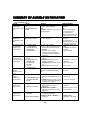
SUMMARY OF AUDIBLE NOTIFICATION........................................................................................48
FCC STATEMENTS.................................................................................................................................50
OWNER’S INSURANCE PREMIUM CREDIT REQUEST ................................................................55
LIMITATIONS OF THIS ALARM SYSTEM ........................................................................................57
INDEX ........................................................................................................................................................61
ONE YEAR WARRANTY ........................................................................................................................63
Congratulations on your ownership of a Honeywell Security System. You have made a wise
decision in choosing it, for it represents the latest in security protection technology today.
Honeywell is the world's largest manufacturer of security system, and millions of premises
are protected by Honeywell products.
–3–
–4–
SYSTEM OVERVIEW
Features
General Information
This system offers you three forms of protection: burglary, fire, and emergency, depending on the
configuration of your system. The system consists of a master keypad for controlling system operation,
various wireless sensors that provide perimeter and interior burglary protection, and optional smoke or
combustion detectors to provide early fire warning. In addition, optional wireless keypads may have
been installed to allow you to control the system away from the master keypad. The system may also be
controlled from a remote telephone and can be used as a speaker phone.
The system uses microcomputer technology to monitor all protection zones and system status, display
appropriate information on the keypad display, and initiate appropriate alarms. Your system may also
have been programmed to automatically send alarm or status messages over the phone lines to a
central alarm monitoring station, and may also be capable of two-way voice communication with the
central station. Certain features apply only to LYNXR-2SIA version of the control.
The user features of this security system are listed below. Ask your installer which features
have been programmed for your system.
• STAY and AWAY arming modes: By using these modes you can protect either the perimeter only,
or the entire premises.
• 3 panic key functions: Designated keys allow you to manually activate fire, personal emergency, or
silent alarms. Refer to the PANIC KEYS section for detailed information.
• Paging feature: If programmed by your installer this feature alerts you to certain system conditions
by displaying code numbers that indicate the type of condition that has occurred. In addition,
pressing the AUX key can send a predefined message to your pager, if programmed to do so (see AUX
key function below). Refer to the PAGING FEATURE section for detailed information.
• Follow me system announcements: Allows the LYNXR-2 Series to dial a number, programmed
by your installer, and deliver system announcements.
• Follow me reminder announcements: Allows the LYNXR-2 Series to dial a number that you
have specified, at a programmed time and day and deliver a message programmed by your installer.
• Real-time clock: Keypad displays current time. Refer to the CLOCK/CALENDAR section for
procedures for setting the time.
• Voice announcement of system status: The master keypad’s built-in speaker announces system
status at the press of a key. Refer to the CHECKING SYSTEM STATUS section for detailed
information.
• Message center: The system allows recording and play back of brief messages. Refer to the
RECORDING/PLAYBACK MESSAGES section for procedures.
• Device activation: Designated keys allow you to turn lights and/or other devices on and off. In
addition, some devices (e.g., a light) may be programmed to activate automatically as a result of a
system event such as an alarm or trouble condition. Refer to the USING POWERLINE CARRIER
DEVICE COMMANDS section for detailed information.
• AUX key function: Designated key lets you activate a predefined series of keystrokes with a single
press of the AUX key plus user code, or manually send a pager message. It will also allow you to
manually send a voice message to phone number that has been programmed by your installer. Ask
your installer which of these features has been assigned to the AUX key in your LYNXR-2. Refer to
the AUX FUNCTION section for detailed information.
–5–
SYSTEM OVERVIEW
Features
• Scheduling feature: Allows you to schedule the automatic activation or deactivation of X10 devices
or program events (e.g. alarm clock, reminder, and latch key).
• Two-way voice: Allows the central station to listen, talk to or conduct two-way conversations with
individuals on the premises Refer to the TWO-WAY VOICE section for detailed information.
• Phone Control: Provides a remote interactive phone capability that permits access to the security
system from any off-site touch-tone telephone.
• Speaker Phone Operation: The system is capable of operating as a speaker phone allowing hands
free telephone conversation.
• Security Codes: The system is capable of supporting an Installer code, Master user code and six
additional User codes including Babysitter and Duress codes. Refer to the SECURITY CODES
section for detailed information.
LYNXR-2SIA False Alarm Prevention Features
Many false alarms are caused by simple accidents, like forgetting to close a door when you leave. The
LYNXR-2SIA includes several features that help prevent false alarms and some of these are optional or
programmable. Although turning off some of these features may provide additional security, it may also
increase the chance of false alarms. Your installer can help you decide whether to use the features or
not. The following provides a brief explanation of the features included with your security system that
help prevent false alarms from occurring, and what you should do if such alarms occur.
• Exit/Entry Delays: Your security system has been programmed with delay times that allow you to
exit the premises after arming, and to disarm the system upon entry, before an alarm occurs. If you
leave the premises too late when exiting, or disarm too late when arriving home, it will cause a false
alarm. If an alarm occurs, you should disarm the system immediately, and wait for your monitoring
company to call you.
• Exit Alarms: Leaving the premises and forgetting to close the door is a common cause of false
alarms. The security system will sound an alarm, and display EA, indicating, “exit alarm”. The
security system provides extra time for you to disarm the system before dialing your monitoring
company. Disarming the system immediately may prevent a call to your monitoring company.
• Exit Time Restart-Exit Delay Restart/Reset: If you leave the premises and enter again before the
exit delay has expired, the system will restart the exit time giving you more time to leave. If there
are less than 10 seconds left to exit, the system will sound fast beeps, indicating an alarm will occur
soon if you fail to exit or disarm immediately. If this occurs, disarm the system and arm it again
when you are ready to leave. The Exit Delay can also be restarted by entering CODE + STAY.
• Auto Stay Feature: If you arm the system in the “AWAY” mode from the control’s keypad or an RF
keypad but no one exits, the alarm system will automatically change to the “STAY” mode. This will
prevent you from tripping alarms by remaining on premises. Disarm the system and arm away again
when you are ready to leave.
• Burglary Abort Window: Your security system has a delay between the time a burglary alarm
sounds, and the time the monitoring company is called. This delay gives you time to disarm the
security system before the alarm is reported to the monitoring company. This delay is factory preset
at 30 seconds, but may be increased or decreased by your installer.
• False Alarms: If a burglary or fire alarm condition occurs and the system has been disarmed, the
keypad will display “CA” or cancel. If this was a false alarm, wait for the monitoring company to call
you. They will verify your security code or password and prevent them from calling emergency
personnel to respond to a false alarm.
–6–
SYSTEM OVERVIEW
General Operation
Zones
Your system's sensing devices have been assigned to various "zones." For example, the sensing device
on your entry/exit door may have been assigned to zone 01, sensing devices on windows in the master
bedroom to zone 02, and so on. These numbers appear on the display when an alarm or trouble
condition occurs.
Fire Protection
The fire protection portion of your security system (if used) is always active and will sound an alarm if
a fire condition is detected. Refer to the FIRE ALARM SYSTEM section for important information
concerning fire protection, smoke detectors and planning emergency exit routes from the premises.
UL
LYNXR-2 Series is not intended for UL985 Household Fire applications unless a 24-hour backup
battery (P/N LYNXRCHKIT-HC) is installed.
Burglary Protection
Your system provides two modes of burglary protection: STAY and AWAY. STAY mode protects the
perimeter only, allowing you to freely move inside the premises. AWAY mode protects the entire
system. Both modes provide an entry delay time that allows you to reenter the premises without setting
off an alarm. For additional security, you can turn the entry delay off when arming the system by using
the NO DELAY key in combination with the desired arming key. The system also allows you to bypass
selected zones before arming the system, if desired. Refer to the BYPASSING PROTECTION ZONES
section. The system also provides a CHIME mode, for alerting users to the opening of protected doors
and windows while the system is disarmed.
You must turn on ("arm") the burglary protection portion of your system before it will sense burglary
alarms. To arm the system, enter your user code then press the desired arming key (AWAY or STAY).
Refer to the ARMING THE SYSTEM section for detailed procedures and information.
Security Codes
At the time of installation, you were assigned a personal 4-digit security or “master user” code. You
must enter the user code when arming and disarming the system, and when performing other system
functions. As an additional security feature, other users who do not need to know your code can be
assigned up to 6 different security codes. Refer to the SECURITY CODES section for procedures on
adding security codes to the system.
Alarms
When an alarm occurs, the keypad and external sounders will sound for about 15-seconds, and the
keypad will display the zone(s) causing the alarm. After 15-seconds, the siren stops temporarily and
voice announcements of the zones in alarm begins. When these zones have been announced, the siren
sounds again and the cycle repeats itself, until the system is disarmed (CODE + OFF) or until alarm
bell timeout occurs. If your system is connected to a central monitoring station, an alarm message will
be sent. To stop the alarm sounding, simply disarm the system. The zone(s) causing the alarm remain
displayed indicating memory of alarm. Refer to the DISARMING THE SYSTEM section for information
about clearing the memory of alarm display
–7–
SYSTEM OVERVIEW
General Operation
LYNXR-2SIA False Alarm Prevention Feature
Note that in cases of alarm, the LYNXR-2SIA may disarm as soon as the security code is entered, or
you can still enter CODE + OFF. If your system is connected to a central monitoring station, an alarm
message will be sent. To reduce false alarms, message reporting is delayed 30 seconds. The delay can be
reduced to 15 seconds, or increased up to 60 seconds at your option. Consult with your installer to
ensure that the correct delay has been programmed. To stop the alarm sounding, simply disarm the
system. The zone(s) causing the alarm remain displayed indicating memory of alarm. Refer to the
DISARMING THE SYSTEM section for information about clearing the memory of alarm display.
Two-Way Voice Feature
The LYNXR-2 Series supports voice dialog between an operator at the central station and an individual
at the premises. This feature allows the central station to listen, talk to or conduct a two-way
conversation with an individual(s) at the premises and allows the operator to gather information about
the nature and location of the alarm that may be helpful in responding to police or rescue departments.
If the Two-way Voice Feature has been programmed and an alarm condition is detected, the system
sends an alarm message to the central station. After acknowledgement is received, a “listen in to
follow” message is sent to the central station. In response to this message, the central station operator
can enter commands that allow him to initiate a 5-minute voice session. The options allow the operator
to enter the following modes:
• Talk: Allows the operator to speak to individuals at the premises through the system speaker.
• VOX (2-way voice): Allows the operator to hold a two-way (speak and listen) conversation with
individuals at the premises.
• Listen: Allows the operator to listen to any activity at the premises through the system microphone.
If a subsequent zone is violated during a voice session, the system will terminate the session and
process the alarm. During the voice session, the ARMED (red) and READY (green) LEDs will
alternately blink in the Talk and VOX Modes but not during Listen Mode.
–8–
QUICK VIEW OF SYSTEM FUNCTIONS
NOTE:
= Boxes represent the entering of your 4-digit user code.
SECURITY FUNCTIONS
Checking system status: --------------------- STATUS
To arm in STAY mode: ----------------------
*+ STAY
To restart exit delay: -------------------------
*+ STAY
To arm in AWAY mode: ---------------------
* + AWAY
To arm with NO DELAY: -------------------
* + AWAY or STAY
OR STAY
(only if programmed
and system is armed
in Stay mode.)
+
NO DELAY
To arm if Quick Arm is active: ----------- AWAY or STAY (hold down for at least 2 seconds)
+ OFF
To disarm system and silence alarms:
Note: During Entry Delay or when an Alarm Condition exists, the LYNXR-2SIA can be disarmed by entering the User
Code. Entering the OFF key is not required
+ BYPASS
To bypass a zone(s): ---------------------------
+ 2-digit zone number(s)
To turn Chime mode on or off: ----------- FUNCTION + CHIME
* Security code is not required if Quick Arm is active. Instead, press and hold down the STAY or AWAY key.
MESSAGE CENTER
To record a message: ------------------------- FUNCTION + RECORD
To stop recording before end of 85 secs: OFF
To play back a message: --------------------- FUNCTION + PLAY
To skip a message:----------------------------------- [✻]
To delete all messages: --------------------------- FUNCTION + DELETE (during message replay)
VOLUME ADJUSTMENT
To adjust message playback/announcement volume:
FUNCTION
+
VOLUME + [3] or [6]
To mute system announcements: ------- FUNCTION + VOLUME + OFF
To restore/unmute announcements:---- FUNCTION + VOLUME + [3] or [6]
SPEAKER PHONE OPERATION
To enter speaker phone mode: ----------- [#] + AUX
To exit speaker phone mode: ------------- OFF
To enable/disable (toggle) ringer: ------ [#] + VOLUME + AUX
To return keypad to telephone mode (after clearing an alarm or trouble or disarming the system): [#] + AUX
To flash (switch back and forth between two calls using call waiting): AUX
(wait at least two (2) seconds before pressing AUX again)
–9–
QUICK VIEW OF SYSTEM FUNCTIONS
REMOTE PHONE CONTROL OPERATION
To remotely disarm: ---------------------------------
+ [1]
To remotely arm in AWAY mode: --------------
+ [2]
To remotely arm in STAY mode: ---------------
+ [3]
+ [2] or [3] + [0]
To remotely arm in AWAY or STAY mode with NO DELAY:
To remotely activate X10 devices 01-06: ---- [#] + [4] + (2-digit) device no.
+ [#] + [4] + (2-digit) device no.
To remotely activate X10 devices 07 & 08:-
To remotely deactivate X10 devices 01-06: [#] + [7] + (2-digit) device no.
+ [#] + [7] + (2-digit) device no.
To remotely deactivate X10 devices 07 & 08:
To remotely bypass a zone: ----------------------
+ [6] + zone no.
To remotely activate forced bypass: ---------
+ [6] + [#]*
To remotely check system status: ------------- [*]
+ [9]
To hang up: ---------------------------------------------*If forced bypass was enabled by your installer.
OTHER FUNCTIONS
To set the time and date: --------------------------
+ FUNCTION
+ [63]
To set scheduling: ------------------------------------
+ FUNCTION
+ [64]
To activate X10 devices 01-06: ------------------- FUNCTION + LIGHTS ON + (2-digit) dev. no.
+ FUNCTION + LIGHTS ON + (2-digit) dev. no.
To activate X10 devices 07 & 08:
To deactivate X10 devices 01-06:................... FUNCTION + LIGHTS OFF + (2-digit) dev. no.
+ FUNCTION + LIGHTS OFF + (2-digit) dev. no.
To deactivate X10 devices 07 & 08:
To add a user code:
** + CODE + user no. (02-08)+ user code
To delete a user code (except Master Code): .....
** + CODE
To turn Test mode on: ------------------------------
+ TEST
To turn Test mode off: -----------------------------
+ OFF
+ user number (02-08)
To use the defined AUX function: - Press and hold AUX key 2 seconds (4 beeps) +
To send message to pager: ------------ Press and hold AUX key 2 seconds (4 beeps)
+ FUNCTION + [65] + Enter up to 24
To program “Follow Me” reminder phone no:
digits
+
To delete “Follow Me” reminder phone no:
** Only the master code can be used to add or delete another user code.
– 10 –
FUNCTION
+ [65]
SYSTEM OVERVIEW
About the Master Keypad
General
IMPORTANT: If the keypad beeps rapidly upon entering the premises, an alarm has occurred during
your absence and an intruder may still be on the premises. LEAVE IMMEDIATELY and CONTACT
THE POLICE from a nearby safe location.
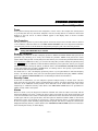
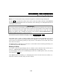
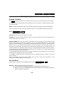
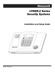
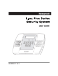
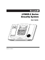
The keypad allows you to control all system functions. In the speaker phone mode the keypad becomes
a full-function telephone keypad. The keypad features telephone-style keys and a Liquid Crystal
Display (LCD), which shows the nature and location of all occurrences.
09015-001-V0
The keypad also features a built-in sounder, which will sound during alarms and troubles. The keypad
also "beeps" during certain system functions, such as during entry/exit delay times, in Chime mode,
and when depressing any of the keys (to acknowledge the key press). In addition, a built-in speaker
announces system status.
The voice announcement volume is adjustable, however the “beeps” that sound in response to alarms
always sound at the maximum volume level. All other “beeps” (trouble, chime, exit/entry, etc) can be set
to either low or high volume.
– 11 –
SYSTEM OVERVIEW
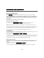
Master Keypad Definitions
20
21
3
2
1
4
19
5
ARMED
READY
1
2
3
ESCAPE
RECORD
VOLUME
PLAY
AWAY
4
5
6
LIGHTS ON
TEST
BYPASS
6
OFF
18
ADD
7
8
9
LIGHTS OFF
CODE
CHIME
STATUS
NO DELAY
STAY
DELETE
17
8
0
AUX
SELECT
7
FUNCTION
9
16
15
14
11
12
13
10
09015-003-V0
IMPORTANT!
When you use the keypad to enter codes and commands, press the keys within 2 seconds of one another. If 2
seconds elapse without a key depression, the entry is aborted and must be repeated from its beginning.
NOTE: Different timeouts may occur when defining auxiliary functions and setting the real-time clock.
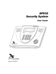
Note: The system functions described below are for reference only and require additional key entries to activate.
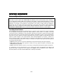
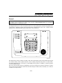
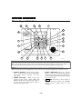
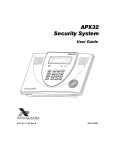
1. DISPLAY WINDOW: Liquid Crystal Display
(LCD). Displays protection point identification
and system status, messages, and user
instructions.
2. ARMED INDICATOR: (RED) Lit when the
system has been armed (STAY, AWAY, NO
DELAY). Blinks when armed and fault exists, or
once per second when AVM (VOX or Talk) or
speaker phone mode is active.
– 12 –
3. READY INDICATOR: When lit, indicates
system is ready to be armed; blinking indicates
system is not ready (a zone is open). Blinks once
per second when AVM (VOX or Talk) or speaker
phone mode is active.
4.
PLAY
KEY: Announces a user’s message if
one was previously recorded. See RECORD
function. Used to adjust volume of voice
messages.
SYSTEM OVERVIEW
Master Keypad Definitions
5.
TEST
15. STAY
KEY: Tests the system and alarm
sounder.
6.
BYPASS
CODE
KEY: Removes individual protection
KEY: Allows entry of additional user
codes that can be given to other system users.
8.
CHIME
16. AWAY
KEY: Turns the Chime mode on and
off. When on, any entry through a protected
delay or perimeter zone while the system is
disarmed will cause a tone and voice descriptor
to sound at the keypad.
9. INTERNAL SOUNDER: Source of alarm sounds
(see "Summary of Audible Notifications" section).
10. FUNCTION
KEY:
Allows
alternate
key
functions. It is used as a “repeat” key during
Clock/Calendar setting.
11. NO DELAY
KEY: When pressed prior to arming,
the keypad will display all open zones, and will
announce system status.
13. LIGHTS ON
/
LIGHTS OFF
KEYS:
Turns
lights or other devices on or off, if programmed by
the installer.
14. AUX
/ SELECT
KEY: Can be programmed
/
ADD
KEY: Completely arms both
perimeter and interior burglary protection for
backup protection by sensing an intruder's
movements through protected interior areas as
well as guarding protected doors, windows, etc.
Entrance can be made through an entry delay
zone without causing an alarm if the system is
disarmed before the entry delay time expires.
Used to accept “Follow Me” phone number and
Clock/ Calendar mode entries.
17. OFF
KEY: Used with STAY or AWAY
function to eliminate the entry delay. Alarm
sounds immediately if entry is opened.
12. STATUS
KEY: Arms the perimeter
burglary protection, guarding protected doors,
windows and other perimeter protection points,
and sounds an alarm if one is opened. Interior
protection is not armed, which allows movement
within your house without causing an alarm.
Entrance can be made through an entry delay
zone without causing an alarm if the system is
disarmed before the entry delay time expires.
Used to delete messages.
zones from being monitored by the system.
Displays currently bypassed zones.
Used to adjust volume of voice messages.
7.
/ DELETE
/ ESCAPE
KEY: Disarms the burglary
portion of the system, silences alarms and
audible trouble indicators, and clears alarm
trouble display after the problem has been
corrected. Used to exit/abort “Follow Me” phone
number and Clock/Calendar mode.
18. MICROPHONE: Used to record personal
messages up to 85 seconds long, and for 2 way
voice and speaker phone.
19. SPEAKER: Source of audible internal warning
and confirmation sounds, status announcements,
as well as alarms (see "Summary of Audible
Notifications").
20. RECORD: Activates the recording function to
record personal messages.
to either perform a predefined function or to send
a preset message to a pager or a “Follow Me”
system phone number.
21. VOLUME:
Sets
the
volume
announcements and status beeps.
of
system
–– KEYS 0-9:
Used to enter your individual
security access code(s).
– 13 –
SYSTEM OVERVIEW
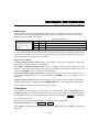
About the Display and Indicators
AWAY
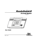
Display Definitions (for other displays, see Trouble Messages)
ALARM:
AWAY:
INSTANT:
STAY:
UL
LOW BAT AC
INSTANT CHIME TEST
ALARM
STAY REC MESSAGE
FIRE BYPASS FAULT
Appears when the system is armed and an intrusion has been detected (also appears
during a fire alarm or audible emergency alarm). Accompanied by the protection zone
that is in alarm.
All burglary zones, interior and perimeter, are armed.
Entry delay is turned off.
Perimeter burglary zones, such as protected windows and doors, are armed.
LYNXR-2 Series is not intended for UL985 Household Fire applications unless a 24-hour backup
battery (P/N LYNXRCHKIT-HC) is installed.
FIRE:
LOW BAT:
AC:
CHIME:
TEST:
Appears when a fire alarm or fire fault is present. Accompanied by a display of the
zone that is in alarm.
Low battery condition in a wireless sensor (if zone number is displayed) or low system
battery (if no zone number is displayed). If 00 is displayed, a wireless keypad (5827)
has a low battery condition.
Appears when AC power is present. If not displayed, the system is operating on
backup battery power.
Appears when the Chime feature is activated.
Appears when the system is in Test mode.
LYNXR-2SIA blinks during the last 5 minutes of test.
REC:
MESSAGE:
BYPASS:
FAULT:
PH:
PC:
Appears when the system is in Recording mode.
Appears when a message has been recorded and has not yet been played back.
Appears when one or more burglary protection zones have been bypassed.
Appears at any time a malfunction is discovered in the system; or any time an open
is detected in a fire zone; or when a fault in a day/night burglary zone is discovered
during a disarmed period. Accompanied by a display of the zone number in trouble.
Appears in place of the clock when the speaker phone mode is active.
Appears during a remote phone control session.
LED Meanings
ARMED LED:
(Red)
READY LED:
(Green)
ON = System armed
OFF = System disarmed
Blinking = System armed, but a fault exists
Blinking alternately with READY LED = AVM (VOX or Talk) or speaker phone mode
is active
ON = System disarmed, ready to arm
OFF = System armed
Blinking = System disarmed, not ready to arm (a fault exists)
Blinking alternately with ARMED LED = AVM (VOX or Talk) or speaker phone
mode is active.
– 14 –
SECURING THE PREMISES
Checking System Status
General Information
Before arming your system, all protected doors, windows, and other protection zones must be closed or
bypassed (see the BYPASSING PROTECTION section). Pressing the STATUS key will announce all
zones that are faulted, as well as any other abnormal system condition, making it easier for you to
secure any open zones.
READY LIGHT: The green READY indicator on the keypad will be lit if the system is ready to be
armed. If blinking, the system is not ready.
Press the STATUS Key
Press the STATUS key once to announce the general status of the system.
Depending on the current state of the system the following phrases may be heard:
disarmed, ready to arm [message] [check system]
disarmed, [not ready to arm], [message]
armed [away] [stay] [instant] [check system] [message]
NOTE: The phrases shown in brackets are variable, and are announced only if appropriate in the current state of the
system.
†
Press the STATUS key a second time to announce specific system status.
Depending on the current state of the system the following phrases may be heard:
fire alarm [zone voice descriptors]
carbon monoxide alarm [zone voice descriptors]
alarm [zone voice descriptors]
fire fault [zone voice descriptors]
carbon monoxide fault [zone voice descriptors]
fault [zone voice descriptors]
low battery [zone voice descriptor]
system low battery
check system
AC loss
zones bypassed
chime
† (second depression must be made within 10 seconds of the first)
VOLUME LEVEL: The volume level of system announcements can be increased or decreased. Refer to
the MESSAGE RECORDING/PLAYBACK section for the procedure.
System Can Be Armed
The READY LED will be lit once all protection zones have been closed or bypassed. You may now arm
the system as usual.
– 15 –
SECURING THE PREMISES
Arming the System
Arming in Stay Mode
Use this mode when you are staying home, but expect someone to use the entrance door later. Close all
protected perimeter windows and doors before arming. The green READY indicator on the keypad
should be lit if the system is ready to be armed.
+ STAY
To arm in STAY mode:
or press and hold STAY **
Your User code**
** See Quick Arming paragraph.
The keypad beeps three times and displays the armed STAY message. The red ARMED indicator lights
and the system announces “armed STAY–exit now.”
When armed in STAY mode, the system will sound an alarm if a protected door or window is opened,
but you may otherwise move freely throughout the premises. Late arrivals can enter through the
entrance door without causing an alarm, but they must disarm the system within the entry delay
period or an alarm will occur.
Restarting Exit Delay While System Armed
Ask your installer if this feature is active for your system. If active, you can restart the exit delay at
any time after arming in STAY mode by entering the User Code and pressing the STAY key, or simply
by pressing the STAY
key by itself. This avoids having the user disarm then re-arm the system after
allowing someone to enter or exit.
Exit Delay Restart/Reset
On the LYNXR-2SIA, this option also enables automatic exit delay reset, which resets exit delay if the
entry/exit door is re-opened and closed before exit delay time expires after arming. Automatic Exit
Delay Reset occurs only once during an armed period.
To restart exit delay while system is armed in STAY mode: Press STAY key.
Arming In Away Mode
Use this mode when no one will be staying on the premises. Close all protected perimeter windows and
doors before arming. The green READY indicator on the keypad should be lit if the system is ready to
be armed.
+ AWAY
To arm in AWAY mode:
or press and hold AWAY **
Your User Code **
** See Quick Arming paragraph.
The keypad beeps twice, or beeps continuously if exit warning has been programmed for your system,
and displays the armed AWAY message. The red ARMED indicator lights and the system announces
“armed AWAY–exit now.”
When armed in AWAY mode, the system will sound an alarm if a protected door or window is opened,
or if any movement is detected inside the premises. You may leave through the entrance door during
the exit delay period without causing an alarm. You may also re-enter through the entrance door, but
you must disarm the system within the entry delay period or an alarm will occur.
– 16 –
SECURING THE PREMISES
Arming the System
Auto Stay Feature
If this feature is enabled by installer, the LYNXR-2SIA, when armed AWAY from the control’s keypad
or a Wireless Keypad, switches to the STAY mode if the Exit Time expires and no exit has been made.
NOTE:
If the exit route entry/exit sensor is in a check condition or has been bypassed it will result in a loss of interior
protection because the alarm system will arm STAY in this case. Consult with your installer for servicing of the
entry exit zones or to turn off this feature if a check condition on entry exit zones occurs.
Arming the System with No Delay
Use NO DELAY with STAY mode when you are staying home and do not expect anyone to use the
entrance door.
Use NO DELAY with AWAY mode when the premises will be vacant for extended periods of time such
as vacations, etc.
When armed with NO DELAY, the system will sound an alarm if a protected door or window is opened,
including the entrance door. You may leave through the entrance door during the exit delay period
without causing an alarm, but an alarm will sound as soon as someone reenters.
+ AWAY or STAY
To arm with NO DELAY:
+
NO DELAY
Your user code**
** See Quick Arming paragraph.
Quick Arming
If Quick Arm was programmed by the installer, you do not need to enter the security code to arm the
system. Instead, simply press and hold down the desired arming key for at least 2 seconds. The
security code must always be used to disarm the system, however.
To arm if Quick Arm is active:
AWAY or STAY
hold down for at least 2 seconds
To arm with NO DELAY if Quick Arm is active:
AWAY or STAY
then NO DELAY hold down for at
least 2 seconds
IMPORTANT: The Babysitter Code and Installer Code cannot disarm the system unless it was used to
arm the system. In addition, if the system is armed by pressing and holding the Quick-Arm buttons,
neither the Babysitter Code nor Installer Code can disarm the system.
– 17 –
SECURING THE PREMISES
Entry/Exit Delays
Exit Delay
Exit delay begins immediately after arming the system, and gives you time to leave through the
designated exit door without setting off an alarm. A slow beeping will sound throughout the exit delay
period, if programmed. During the last 10 seconds of the exit delay fast beeps will sound as a warning
that the delay time is nearing its end. The exit beeps cannot be silenced.
Exit Alarms
Exit Alarm Active
To minimize false alarms sent to the alarm monitoring company, your system may have been
programmed for this feature. Ask your installer if Exit Alarm is active for your system.
Whenever you arm the system, the exit delay begins. If an entry/exit door or interior zone is faulted
when the exit delay ends (e.g., exit door left open), the system sounds an alarm and starts the entry
delay timer. If you disarm the system before the entry delay ends, the alarm sound stops and the
message "CA" is displayed on the keypad, along with a zone number indicating the faulted zone. No
message is sent to the alarm monitoring company. To clear the exit alarm condition, the open zone
must be made re-secured; to clear the display, enter your security code and press the OFF key.
If you do not disarm the system before the entry delay ends, and an entry/exit door or interior zone is
still open, the alarm sound continues and an "exit alarm" message is sent to the alarm monitoring
company. The message "EA" is displayed on the keypad, along with a zone number indicating the
faulted zone. The alarm will continue to sound until the system is disarmed or timeout ocurs. To stop
the alarm, the system must be disarmed by entering your security code and pressing the OFF key; and
the message "CA" is displayed on the keypad, indicating that the alarm has been cancelled (if this
feature is enabled by the installer). To clear the display, enter your security code and press the OFF
key a second time. An exit alarm also results if an entry/exit door or interior zone is faulted within two
minutes after the end of the exit delay.
Entry Delay
Entry Delays give you time to disarm the system when you re-enter through the designated entrance
door. You must disarm the system before the entry delay period ends, or an alarm will occur. The
keypad beeps during the entry delay period, reminding you to disarm the system. There are two entry
delays (if programmed). The first is for your primary entrance and the second can be used for a
secondary entrance, where a longer delay is required to walk to the keypad to disarm the system. You
can also arm the system with no entry delay at all by using the NO DELAY key when arming. This can
provide greater security while on the premises or while away for extended periods of time. See
ARMING THE SYSTEM section for procedure. See your installer for delay times programmed for your
system.
Exit Delay:
00-99 seconds
Entry Delay 1:
00-99 seconds
Entry Delay 2:
00-99 seconds
Entry Delay 2:
30-96, 120, 180, 240 seconds
LYNXR-2SIA Exit/Entry Delay Times
Exit Delay:
45-96, 120 seconds
Entry Delay 1:
30-96, 120, 180, 240 seconds
– 18 –
SECURING THE PREMISES
Disarming the System
NOTE: The control will provide a long confirmation ding when it is disarmed using an RF Key Fob.
Use the OFF key to disarm the system and to silence alarm and trouble sounds. See the SUMMARY
OF AUDIBLE NOTIFICATION section for information, which will help you to distinguish between fire
and burglary alarm sounds.
**IMPORTANT**
If you return and the main burglary sounder is on, DO NOT enter the premises, but call the police
from a nearby safe location. If you return after an alarm has occurred and the main sounder has shut
itself off, the keypad will beep rapidly upon entering. This indicates that an alarm has occurred
during your absence and an intruder may still be on the premises. LEAVE IMMEDIATELY and
CONTACT THE POLICE from a nearby safe location.
+ OFF
To disarm the system and silence burglary alarms:
Your user code
During Entry Delay or when an Alarm Condition exists, the system will be disarmed as soon as the
correct user code is entered on the keypad. Entering the OFF key is not required. The entry beeps or
alarm sound can be silenced by pressing any key however, it will restart in 10 seconds if the correct
User Code is not entered.
The READY indicator will light (if no alarms have occurred while armed) and the keypad will beep once
to confirm that the system is disarmed.
Memory of Alarm
If an alarm occurs, the keypad displays the zone number (s) that caused the alarm and the type of
alarm (e.g., “FIRE ALARM”). These messages remain displayed until cleared by a user.
To clear the display, note the zone number displayed and enter an OFF sequence (enter your security
code and press the OFF key).
If the READY indicator is blinking, go to the displayed zone and correct the fault (close windows, etc.).
If the fault cannot be corrected, notify your alarm company.
– 19 –
SECURING THE PREMISES
Bypassing Protection Zones
Bypassing Individual Zones
Use the BYPASS key when you want to arm your system with one or more zones intentionally
unprotected. Bypassed zones are unprotected and will not cause an alarm when violated while your
system is armed. All bypasses are removed when an OFF sequence (security code plus OFF) is
performed. Bypasses are also removed if the arming procedure that follows the bypass command is
not successful.
The system will not allow fire zones to be bypassed.
The system must be disarmed first.
+ BYPASS + 2-digit zone number(s) for zone(s) to be
To bypass a zone(s):
Your user code
bypassed (e.g., 02, 03, etc.)
Important! All single-digit numbers must be preceded by a zero (for example, enter 02 for zone 2).
The keypad will provide a confirmation beep and display the word “BYPASS” along with each bypassed
zone number. Wait for these zones to be displayed, to be sure that intended zones are bypassed.
Arm the system as usual when the keypad displays the READY LED on steady.
Forced Bypass
Your system may allow you to easily bypass all open (faulted) zones without having to enter zone
numbers individually. Ask your installer if this feature is active.
+ BYPASS + FUNCTION
To bypass a zone(s):
Your user code
In a few moments, all open zones will be displayed along with the word “BYPASS.” Wait for these zones
to be displayed before arming. Arming the system before zones are displayed eliminates all bypasses.
Arm the system as usual when the keypad displays the READY LED on steady.
Displaying Bypassed Zones
The system allows you to determine what zones have been previously bypassed. Bypassed zones can be
displayed only when the system is disarmed, and when the “BYPASS” message described above is
displayed.
+ BYPASS + WAIT
To display bypassed zone(s):
Your user code
In a few moments, all open zones will be sequentially displayed along with the word “BYPASS.”
– 20 –
SECURING THE PREMISES
Panic Keys / Chime Mode
Panic Keys
Your system may have been programmed to use special keys to manually activate panic functions. The
functions that might be programmed are listed below. See your installer for the function(s) that may
have been programmed for your system.
Active Panic Functions
Your installer should
note the functions that
are active in your
system.
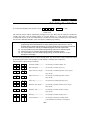
Keys
1 and ✻
3 and #
✻ and #
Zone
95
96
99
Function
To use a paired key panic function, simply press both keys of the assigned pair at the same time. If
your keypad has lettered keys for panic functions, press the designated key and hold down for at least 2
seconds to activate the panic function. Panic keys can also be activated by wireless devices such as the
Ademco 5827. Ask your installer about this feature.
Types of Panic Alarms
A silent emergency/silent alarm sends an alarm signal to the alarm monitoring company,† but
there will be no audible alarms or visual displays.
An audible emergency/audible alarm sends an emergency message to the alarm monitoring
company† and sounds a loud, steady alarm at your keypad and at any external sounders that may be
connected (“ALARM” plus a zone number are also displayed).
A personal emergency/aux alarm sends an emergency message to the alarm monitoring company†
and sounds at keypads, but not at external sounders. (“ALARM” plus a zone number are also
displayed).
A supervised fire alarm sends a fire alarm message to the alarm monitoring company† and uniquely
activates keypad and any external sounders (“FIRE ALARM” plus a zone number are also displayed).
† If your system is connected to an alarm monitoring company
Chime Mode
Your system can be set to alert you to the opening of a door or window, while it is disarmed, by using
CHIME mode. When activated, three beeps will sound at the keypad whenever a protected perimeter
door is opened and the zone voice descriptor will be announced. Pressing the STATUS key will display
the open protection points.
Note that the Chime mode can be turned on only when the system is disarmed.
To turn Chime mode on or off: FUNCTION + CHIME
The “CHIME” message displays while Chime mode is on, and disappears from the display when Chime
mode is off.
– 21 –
USER FUNCTIONS
Paging Feature
Automatic Paging
If the Paging feature has been programmed for your system, your pager will respond to certain
conditions as they occur in your system by displaying a message that indicates the type of condition
that has occurred. The message appears in a 7-digit format explained below. The system can also be
programmed to send up to 16 additional digits that will appear in front of the 7-digit message. These 16
digits may consist of a PIN number or special digits needed by the pager, account number, pauses, or
any other special characters you may choose (for example, you may want to use a special character code
to distinguish between security system messages and usual pager messages). See your installer if these
additional characters are desired.
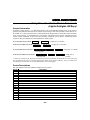
Code Format
The Pager Code takes the following form: (AAAAAAAAAAAAAAAA) EEE-0NNN
AAA… = Optional 16 digits, programmed by your installer.
EEE = 3-digit number describing the event that has occurred, as follows:
911 = Alarm (00NN following indicates the zone that caused the alarm)
101 = Open, system disarmed (00NN following indicates user number)
102 = Close, system armed (00NN following indicates user number)
811 = Trouble (00NN following indicates the zone that caused the trouble)
0NNN = First digit is always 0, followed by 3-digit user or zone number, depending on the
type of event that occurred. If NN = 00, it can mean an AC loss has occurred, the
system battery is low, or a 5827 wireless keypad battery is low. The Master Keypad
will indicate the specific condition.
Examples:
Pager displays: 911–0004
This indicates your system is reporting an alarm (911) due to a fault on zone 4 (0004).
Pager displays: 101–0005
This indicates that your system is reporting an open/disarm (101) by user 5 (0005).
Manual Paging
In addition, your system may have been programmed to send a unique pager message when the AUX
key is pressed (see AUX FUNCTION section for alternate function of this key). The actual message sent
is 999-9999 (the hyphen may not appear, depending on your pager service). This code can be used to
alert the person with the pager to whatever meaning you pre-arrange (e.g., “call home”). Ask your
installer if this has been done for your system.
To manually send the pager message, if programmed: AUX (hold until 4 beeps sound)
– 22 –
USER FUNCTIONS
“Follow Me” Announcement Feature
“Follow Me” Reminder and System Announcements
If the “Follow Me” Announcement feature has been programmed your system will automatically dial a
telephone number and deliver a voice message. The two different types of “Follow Me” messages include
system and reminder announcements.
System Announcements
LYNX can be programmed to trigger “Follow Me” system announcements by one or a combination of
the following events:
•
Alarm
•
Trouble
•
Arming/Disarming (by a keyfob or users 5-8*)
*see Security Codes section for user code descriptions.
Ask your installer about the events that trigger “Follow Me” system announcements.
“Follow me” system announcements are delivered to a phone number that has been programmed by
your installer. The voice message is a repeatable system status message (i.e. “Disarm Ready to Arm”
when system was disarmed; “Armed Away” when system was armed; “Alarm Front Door” when an
alarm occurred, etc). In addition, a special repeatable voice message (“System, System…”) can be
triggered manually by pressing the AUX key on the keypad and holding it down for 4 seconds.
NOTE: This is similar to the manual paging feature (see Paging Feature for details).
Reminder Announcements
The “Follow me” reminder announcement is triggered by the scheduler if Reminder Announcements
has been chosen as Event Identifier (see Scheduling User interface for details).
NOTE: The “Follow me” reminder can only be used if the “Follow me” or Pager feature has been
programmed by your installer.
The “Follow me” reminder voice message is the same reminder that is played through a local speaker.
The reminder should be recorded by your installer. The “Follow me” reminder message will be delivered
to a phone number that your installer has programmed or that you can program by yourself. If the
“Follow me” reminder phone number has not been programmed, or has been deleted, the reminder is
announced through a local speaker only.
After the “Follow me” system or reminder announcement is delivered you can terminate it by pressing
any key on the telephone keypad. If the message is not acknowleged/terminated LYNXR-2 Series will
attempt to deliver the message and will redial the “Follow Me” telephone number a maximum of eight
times.
– 23 –
USER FUNCTIONS
“Follow Me” Announcement Feature
NOTES: (1) The “Follow Me” announcement will be terminated if any new report needs to be sent or if
any key is pressed on the LYNXR-2 Series keypad or a wireless (RF) keypad. The [✻] key on
a wireless keypad is ignored by the system when the “Follow me” feature is active and
cannot be used to terminate the announcement or request status.
(2) If your LYNXR-2 Series has been programmed to send “Follow Me” system messages upon
arming/disarming do not make any key strokes after you have disarmed the system (unless it
is necessary). Entering additional keystrokes will terminate the “Follow Me” message.
To program “Follow Me” reminder telephone number:
+ FUNCTION
+ [65]
1.
Enter:
2.
The system will announce: “Enter follow me reminder phone number, press ADD to accept, press
ESCAPE to quit”.
Master user code
NOTES: (1)
The system will accept all digits including the star [✻], pound [#]. To insert a two (2) second pause
press the AUX key.
(2)
If the ESCAPE
(3)
Pressing any key on a wireless (RF) keypad will terminate this mode and the “Follow Me” telephone
number must be reentered.
key is pressed to cancel entry, the telephone number must be entered again.
3.
Enter up to 24 digits. After each digit is entered the system will announce the digit and it will be
displayed on the LCD screen. The system will not announce star, pound or pause, however “Str,
Pnd, or PAU will be displayed on the LCD screen.
4.
After you have entered the last digit press ADD to save the number. If 24 digits have been
entered the system will automatically save the number and exit the “Follow Me” announcement
feature.
NOTE: The “Follow me” reminder telephone number can be changed as often as necessary by repeating
steps 1 through 4.
To delete “Follow Me” reminder telephone number
+ FUNCTION + [65]
1.
Enter:
2.
Master user code
The system will announce: “Enter follow me reminder phone number, press ADD to accept, press
ESCAPE to quit”.
3.
Press ADD without entering any digits.
– 24 –
USER FUNCTIONS
General Information
Using Powerline Carrier Device Commands
(Lights On/Lights Off Keys)
Powerline Carrier devices (e.g. X10 brand devices) are programmable switches that can be used to
perform many different functions. Your system may be set up so that certain lights or other devices can
be turned on or off by using the device command from the keypad. Ask your installer if this has been
done in your system. If programmed for your system, some devices may activate automatically upon
certain system conditions. In this case, the following commands can be used to override the device
activation. See your installer for a full explanation of this feature.
To activate X10 devices 01-06: FUNCTION
+
To deactivate X10 devices 01-06: FUNCTION
LIGHTS ON
+
+ (2-digit) dev. no. (2 beeps)
LIGHTS OFF
+ (2-digit) dev. no. (2 beeps)
+ FUNCTION + LIGHTS ON + (2-digit) dev. no. (2 beeps)
To activate X10 devices 07 & 08**:
Your user code
+ FUNCTION + LIGHTS OFF + (2-digit) dev. no.
To deactivate X10 devices 07 & 08**:
Your user code
(2 beeps)
** Devices 07 and 08 may be assigned to system devices, such as alarm bells, which should not be activated using
this command because they are activated automatically under certain system conditions. See your installer and
the table below. Devices 09-16 are used for Multi-Mode (e-mail event triggers.
Device Descriptions
See your installer for device numbers assigned for your system.
Device
01
02
03
04
05
06
07
08
09
10
11
12
13
14
15
16
Description
– 25 –
USER FUNCTIONS
Message Recording/Playback/Volume Control
The LYNXR-2 Series Message Center allows you to record, play and delete messages. The maximum
message duration is 85 seconds.
NOTES: (1) The Record/playback functions can only be performed from the master keypad. It cannot be
performed from any other wireless keypad (ex. 5827).
(2) If the system loses electrical power, all messages will be erased.
(3) Message Play/Record will not be available if a report must be sent.
(4) Individual messages cannot be played back or deleted.
Recording a Message
To record a message: FUNCTION + RECORD
The keypad displays “REC MESSAGE.” Begin speaking into the microphone.
The recording will automatically stop after 85 seconds, if a message has been recorded. The keypad will
beep twice and “REC” will no longer be displayed. “MESSAGE” will still be displayed.
To stop recording before the end of 85 seconds: Press OFF
The keypad beeps twice, the REC display turns off, but the MESSAGE display remains on.
Additional messages can be recorded, as long as there is recording time remaining, by repeating the
above steps.
NOTE: If you are trying to record a new message and the message center is already full, the system will
announce “END MESSAGE” and “REC MESSAGE” will not be displayed. If the message center is
full all old messages must be deleted before new messages can be recorded. See Deleting
Messages section.
Message Playback
The lighted word MESSAGE indicates that a new message is in memory. After playing the message,
the MESSAGE display turns off. See NOTE below if using a wireless keypad.
To play back a message: FUNCTION + PLAY
All recorded messages will be announced sequentially. A short beep will sound between messages.
To skip a message: Press [✻]
Deleting Messages
To delete all messages: FUNCTION + PLAY
While the messages are being announced: Press FUNCTION + DELETE
A double beep will sound confirming that the messages have been deleted.
– 26 –
USER FUNCTIONS
Message Recording/Playback/Volume Control
Adjusting the Volume
The volume level of message playback, system announcements, and status beeps can be changed. You
can also mute system announcements if desired. See NOTE below if using a wireless keypad.
To adjust message playback/system announcement volume:
FUNCTION
+ VOLUME + [3] or [6] †
† [3] = increases volume one level, [6] = decreases volume one level.
Repeat the key sequence until the desired volume level is achieved.
To mute system announcements: FUNCTION + VOLUME + OFF
When muted, no system announcements will be made. Recorded messages will be announced, though,
when PLAY is pressed.
To restore announcement sounding: FUNCTION + VOLUME + [3] or [6]
Volume level will be restored to the level that was selected prior to muting the sound.
NOTE: If a wireless keypad (5827) has been installed and is programmed for quick arming, it cannot be
used to activate message playback or adjust the volume. In this case, you must use the master
keypad to perform these functions.
– 27 –
USER FUNCTIONS
AUX Function
General Information
The AUX key may have been programmed to either perform a predefined function or to send a preset
message to a pager/”Follow Me” system phone number (see Pager Feature section for pager operation or
the Follow Me Announcement Feature section for “Follow Me” operation). Ask your installer which
function has been assigned for your system.
AUX Key:
PRE-DEFINED FUNCTION
PAGING FUNCTION
FOLLOW ME VOICE MESSAGE
If programmed for the AUX function, you can use the AUX key to activate a string of up to 20
keystrokes that have been stored in the system’s memory. Typical functions include:
• Seldom used but repeatable sequences
• Arming sequences that involve bypassing zones before arming
• Device activation sequences
Defining the AUX Function
The system must be disarmed before defining a function.
1.
+ FUNCTION
Enter
+ AUX (hold down at least 2 seconds until 4 beeps sound).
Master user code
2.
Press the desired command sequence, up to 20 keystrokes. Press the AUX key between each
command in the sequence.
3.
Press the AUX key twice to end the definition.
For example, to bypass Zones 10 and 11 and arm AWAY with NO DELAY, enter the following string:
+ FUNCTION + AUX + [6] + [10] + [11] + AUX + AWAY + [0] + AUX + AUX
Master user code
Note that the AUX key is included in the 20 keystroke maximum.
Performing the AUX function
Press and hold down the AUX key (hold down at least 2 seconds until 4 beeps sound), then enter
The defined function will begin.
Your user code
– 28 –
USER FUNCTIONS
Clock/Calendar
Your system can display the current time (see your installer). The date is not displayed, but has an
internal function. The system must be disarmed.
+ FUNCTION
To set the time and date:
+ [63]
Master user code or
Installer Code
The system will enter the Voice Prompt Calendar Setting mode. The [#] key can be pressed at
any time to repeat a voice prompt.
NOTES: (1) The keypad beeps twice for invalid data entries (e.g., an hour greater than 12), and the entry
will not be accepted. The keypad beeps once for valid entries.
(2) Clock-Setting mode automatically ends if no keys are pressed for one minute.
(3) It is not possible to enter the real time clock programming mode from a wireless keypad
(4) Pressing any key on a wireless (RF) keypad terminates Clock/Calendar setup.
(5) It is not possible to enter the real time clock programming mode when either FC or CA is
displayed on the display.
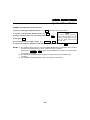
1.
The system will announce, “Enter two-digit hour then press ADD to accept, ESCAPE to quit”.
Hour 12 : A (The current hour will be displayed with the AM/PM indication.)
Enter the 2-digit hour (i.e., 01-12).
Press [ADD] to accept the entry and continue to the AM/PM selection.
Press [ESCAPE] to exit Clock/Calendar mode (keypad beeps 4 times).
2.
The system will announce, “Enter one for PM, zero for AM, press ADD to accept, ESCAPE to quit”.
AM/PM 12: P (The current AM/PM setting will display A or P.)
Enter 1 for PM or 0 for AM.
Press [ADD] to accept the entry and continue to the minute selection.
Press [ESCAPE] to back up to hour selection.
3.
The system will announce, “Enter two-digit minute press ADD to accept, ESCAPE to quit”.
Minute
: 25 (The current minute will display.)
Enter the 2-digit minute (i.e., 00-59).
Press [ADD] to accept the entry and continue to the month selection.
Press [ESCAPE] to back up to AM/PM selection.
4.
The system will announce, “Enter two-digit month press ADD to accept, ESCAPE to quit”.
Month
1
(The current month will display.)
Enter the 2-digit month designation (i.e., 01-12).
Press [ADD] to accept the entry and continue to the day selection.
Press [ESCAPE] to back up to Minute selection.
– 29 –
USER FUNCTIONS
Clock/Calendar
5.
The system will announce, “Enter two-digit day press ADD to accept, ESCAPE to quit”.
Day
01 (The current day of the month will display.)
Enter the 2-digit day of the month (i.e., 01-31).
Press [ADD] to accept the entry and continue to the year setting.
Press [ESCAPE] to back up to Month selection.
6.
The system will announce, “Enter two-digit year press ADD to accept, ESCAPE to quit”.
Year
05
(The current year will be displayed.)
Enter the last two digits of the year (i.e., 00-99).
Press [ADD] to accept the entry and exit Clock-Setting mode (keypad beeps 4 times).
Press [ESCAPE] to back up to Day selection.
– 30 –
USER FUNCTIONS
Scheduling User Interface
+ FUNCTION + [64]
To access the Scheduling User Interface enter:
Master user code or
Installer Code
The following entries will be sequentially prompted to the user. Note that all inputs are checked for
validity upon entry and all invalid entries are rejected. Hitting a [*] will allow the entries to be
accepted and advance to the next field. Hitting a [#] will reject the entry and back up one field. Hitting
the [#] in the “Schedule Number” screen will exit the schedule programming.
NOTES: (1) During the schedule programming, if three minutes passes and no key was entered, the
programming will be terminated and no values will be saved. Furthermore, if a zone is
troubled while in schedule programming, the system will abort the programming mode and
show the troubled zone, and any uncompleted program event will not be saved.
(2) It is not possible to enter the schedule programming mode from a wireless keypad.
(3) Pressing any key on a wireless (RF) keypad terminates Scheduling setup.
(4) It is not possible to enter the schedule programming mode when either FC or CA is
displayed on the display.
Because the keypad display does not show prompt titles, you must refer to these instructions while
programming the system. The prompts are indicated by a number/letter combination.
The prompts for option #64 are as follows:
:
n
Schedule number-------------
for selecting a schedule number (1-8)
i
d
Event identifier---------------
for selecting a schedule action (0-5)
A
b
Begin time (hrs, am/pm)----
for selecting a schedule begin time (hour, am/pm)
entry (00-12)
b
:
Begin time (min)-------------
for selecting a schedule begin time (minute)
entry (00-59)
:
b
d
Begin day---------------------
for selecting a schedule begin day (01-17)
A
E
End time (hrs, am/pm)------
for selecting a schedule end time (hour, am/pm)
entry (00-12)
E
:
End time (min)---------------
for selecting a schedule end time (minute)
entry (00-59)
E
d
End day------------------------
for selecting a schedule end day (01-17)
d
n
Device number---------------
for selecting a X10 device number (01-08)
or 09-16 Multi-mode (E-mail) event triggers
– 31 –
USER FUNCTIONS
Scheduling User Interface
NOTE: The keypad beeps twice for invalid data entries (e.g.: an hour greater than 12), and the entry will
not be accepted. The keypad beeps once for valid entries and four times when a schedule event is
programmed successfully.
[x] = the value that was last stored in the memory.
x
n
Schedule number
[x] = schedule number 1 to 8
[*] = continue
[#] = exit schedule programming
mode
Enter the 1-digit schedule number to be programmed, then
press [*] to accept and advance to the next programming field:
Event Identifier.
• Press the [#] key in this entry will exit the schedule
programming mode. The keypad will beep four times and
exit.
• Schedule number 7 and 8 are always random events that
are meant to work only with X10 devices.
NOTE: This feature should be implemented when the user is
trying to give the impression that a premises is “lived in”.
The events will occur at random times (0-59 minutes)
within the defined hour.
x
id
Event Identifier
[x] = event identifier 0 to 5
[*] = continue
[#] = return to previous prompt
0 = Empty - no event scheduled (or schedule temporarily
disabled. Keypad will beep four times and return to
Schedule Number with the schedule number advanced.
1 = X10 Device - the user is required to enter data up to and
include the Device Number screen. Selection #1 is a time
driven event that requires a begin and end time.
2 = Latch Key Report - the user is required to enter data up
to and include the End Day screen. Selection #2 is a window
driven event that requires a begin/end time.
3 = Automatic Stay Arming - the user is required to enter
data up to and include the Begin Day screen. Selection #3 is
a time driven event that requires a begin time to send a
report.
4 = Reminder Announcements - the user is required to enter
data up to and include the Begin Day screen. This is a
reminder announcement.
5 = Alarm Clock - the user is required to enter the field
values up to and include the Begin Day screen. This is a an
alarm clock.
NOTES: (1) See figure 1 for an explanation of each entry of the
event identifier.
(2) If “Follow me” reminder telephone number is
programmed, the reminder announcement is also
delivered to that number.
xx :
Ab
Begin Time (hour)
[xx] = begin hour 00 to 12
[*] = continue
[#] = return to previous prompt
Begin Time (am/pm)
[0] = begin time, am (A)
[1] = begin time, pm (P)
[*] = continue
[#] = return to previous prompt
• The begin hour is a two-digit entry. To enter the hour 3,
press “0” followed by “3”.
• The begin hour “00” indicates this schedule does not have
a begin time.
• Press “0” to select AM or “1” to select PM.
NOTE: When programming schedule number 7 and 8, do not
program turn on/off to occur within the same 1-hour
period. This will prevent this random feature from
causing a reversal of the on/off times.
– 32 –
USER FUNCTIONS
Scheduling User Interface
xx
Begin Time (minute)
[xx] = begin minute 0 to 59
[*] = continue
[#] = return to previous prompt
: bd
Begin Day
[xx] = begin day 01 to 17
[*] = continue
[#] = return to previous prompt
b :
xx
• If the value programmed in the Event Identifier is “3”,
“4”, or “5”, and the current entry is completed, the
system will save all field data up to this field. The
system will beep four times and go back to the first field
(Schedule Number) with the schedule number
advanced.
• If the value programmed in the Event Identifier is “1”
or “2”, and the current entry is completed, the system
will advanced to the next programming field - End Time
(hour).
NOTE: See figure 2 for the definition of begin day entries.
xx : AE
End Time (hour)
[xx] = end hour 00 to 12
[*] = continue
[#] = return to previous prompt
End Time (am/pm)
• The end hour is a two-digit entry. To enter the hour 3,
press “0” followed by “3”.
• The end hour “00” indicates this schedule does not have
a end time.
• Press “0” to select AM or “1” to select PM.
[0] = end time, am (A)
[1] = end time, pm (P)
[*] = continue
[#] = return to previous prompt
E : xx
xx
x
: Ed
: dn
End Time (minute)
[xx] = end minute 0 to 59
[*] = continue
[#] = return to previous prompt
End Day
NOTE: See figure 2 for the definition of end day entries.
[xx] = end day 01 to 17
[*] = continue
[#] = return to previous prompt
• If the event identifier is set to “2” upon completion of
Device Number
[xx] = device number 01 to 08
[*] = continue
[#] = return to previous prompt
this field, the current schedule data will be saved and
the system will go back to the next schedule number.
[*] will accept and save the entire schedule event. The
system will beep four times and go back to the beginning
of the programming field (Schedule Number) with the
schedule number advanced. If the current schedule
number is 8, the system will wrap around and set the
schedule number to 1.
NOTE: For X10 devices.
– 33 –
USER FUNCTIONS
Scheduling User Interface
Event Identifier Entries
Note: On systems that are is equipped with a Wireless keypad, reminder announcements and the alarm
clock will only be broadcast locally by the LYNXR-2 Series keypad.
Entry
0
Event
Empty
Comment
No event scheduled (or schedule is temporarily disabled)
1
X10 Device
Turn an X10 device, either on or off at begin/end times. (will
have a start and end time to program) (time driven)
NOTE: SH10A siren cannot be used.
2
Latch Key Report
Send a special pager report (7110000) indicating system not
yet disarmed. (will have a start/end time to send the report)
(window driven), (reports only to pager)
NOTE: Option *49 must be programmed to be 6 or higher.
Make sure unit is armed prior to start of window time.
In addition a secondary phone number must be
programmed in Option *42.
3
Automatic Stay Arming
OR
Scheduled Stay Arming
(LYNXR-2SIA)
Will arm the system automatically, and bypass any open
zones, at a given time. It will send a report to the pager and
central station, indicating system has been auto armed stay,
plus all bypass reports. (will have only a start time to send the
report) (time driven)
NOTES: (1) Prior executing auto stay arming or scheduled
stay arming, force bypass will be executed - if
option *23 was enabled.
(2) If pager report is required, Option *49 must be
programmed to be 6 or higher.
4
Reminder Announcements
Will announce the message recorded by your installer. This
will be repeated every minute until a key is depressed, or a
button type zone does an arm or disarm. †
NOTE: Make sure installer programmed the message at the
time of installation.
5
Alarm Clock
Will start a trouble tone (beep) on the speaker, which will
continue until a key is depressed. †
Figure 1.
– 34 –
USER FUNCTIONS
Scheduling User Interface
Day of Week Entries
Entry
00
Day
Invalid day entry
01
Do event on next time match on the next Monday (will remove itself after executing)
02
Do event on next time match on the next Tuesday (will remove itself after executing)
03
Do event on next time match on the next Wednesday (will remove itself after executing)
04
Do event on next time match on the next Thursday (will remove itself after executing)
05
Do event on next time match on the next Friday (will remove itself after executing)
06
Do event on next time match on the next Saturday (will remove itself after executing)
07
Do event on next time match on the next Sunday (will remove itself after executing)
08
Do event on next time match every day (will run continuously, remains in schedule after
executing)
09
Do event on next time match every weekday (will run continuously, remains in schedule
after executing)
10
Do event on next time match every day of the weekend (will run continuously, remains in
schedule after executing)
11
Do event on next time match on the next Monday (will run continuously, remains in
schedule after executing)
12
Do event on next time match on the next Tuesday (will run continuously, remains in
schedule after executing)
13
Do event on next time match on the next Wednesday (will run continuously, remains in
schedule after executing)
14
Do event on next time match on the next Thursday (will run continuously, remains in
schedule after executing)
15
Do event on next time match on the next Friday (will run continuously, remains in
schedule after executing)
16
Do event on next time match on the next Saturday (will run continuously, remains in
schedule after executing)
17
Do event on next time match on the next Sunday (will run continuously, remains in
schedule after executing)
Figure 2.
– 35 –
USER FUNCTIONS
Remote Phone Control Feature
The LYNXR-Series is equipped with a remote interactive phone capability that permits access to the
security system from any off-site touch-tone telephone using all user codes. If this feature has been
programmed, the system will provide the appropriate voice messages and any system beeping sounds
indicating the status of the security system over the phone line. (Refer to Summary of Audible
Notification for further information.) The following functions can be performed from any remote touchtone telephone:
NOTE
•
Disarm the system.
(1) All voice announcements on the phone line will
•
Arm the system in STAY or AWAY mode.
also be announced on the local speaker, unless
•
Activate or deactivate X10 devices.
the system has been placed in the mute mode.
•
Bypass zones.
(2) Entry/Exit beeps will be terminated if you
enter the remote phone access mode.
•
Check system status.
The remote access session will be aborted if:
•
A report must be sent.
•
Any local or wireless key entry (e.g. 5827), except [*], is made.
•
User Code is not entered within eight (8) seconds of call pickup (during the “system…..system
announcement).
•
No keys are depressed for a period of 15 seconds and while no announcement has been made by the
system. Any remote key entry will, however extend this timeout back to 15 seconds.
It will not be possible to begin a remote access session if:
•
A report must be sent
•
The system is in any Test mode.
•
During real time clock setting.
•
During scheduling setup.
•
Panel is in shutdown mode (programmed by your installer).
•
Panel is in Macro learning mode.
•
Remote phone control feature has not been enabled by your installer.
NOTE:
If a remote phone session is not granted by the system, for any of the reasons identified above, a modem
tone will be generated before the end of the session.
Using Remote Phone Control Feature
Dial the controls’s phone number. If no answering machine is present, the control will pick up between
1 and 14 rings, depending on the number programmed by your installer and will periodically announce
“SYSTEM ENTER CODE”. During a remote phone control session “PC” will be displayed on the
control.
(within eight seconds)
Enter:
Your user code
The system status will be announced. Enter phone control commands as described on the next page:
If an answering machine is on the premises, you need to dial the premises and hang up on the first
ring. Wait at least five (5) seconds (but no more than 22 seconds) and dial the premises phone number
again. The control will pick up and periodically announce “SYSTEM”.
– 36 –
USER FUNCTIONS
Remote Phone Control Feature
(within eight seconds)
Enter:
Your user code
Upon entering remote phone control mode the Lynx will announce “System, enter code”.
Remote Phone Control Commands
+ [1]
To remotely disarm system:
Your user code
+ [2]
To remotely arm in AWAY mode:
Your user code
+ [3]
To remotely arm in STAY mode:
Your user code
+ [2] or [3] + [0]
To remotely arm in AWAY or STAY mode with no delay:
Your user code
To remotely activate X10 devices 01-06: [#] + [4] + (2-digit) device no.
+ [#] + [4] + (2-digit) device no.
To remotely activate X10 devices 07 & 08:
Your user code
To remotely deactivate X10 devices 01-06: [#] + [7] + (2-digit) device no.
+ [#] + [7] + (2-digit) device no.
To remotely deactivate X10 devices 07 & 08:
Your user code
+ [6] + zone no.
To remotely Bypass zones:
Your user code
+ [6] + [#]
To remotely activate Forced Bypass:
Your user code
To remotely check system status: [✻]
To end remote phone session: Hang Up or
+ [9]
Your user code
NOTES: (1) Check with your installer to see if the Forced Bypass mode has been enabled.
(2) When bypassing zones, make sure a confirmation beep sounds for each zone that has been
bypassed.
– 37 –
USER FUNCTIONS
Speaker Phone Feature
If this feature has been programmed the LYNXR-2 Series is capable of operating as a speaker phone.
During speaker phone operation the system will provide the following functions:
•
All function/event processing will continue to operate, but there will be no announcements.
•
The ARMED (red) and READY (green) LEDs will alternately blink.
•
“PH” will be displayed.
NOTE: The system will enter the Speaker Phone mode even if an alarm or trouble is stored in the system
memory. Although “PH” may not appear, the LEDs will alternately blink indicating you are currently
in the Speaker Phone mode.
!
Do not use the speaker phone as the only telephone in your home since in some special cases the
speaker phone is not functional.
The system will not enter speaker phone mode and LYNXR-2 Series will not ring if:
•
The feature has not been programmed.
•
A report is being sent.
•
An audible alarm is present.
•
An announcement is being made or a recorded message is being played back.
•
A message is being recorded.
•
If the system is in test or sniffer mode.
•
AC power is not present
The speaker phone will be aborted if:
•
A report must be sent.
•
An audible alarm or trouble has ocurred.
•
AC power is lost.
Using the Speaker Phone Feature
When the LYNXR-2 Series is operating in the Speaker Pphone mode, the system keypad functions as a
telephone keypad and the only security keypad functions that will remain enabled are the panic keys
and the speaker volume control. (refer to Volume Adjustment section) You may adjust the volume
before entering speaker phone mode or after dialing the desired number. In the speaker phone mode, if
a zone is violated and has triggered an entry/exit delay, the system will automatically change the
keypad from telephone to security mode. This allows the user to disarm the system or take other
appropriate actions in the security mode without interrupting the telephone session. To regain
telephone keypad control (i.e.; to enter an account number or menu selection) you will need to
reactivate the telephone keypad.
– 38 –
USER FUNCTIONS
Speaker Phone Feature
LYNXR-2 Series Speaker Phone Functions
To place a call using the Speaker Phone: [#] + AUX and dial the desired phone number.
To answer a call using the Speaker Phone: [#] + AUX
To flash (switch between two calls using call waiting): AUX
To hang up:
OFF
To activate/deactivate (toggle) ringer: [#] + VOLUME + AUX
NOTE
If you are using pulse (rotary)
dialing, allow enough time for the
control to finish dialing the last
digit you dialed, before dialing
the next digit.
To return the keypad to telephone mode after disarming the system: [#] + AUX
NOTES: (1) The speaker phone ringer can only be enabled/disabled when the speaker phone mode is
not active. The system will ring once to confirm the ringer is enabled.
Entering [#] + VOLUME + AUX a second time will disable the ringer. No ring will confirm
that the ringer is disabled.
(2) The speaker phone ringer will not ring when an alarm, trouble or entry/exit delay are
sounding.
(3) The LYNXR-2 Series speaker phone does not provide a “hold” feature.
– 39 –
USER FUNCTIONS
Remote Services
Your security system may be capable of providing a series of web-based services that allow you to
communicate with your security system remotely in a number of ways. These services provide the
ability to:
•
Access to your security system from a computer via website (Remote Access Feature)
•
Receive e-mail and text message notification of system events (Multi-Mode Feature)
•
Perform system functions and receive confirmations using text messages (SMS Feature)
Ask you installer if your system employs a remote services capable device.
– 40 –
FIRE ALARM SYSTEM (If Installed)
General Information
UL
LYNXR-2 Series is not intended for UL985 Household Fire applications unless a 24-hour backup
battery (P/N LYNXRCHKIT-HC) is installed.
General
Your fire alarm system (if installed) is active 24 hours a day, providing continuous protection. In the
event of an emergency, the installed smoke and heat detectors will automatically activate your security
system, triggering a loud, intermittent sound from the keypad. An intermittent sound will also be
produced by optional exterior sounders, and interlaced with the voice descriptor, sounding every 15
seconds. A “FIRE” message will appear at your keypad and remain on until you silence and clear the
alarm display.
In Case of Fire
1.
2.
3.
4.
Should you become aware of a fire emergency before your detectors sense the problem, go to your
nearest keypad and press the single panic key (or panic key pair) assigned as FIRE emergency (if
programmed by the installer) and hold down for at least 2 seconds. The alarm will sound.
Evacuate all occupants from the premises.
If flames and/or smoke are present, leave the premises and notify your local Fire Department
immediately.
If no flames or smoke are apparent, investigate the cause of the alarm. The zone number of the
zone(s) in an alarm condition will appear at the keypad.
Silencing a Fire Alarm
1.
+ OFF key.
Silence the alarm by entering:
Your user code
NOTE: Silencing a fire alarm on the LYNXR-2SIA Control simply requires you to enter your user code.
Pressing the OFF key is not necessary. To clear the alarm however, you must enter your user code
again and then depress the OFF key.
+ OFF key again.
To clear the alarm display, enter:
Your user code
2.
3.
4.
If the keypad indicates a trouble condition after the second OFF sequence, check that smoke
detectors are not responding to smoke- or heat-producing objects in their vicinity. Should this be
the case, eliminate the source of heat or smoke.
If this does not remedy the problem, there may still be smoke in the detector. Clear it by fanning
the detector for about 30 seconds.
+ OFF key.
When the problem has been corrected, clear the display by entering:
Your user code
– 41 –
FIRE ALARM SYSTEM
National Fire Protection Association’s
Smoke Detector Recommendations
UL
LYNXR-2 Series is not intended for UL985 Household Fire applications unless a 24-hour backup
battery (P/N LYNXRCHKIT-HC) is installed.
With regard to the number and placement of smoke and heat detectors, we subscribe to the
recommendations contained in the National Fire Protection Association's (NFPA) Standard #72 noted
below.
Early warning fire detection is best achieved by the installation of fire detection equipment in all rooms
and areas of the household. The equipment should be installed as follows: A smoke detector installed
outside of each separate sleeping area, in the immediate vicinity of the bedrooms and on each
additional story of the family living unit, including basements and excluding crawl spaces and
unfinished attics.
In addition, the NFPA recommends that you install heat or smoke detectors in the living room, dining
room, bedroom(s), kitchen, hallway(s), attic, furnace room, utility and storage rooms, basements and
attached garages.
KITCHEN
BEDROOM
DINING
BEDROOM
TV ROOM
KITCHEN
DINING
LIVING ROOM
BEDROOM
LIVING ROOM
BEDROOM
BEDROOM
BEDROOM
Smoke Detectors for Minimum Protection
Smoke Detectors for Additional Protection
Heat-Activated Detectors
BEDROOM
BEDROOM
BEDROOM
KTCHN
LIVING
ROOM
.
CLOSED
DOOR
GARAGE
TO
BEDROOM
BASEMENT
01000-002-V0
– 42 –
FIRE ALARM SYSTEM
Emergency Evacuation
UL
LYNXR-2 Series is not intended for UL985 Household Fire applications unless a 24-hour backup
battery (P/N LYNXRCHKIT-HC) is installed.
Establish and regularly practice a plan of escape in the event of fire. The following steps are
recommended by the National Fire Protection Association:
Position your detector or your interior and/or exterior sounders
so that they can be heard by all occupants.
2.
Determine two means of escape from each room. One path of
escape should lead to the door that permits normal exit from
the building. The other should be an alternative escape, such
as a window, should your path to that door be unpassable.
Station an escape ladder at such windows if there is a long
drop to the ground.
3.
4.
Sketch a floor plan of the building. Show windows, doors, stairs
and rooftops that can be used to escape. Indicate escape routes
for each room. Keep these routes free from obstruction and post
copies of the escape routes in every room.
Assure that all bedroom doors are shut while you are asleep.
This will prevent deadly smoke from entering while you escape.
5.
Try the door. If the door is hot, check your alternate escape
route. If the door is cool, open it cautiously. Be prepared to
slam the door if smoke or heat rushes in.
6.
When smoke is present, crawl on the ground. Do not walk
upright, since smoke rises and may overcome you. Clearer air
is near the floor.
7.
Escape quickly; don't panic.
8.
Establish a place outdoors, away from your house, where
everyone can meet and then take steps to contact the
authorities and account for those missing. Choose someone to
assure that nobody returns to the house — many die going
back.
M
ET
OO
DR
OS
CL
PORCH
1.
BE
M
OO
DR
BE
M
OO
DR
TH
BA
BE
2nd FLOOR
M
OO
DR
N
HE
BE
TC
KI
BACK DOOR
M
OO
DR
BE
TH
BA
1st FLOOR
BACK
FRONT
01000-023-V0
– 43 –
SYSTEM FUNCTIONS
Security Codes
General Information
For additional security you (the Master User Code) can assign secondary user codes to individual users
enabling them to perform specific system functions. These secondary users are identified by "user
numbers" when their codes are assigned. You can assign up to 6 user codes (2-digit user numbers 0308). Note that the master user is the only one who can assign codes to secondary users, and is
designated user no. 02; user no. 01 is the Installer’s code.
All codes can be used interchangeably when performing system functions (a system armed with one
user's code can be disarmed by another user's code), with the exception of the Babysitter Code described
below.
Babysitter Code (User 07): This code can be used to arm the system, but cannot disarm the system
unless the system was armed with this code. This code is typically assigned to someone (such as a
babysitter) who needs to arm/disarm the system only at certain times. The Babysitter Code is assigned
to User 07.
Duress Code (User 08): This feature is intended for use when you are forced to disarm or arm the
system under threat. When used, the system will act normally, but can silently notify the alarm
monitoring company of your situation, if that service has been provided. Duress Code is assigned to
User 08.
The Duress Code is useful only when the system is connected to an alarm monitoring
company.
To Add/Delete a User or Change a User's Code
Changing the Master User Code
Follow the procedure for changing a user's code, but enter User No. 02 and enter the new code twice.
IMPORTANT: Temporary users of the system (e.g., babysitters, cleaning staff) should not be shown
how to use any system function they do not need to know, such as bypassing protection zones for
example.
Sequential key depressions for all steps in a procedure must be made within 2 seconds of one another,
or else the entire entry is aborted and must be repeated from its beginning.
LYNXR-2SIA False Alarm Prevention Feature
The system prevents User Codes (including the duress code) from being duplicated. If you have
attempted to assign a duplicate 4 digit code, 4 beeps will sound and the entry is rejected. Any previous
existing code will remain unchanged. Choose a different new 4 digit code and repeat the procedure.
+ CODE Key + user number (03-08) + user’s code
Add a user code:
Master user code
+ CODE Key + user number (03-08)
Delete a user code:
Master user code
Wait (about 3 seconds) until the keypad beeps once before pressing any other key. The code is
automatically deleted.
– 44 –
SYSTEM FUNCTIONS
Testing the System (to be conducted weekly)
Entering Test Mode
The TEST key puts your system into the Test mode, which allows each protection point to be checked
for proper operation. The keypad sounds a single beep every 45 seconds as a reminder that the system
is in the Test mode.
NOTE: An alarm message will not be sent to your alarm monitoring company during the following tests.
Disarm the system and close all protected windows, doors, etc. The “READY” indicator should be lit.
+ TEST key
Enter:
Your user code
WATCH. All LCD segments will light for 3 seconds.
LISTEN. The external sounder should sound for 2 seconds and then turn off. If the sounder does not
sound, notify your service company.
FAULT ZONES. Open each protected door and window in turn and listen for three beeps from the
keypad, followed by the zone’s Voice Descriptor, if it is programmed. Identification of each faulted
protection point should appear on the display. The display will clear when the door or window is closed.
Walk in front of any interior motion detectors (if used) and listen for three beeps and/or voice
descriptors, if programmed. The identification of the detector should appear on the display when it is
activated, and its voice descriptor will be announced (if programmed). The display will clear when no
motion is detected. Note that if wireless motion detectors are used, there is a 3-minute delay between
activations. This is to conserve battery life.
To test all smoke detectors, follow the manufacturer's instructions. The identification of each detector
should appear on the display when each is activated.
If a problem is experienced with any protection point (no confirming sounds, no display), notify your
service company.
When all protection points have been checked and are intact (closed), there should be no zone
identification numbers displayed on the keypad.
Exit Test Mode
+ OFF key.
When testing is completed, exit the TEST mode by entering:
Your user code
NOTES: (1) Macros cannot be run from the Test mode.
(2) If the Test mode is inadvertently left active, it automatically turns off after 4 hours.
(3) Before turning off, the LYNXR-2SIA will flash the TEST segment on its display as a warning for
the last 10 minutes of test mode.
– 45 –
SYSTEM FUNCTIONS
Trouble Messages
Typical Trouble Condition Displays
To silence the beeping sound for fault conditions, press any key.
FAULT
FAULT 103
FC
CC
dI
bF
Indicates that a problem exists with the zone(s) displayed, accompanied by rapid beeping.
First, determine if the zone(s) displayed are intact and make them so if they are not. If
the zone uses a wireless detector, check that changes in the room (moving furniture,
televisions, etc.) are not blocking wireless signals from the detector. If the problem has
been corrected, the zone descriptor(s) and FAULT should disappear from the display. If
not, key an OFF sequence (security code plus OFF) to clear the display. A fault condition
can also indicate a wiring problem. If the “FAULT” display persists, notify your service
company. Note that the system will not allow arming if a fault condition exists. To arm
the system with a fault condition present, you must first bypass the zone(s) having the
fault condition.
Indicates an ECP communications/supervision failure, case tamper or low battery.
Indicates that a failure has occurred in the telephone communication portion of your
system or a problem with the phone line existed when dialing was attempted.†
Indicates that the control is on-line with the central station's remote computer. The
control will not operate while on-line. Wait a few minutes. The display should disappear.
If this remains displayed for more than 1 minute, the system is disabled.†
Indicates backup LRR/GSM/IP module communication failure (displayed on RF
Keypad only)
CA
Indicates a cancelled alarm. See Entry/Exit Delay section
EA
Indicates an exit alarm. See Entry/Exit Delay section.
90
Indicates that the system has detected an RF jam condition or excessive interference. If
the condition persists, notify your service company.
LOW BAT
Accompanied by a once-per 45 seconds beeping at the keypad, indicates a low system
(no zone no.) battery condition exists. Refer to the Changing the LYNXR-2 Series System Battery
section.†
LOW BAT
Accompanied by a once-per-45 seconds beeping at the keypad, indicates a low battery
(with zone no.) condition exists in the wireless transmitter displayed.†
LOW BAT
Accompanied by a once-per-45 seconds beeping at the keypad, indicates a low battery
(with zone 00) condition exists in a wireless keypad.†
† Notify your service company.
Routine Care
• Treat the components of your security system as you would any other electrical equipment. Do not
slam sensor-protected doors or windows.
• Keep dust from accumulating on the keypad and all protective sensors, particularly on motion
sensors and smoke detectors.
• The keypad and sensors should be cleaned carefully with a dry soft cloth. Do not spray water or
any other fluid on the units.
– 46 –
SYSTEM FUNCTIONS
Maintaining your system
The components of your security system are designed to be as maintenance-free as possible. To make
sure that your system is in working condition, do the following:
1. Test your system weekly.
2. Test your system after any alarm occurs (see the TESTING THE SYSTEM section).
Low Battery Conditions in Wireless Sensors
Each wireless sensor in your system has a 9-volt or 3-volt battery. The system detects low battery
conditions in wireless sensors, including smoke detectors, personal emergency transmitter, and the
portable wireless keypad, and displays a “LOW BAT” message on the master keypad, which also beeps.
A low battery in a wireless keypad is detected as soon as one of its keys is pressed, and the master
keypad (e.g. Ademco 5827) will display “00”. In addition, a wireless smoke detector with a low battery
also emits a "chirp" sound approximately once every 20–30 seconds, identifying itself as the smoke
detector with the weak battery.
NOTE:
A low battery message means that battery replacement in the indicated sensor(s) is due within 30 days.
In the meantime, a sensor with a low battery is still operational.
To silence Low Battery Warning Tones at the Keypad: Press the OFF key.
The low battery message display will remain on as a reminder. When you replace the weak battery
with a fresh one, the sensor will send a "good battery" signal to the control when the sensor is activated
(opening/closing of door, window, etc.).
+ OFF key.
To clear the “LOW BAT” message enter:
Your user code
When replacing batteries, use only those recommended by your installer.
Alkaline batteries provide a minimum of 1 year of operation, and in most units and applications, provide 2–4 years of
service. 3-volt lithium batteries may provide from 4-7 years of operation. Actual battery life will depend on the
environment in which the sensor is used, the number of signals that the transmitter in the sensor has had to send, and
the specific type of sensor. Factors such as humidity, high or low temperatures, and large swings in temperature may all
lead to the reduction of actual battery life in an installation.
Changing the LYNXR-2 Series System Battery
In the event of an AC power loss, the LYNXR-2 Series is powered by a rechargeable, nickel-metal
hydride battery pack. The battery pack should be replaced when a “LOW BAT” message with no zone
number is displayed.
NOTE: The battery pack (P/N LYNXRCHKIT-SC or LYNXRCHKIT-HC) should be changed every four years
and must be replaced by a qualified service technician.
Following battery pack replacement, rechargeable batteries may take up to 48 hours to charge. The
“LOW BAT” message may be displayed after one minute, however it should clear within 4 hours or by
entering Test Mode.
– 47 –
SUMMARY OF AUDIBLE NOTIFICATION
*UPPER CASE indicates announcements after pressing STATUS once. Lower case indicates announcements after
pressing STATUS twice.
SOUND
CAUSE
DISPLAY
ANNOUNCEMENT*
INTERRUPTED
FIRE ALARM
FIRE ALARM is displayed; zone
fire alarm + zone voice
Speaker and
OR
number in alarm displayed.
descriptor
external piezo and
CARBON MONOXIDE
OR
OR
bell
ALARM
ALARM is displayed; zone number in Carbon monoxide alarm +
alarm displayed.
zone voice descriptor
(Voice descriptor is
interlaced with the siren and
sounds every 45 seconds)
CONTINUOUS
BURGLARY/AUDIBLE
ALARM is displayed; zone number
alarm + zone voice
Speaker and
EMERGENCY ALARM
in alarm displayed.
descriptor
external piezo and
(Voice descriptor is
bell
interlaced with the siren and
sounds every 45 seconds)
ONE SHORT BEEP
a. SYSTEM DISARM
a. Green LED on steady
a. DISARMED–READY TO
(not repeated)
b. SYSTEM ARMING
b. The number of the open protection
ARM
Speaker and
ATTEMPT WITH AN
zone is displayed after pressing
b. DISARMED–NOT READY
external piezo
OPEN ZONE.
STATUS.
TO ARM
c. BYPASS VERIFY
c. Numbers of the bypassed
c. zones bypassed
protection zones are displayed
(One beep is heard for each zone
displayed).
ONE SHORT BEEP
a. SYSTEM IS IN TEST
a. Opened zone identifications will
a. No announcement
(once every 45
MODE
appear.
secs) Speaker and
b. LOW BATTERY AT A
b. LOW BAT displayed with zone
b. low battery + zone voice
external piezo
TRANSMITTER
number of transmitter.
descriptor
c. SYSTEM LOW
c. LOW BAT displayed with no zone
c. system low battery
BATTERY
no.
d. FAIL TO
d. FC displayed with no zone no.
d. check system
COMMUNICATE
TWO SHORT
ARM AWAY OR MAXIMUM
AWAY or AWAY + INSTANT is
ARMED AWAY [INSTANT] –
BEEPS
displayed. Red ARMED indicator is
EXIT NOW
Speaker and ext.
lit.
piezo
THREE SHORT
a. ARM STAY OR INSTANT a. STAY or STAY + INSTANT is
a. ARMED STAY [INSTANT]
BEEPS
displayed. Red ARMED indicator is
– EXIT NOW
Speaker and
b. ZONE OPENED WHILE
lit.
external piezo
SYSTEM IS IN CHIME
b. CHIME displayed, number of open b. zone voice descriptor
MODE.
protection zone will be displayed if
the Status key is pressed.
RAPID BEEPING
a. TROUBLE
a. FAULT displayed. Number of
a. fault + zone voice
Speaker and
troubled protection zone is
descriptor
external piezo
b. MEMORY OF ALARM
displayed.
b. FIRE ALARM or ALARM is
b. fire alarm or alarm + zone
displayed; zone number in alarm is
voice descriptor
displayed.
SLOW BEEPING
a. ENTRY DELAY
a. Exceeding the delay time without
a. DISARM SYSTEM NOW
Speaker and
WARNING
disarming causes alarm.
external piezo
b. AWAY or AWAY + INSTANT is
b. ARMED [AWAY]
b. EXIT DELAY WARNING
displayed
[INSTANT] – EXIT NOW
– 48 –
SUMMARY OF AUDIBLE N
NOTIFICATION
OTIFICATION
Additional Announcements:
Pressing STATUS key once will announce the following primary messages, depending on
the system’s status at the time:
Disarmed–Ready to Arm [check system]
Disarmed [not ready to arm]
Armed [away] [stay] [instant] [check system] [exit now]
Pressing the STATUS key twice will announce the following secondary messages, depending
on the system’s status at the time:
Fire Alarm + zone voice descriptor
Alarm + zone voice descriptor
Carbon Monoxide Alarm + zone voice descriptor
Carbon Monoxide Fault + zone voice descriptor
Fire Fault + zone voice descriptor
Fault + zone voice descriptor Alarm + zone voice descriptor
Low Battery + zone voice descriptor Fire Fault + zone voice descriptor
System Low Battery
Check System
AC Loss
Zones Bypassed
Chime
NOTE: If there are no secondary messages, the primary status messages will be announced.
LED Meanings
ARMED LED: ON = System armed
(Red)
OFF = System disarmed
Blinking = System armed, but a fault exists or once per second when AVM (VOX or
Talk) or speaker phone mode is active.
READY LED: ON = System disarmed, ready to arm
(Green)
Blinking = System disarmed, not ready to arm (a fault exists) or once per second when
AVM (VOX or Talk) or speakerphone mode is active.
NOTE: When the system is armed, the READY LED turns off.
– 49 –
FCC STATEMENT
THIS DEVICE COMPLIES WITH PART 15 OF FCC RULES. OPERATION IS SUBJECT TO THE FOLLOWING
TWO CONDITIONS: (1) THIS DEVICE MAY NOT CAUSE HARMFUL INTERFERENCE, AND (2) THIS
DEVICE MUST ACCEPT ANY INTERFERENCE RECEIVED, INCLUDING INTERFERENCE THAT MAY
CAUSE UNDESIRED OPERATION.
Federal Communications Commission (FCC) Part 15 Statement
This equipment has been tested to FCC requirements and has been found acceptable for use. The FCC
requires the following statement for your information:
This equipment generates and uses radio frequency energy and if not installed and used properly, that is,
in strict accordance with the manufacturer's instructions, may cause interference to radio and television
reception. It has been type tested and found to comply with the limits for a Class B computing device in
accordance with the specifications in Part 15 of FCC Rules, which are designed to provide reasonable
protection against such interference in a residential installation. However, there is no guarantee that
interference will not occur in a particular installation. If this equipment does cause interference to radio or
television reception, which can be determined by turning the equipment off and on, the user is encouraged
to try to correct the interference by one or more of the following measures:
• If using an indoor antenna, have a quality outdoor antenna installed.
• Reorient the receiving antenna until interference is reduced or eliminated.
• Move the radio or television receiver away from the receiver/control.
• Move the antenna leads away from any wire runs to the receiver/control.
• Plug the receiver/control into a different outlet so that it and the radio or television receiver are on
different branch circuits.
If necessary, the user should consult the dealer or an experienced radio/television technician for additional
suggestions. The user or installer may find the following booklet prepared by the Federal Communications
Commission helpful: "Interference Handbook." This booklet is available from the U.S. Government Printing
Office, Washington, DC 20402.
The user shall not make any changes or modifications to the equipment unless authorized by the
Installation Instructions or User's Manual. Unauthorized changes or modifications could void the user's
authority to operate the equipment.
Industry Canada
This Class B digital apparatus complies with Canadian ICES-003.
Cet Appareil numérique de la classe B est conforme à la norme NMB-003 du Canada.
– 50 –
Federal Communications Commission (FCC) Part 68
This equipment complies with Part 68 of the FCC rules and the requirements adopted by ACTA. On the
front cover of this equipment is a label that contains the FCC registration number and Ringer Equivalence
Number (REN). You must provide this information to the telephone company when requested.
This equipment uses the following USOC jack: RJ31X
This equipment may not be used on telephone-company-provided coin service. Connection to party lines
is subject to state tariffs. This equipment is hearing-aid compatible.
Industry Canada
NOTICE: The Industry Canada Label identifies certified equipment. This certification means that the
equipment meets telecommunications network protective, operational and safety requirements as
prescribed in the appropriate Terminal Equipment Technical Requirements document(s). The Department
does not guarantee the equipment will operate to the user’s satisfaction.
Before installing this equipment, users should ensure that it is permissible to be connected to the facilities
of the local telecommunications company. The equipment must also be installed using an acceptable
method of connection. The customer should be aware that compliance with the above conditions may not
prevent degradation of service in some situations.
Repairs to certified equipment should be coordinated by a representative designated by the supplier. Any
repairs or alterations made by the user to this equipment, or equipment malfunctions, may give the
telecommunications company to request the user to disconnect the equipment.
Users should ensure for their own protection that the electrical ground connections of the power utility,
telephone lines and internal metallic water pipe system, if present, are connected together, This precaution
may be particularly important in rural areas.
Caution: Users should not attempt to make such connections themselves but should contact appropriate
electric inspection authority, or electrician, as appropriate.
Ringer Equivalence Number Notice:
The Ringer Equivalence Number (REN) assigned to each terminal device provides an indication of the
maximum number of terminals allowed to be connected to a telephone interface. The termination on an
interface may consist of any combination of devices subject only to the requirement that the sum of the
Ringer Equivalence Numbers of all the devices does not exceed 5.
– 51 –
IN THE EVENT OF TELEPHONE OPERATIONAL PROBLEMS
In the event of telephone operational problems, disconnect the control by removing the plug from the
RJ31X (CA38A in Canada) telephone wall jack. We recommend that your certified installer
demonstrate disconnecting the phones on installation of the system. Do not disconnect the phone
connection inside the control/communicator. Doing so will result in the loss of your phone lines. If the
regular phone works correctly after the control/communicator has been disconnected from the phone
lines, the control/communicator has a problem and should be returned for repair. If upon disconnection
of the control/communicator, there is still a problem on the line, notify the telephone company that they
have a problem and request prompt repair service. The user may not under any circumstances (in or
out of warranty) attempt any service or repairs to the system. It must be returned to the factory or an
authorized service agency for all repairs.
– 52 –
SERVICING INFORMATION
Your local Honeywell dealer is the person best qualified to service your alarm
system. Arranging some kind of regular service program with him is
advisable.
Your local Honeywell dealer is:
Name:
Address:
Phone:
– 53 –
– 54 –
OWNER'S INSURANCE PREMIUM CREDIT REQUEST
This form should be completed and forwarded to your homeowner's insurance carrier for possible premium credit.
A. GENERAL INFORMATION:
Insured's Name and Address:
Insurance Company:
Policy No.:
LYNXR-2 Series _______________________________________________ Other
Type of Alarm:
Burglary
Fire
Installed by:
Both
Serviced by:
Name
Name
Address
Address
B. NOTIFIES (Insert B = Burglary, F = Fire)
Local Sounding Device
Central Station
Police Dept.
Fire Dept.
Name:_______________________________________________________________________________
Address:
Phone:
C. POWERED BY: A.C. With Rechargeable Power Supply
D. TESTING:
Quarterly
Monthly
Weekly
(continued on other side)
– 55 –
Other
OWNER'S INSURANCE PREMIUM CREDIT REQUEST (cont.)
E. SMOKE DETECTOR LOCATIONS
Furnace Room
Kitchen
Bedrooms
Attic
Basement
Living Room
Dining Room
Hall
All Exterior Doors
F. BURGLARY DETECTING DEVICE LOCATIONS:
Front Door
Basement Door
Rear Door
1st Floor Windows
All Windows
Interior Locations
All Accessible Openings, Including Skylights, Air Conditioners and Vents
G. ADDITIONAL PERTINENT INFORMATION:
Signature:
Date:
– 56 –
WARNING!
THE LIMITATIONS OF THIS ALARM SYSTEM
While this system is an advanced design security system, it does not offer guaranteed protection against burglary or fire or other
emergency. Any alarm system, whether commercial or residential, is subject to compromise or failure to warn for a variety of
reasons. For example:
• Intruders may gain access through unprotected openings or have the technical sophistication to bypass an alarm sensor or
disconnect an alarm warning device.
• Intrusion detectors (e.g. passive infrared detectors), smoke detectors, and many other sensing devices will not work without
power. Battery operated devices will not work without batteries, with dead batteries, or if the batteries are not put in properly.
Devices powered solely by AC will not work if their AC power supply is cut off for any reason, however briefly.
• Signals sent by wireless transmitters may be blocked or reflected by metal before they reach the alarm receiver. Even if the
signal path has been recently checked during a weekly test, blockage can occur if a metal object is moved into the path.
• A user may not be able to reach a panic or emergency button quickly enough.
• While smoke detectors have played a key role in reducing residential fire deaths in the United States, they may not activate or
provide early warning for a variety of reasons in as many as 35% of all fires, according to data published by the Federal
Emergency Management Agency. Some of the reasons smoke detectors used in conjunction with this System may not work are
as follows. Smoke detectors may have been improperly installed and positioned. Smoke detectors may not sense fires that start
where smoke cannot reach the detectors, such as in chimneys, in walls, or roofs, or on the other side of closed doors. Smoke
detectors also may not sense a fire on another level of a residence or building. A second floor detector, for example, may not
sense a first floor or basement fire. Moreover, smoke detectors have sensing limitations. No smoke detector can sense every kind
of fire every time. In general, detectors may not always warn about fires caused by carelessness and safety hazards like smoking
in bed, violent explosions, escaping gas, improper storage of flammable materials, overloaded electrical circuits, children playing
with matches, or arson. Depending upon the nature of the fire and/or the locations of the smoke detectors, the detector, even if it
operates as anticipated, may not provide sufficient warning to allow all occupants to escape in time to prevent injury or death.
• Passive Infrared Motion Detectors can only detect intrusion within the designed ranges as diagrammed in their installation
manual. Passive Infrared Detectors do not provide volumetric area protection. They do create multiple beams of protection, and
intrusion can only be detected in unobstructed areas covered by those beams. They cannot detect motion or intrusion that takes
place behind walls, ceilings, floors, closed doors, glass partitions, glass doors, or windows. Mechanical tampering, masking,
painting or spraying of any material on the mirrors, windows or any part of the optical system can reduce their detection ability.
Passive Infrared Detectors sense changes in temperature; however, as the ambient temperature of protected area approaches
the temperature range of 90° to 105°F, the detection performance can decrease.
• Alarm warning devices such as sirens, bells or horns may not alert people or wake up sleepers if they are located on the other
side of closed or partly open doors. If warning devices sound on a different level of the residence from the bedrooms, then they
are less likely to waken or alert people inside the bedrooms. Even persons who are awake may not hear the warning if the alarm
is muffled from a stereo, radio, air conditioner or other appliance, or by passing traffic. Finally, alarm warning devices, however
loud, may not warn hearing-impaired people or waken deep sleepers.
• Telephone lines needed to transmit alarm signals from a premises to a central monitoring station may be out of service or
temporarily out of service. Telephone lines are also subject to compromise by sophisticated intruders.
• Even if the system responds to the emergency as intended, however, occupants may have insufficient time to protect themselves
from the emergency situation. In the case of a monitored alarm system, authorities may not respond appropriately.
• This equipment, like other electrical devices, is subject to component failure. Even though this equipment is designed to last as
long as 10 years, the electronic components could fail at any time.
The most common cause of an alarm system not functioning when an intrusion or fire occurs is inadequate maintenance. This
alarm system should be tested weekly to make sure all sensors and transmitters are working properly.
Installing an alarm system may make one eligible for lower insurance rates, but an alarm system is not a substitute for insurance.
Homeowners, property owners and renters should continue to act prudently in protecting themselves and continue to insure their
lives and property.
We continue to develop new and improved protection devices. Users of alarm systems owe it to themselves and their loved ones to
learn about these developments.
– 57 –
NOTES
– 58 –
NOTES
– 59 –
NOTES
– 60 –
INDEX
90 .................................................................... 46
E
EA .............................................................. 18, 46
Emergency evacuation.................................... 43
End day ........................................................... 33
End time.......................................................... 33
Entry delay.............................................. 6, 7, 18
Event entries................................................... 34
Event identifier ............................................... 32
Exit alarms.................................................. 6, 18
Exit delay .................................................... 6, 18
Exit delay restart/reset................................... 16
Exit time restart-exit delay restart/reset... 6, 16
A
AC.................................................................... 14
Adjusting the volume...................................... 27
Alarm .............................................................. 14
Alarm monitoring company............................ 21
Alarms............................................................... 7
Armed indicator .............................................. 12
Audible emergency/audible alarm ................. 21
Auto stay feature ........................................ 6, 17
Aux function.............................................. 10, 28
Aux key function ............................................... 5
Away................................................................ 14
Away mode ........................................ 7, 9, 16, 17
F
False alarm prevention feature.............. 6, 8, 44
False alarms...................................................... 6
Fault .......................................................... 14, 46
Fault 103 ......................................................... 46
FC .................................................................... 46
FCC statement................................................ 50
Features ........................................................ 5, 6
Fire .................................................................. 14
Fire alarm system........................................... 41
Fire protection................................................... 7
Forced bypass.................................................. 20
B
Babysitter code ............................................... 44
Battery ............................................................ 47
Begin day ........................................................ 33
Begin time................................................. 32, 33
BF .................................................................... 46
Burglary abort window..................................... 6
Burglary protection........................................... 7
Bypass ......................................................... 9, 14
Bypassing protection zones ............................ 20
I
Instant............................................................. 14
Internal sounder ............................................. 13
C
CA.............................................................. 18, 46
CC.................................................................... 46
Central monitoring station........................... 7, 8
Chime .............................................................. 14
Chime mode ...................................... 7, 9, 11, 21
L
Low bat................................................ 14, 46, 47
M
Manual paging ................................................ 22
Master code ..................................................... 44
Master keypad ....................................... 5,11, 12
Master user ................................................. 7, 44
Master user code ............................................. 44
Memory of alarm............................................. 19
Message ........................................................... 14
Message center.............................................. 5, 9
Message playback ........................................... 26
Microphone ...................................................... 13
Multi-mode feature ......................................... 40
D
Day of week entries ........................................ 35
Device activation............................................... 5
Device descriptions ......................................... 25
Device number ................................................ 33
dI .................................................................... 46
Disarm............................................................... 9
Disarming the system .................................... 19
Display definitions.......................................... 14
Displaying bypassed zones............................. 20
Duress code ..................................................... 44
– 61 –
N
No delay ...................................................... 9, 17
S
Schedule number ............................................ 32
Scheduling....................................................... 31
Security codes.......................................... 6, 7, 44
Security functions ............................................. 9
Servicing information ..................................... 53
Silence alarm .................................................. 19
Silencing a fire alarm ..................................... 41
Silencing low battery warning tones.............. 47
Silent emergency/silent alarm ....................... 21
Smoke detectors ................................................ 7
SMS feature .................................................... 40
Speaker............................................................ 13
Speaker phone feature.............................. 38, 39
Status .............................................................. 49
Status of the system ....................................... 15
Stay.................................................................. 14
Stay mode.......................................... 7, 9, 16, 17
Stop recording ................................................... 9
Supervised fire alarm ..................................... 21
System battery ................................................ 47
P
Pager ......................................................... 10, 28
Pager code ....................................................... 22
Pager feature .................................................. 28
Paging feature....................................... 5, 22, 23
Panic key ..................................................... 5, 21
Personal emergency/aux. Alarm .................... 21
Phone access feature................................. 36, 38
Phone control .................................................... 6
Play back a message ......................................... 9
Powerline carrier device commands .............. 25
Q
Quick arm ......................................................... 9
Quick arming ............................................ 16, 17
R
Ready indicator......................................... 12, 19
Ready LED ...................................................... 20
Ready light ...................................................... 15
Real-time clock.................................................. 5
REC ................................................................. 14
Rechargeable, nickel-metal hydride battery
pack ............................................................ 47
Record .............................................................. 13
Record a message........................................ 9, 26
Remote access feature .................................... 40
Remote interactive phone capability ............. 36
Remote services .............................................. 40
Restart exit delay.............................................. 9
Restarting exit delay ...................................... 16
RF jam condition............................................. 46
T
Test .................................................................. 14
Test mode .................................................. 10, 45
Time and date ................................................. 10
Trouble messages............................................ 46
Two-way voice ............................................... 6, 8
U
User code ..................................................... 7, 44
Using powerline carrier device commands ...... 5
V
Voice announcement ......................................... 5
Voice dialog ....................................................... 8
Volume .................................................. 9, 13, 15
W
Wireless keypads .............................................. 5
Wireless sensors.............................................. 47
Z
Zone number ................................................... 32
Zones.................................................................. 7
– 62 –
ONE YEAR LIMITED WARRANTY
Honeywell International Inc., acting through its Security & Communications business ("Seller"), 2
Corporate Center Drive, Melville, New York 11747, warrants its security equipment (the "product") to
be free from defects in materials and workmanship for one year from date of original purchase, under
normal use and service. Seller's obligation is limited to repairing or replacing, at its option, free of
charge for parts, labor, or transportation, any product proven to be defective in materials or
workmanship under normal use and service. Seller shall have no obligation under this warranty or
otherwise if the product is altered or improperly repaired or serviced by anyone other than the Seller.
In case of defect, contact the security professional who installed and maintains your security equipment
or the Seller for product repair.
This one year Limited Warranty is in lieu of all other express warranties, obligations or liabilities.
THERE ARE NO EXPRESS WARRANTIES, WHICH EXTEND BEYOND THE FACE HEREOF. ANY
IMPLIED WARRANTIES, OBLIGATIONS OR LIABILITIES MADE BY SELLER IN CONNECTION
WITH THIS PRODUCT, INCLUDING ANY IMPLIED WARRANTY OF MERCHANTABILITY, OR
FITNESS FOR A PARTICULAR PURPOSE OR OTHERWISE, ARE LIMITED IN DURATION TO A
PERIOD OF ONE YEAR FROM THE DATE OF ORIGINAL PURCHASE. ANY ACTION FOR
BREACH OF ANY WARRANTY, INCLUDING BUT NOT LIMITED TO ANY IMPLIED WARRANTY
OF MERCHANTABILITY, MUST BE BROUGHT WITHIN 12 MONTHS FROM DATE OF ORIGINAL
PURCHASE. IN NO CASE SHALL SELLER BE LIABLE TO ANYONE FOR ANY CONSEQUENTIAL
OR INCIDENTAL DAMAGES FOR BREACH OF THIS OR ANY OTHER WARRANTY, EXPRESS OR
IMPLIED, OR UPON ANY OTHER BASIS OF LIABILITY WHATSOEVER, EVEN IF THE LOSS OR
DAMAGE IS CAUSED BY THE SELLER'S OWN NEGLIGENCE OR FAULT. Some states do not allow
limitation on how long an implied warranty lasts or the exclusion or limitation of incidental or
consequential damages, so the above limitation or exclusion may not apply to you.
Seller does not represent that the product may not be compromised or circumvented; that the product
will prevent any personal injury or property loss by burglary, robbery, fire or otherwise; or that the
product will in all cases provide adequate warning or protection. Buyer understands that a properly
installed and maintained alarm may only reduce the risk of a burglary, robbery, fire or other events
occurring without providing an alarm, but it is not insurance or a guarantee that such will not occur or
that there will be no personal injury or property loss as a result. CONSEQUENTLY, SELLER SHALL
HAVE NO LIABILITY FOR ANY PERSONAL INJURY, PROPERTY DAMAGE OR OTHER LOSS
BASED ON A CLAIM THE PRODUCT FAILED TO GIVE WARNING. HOWEVER, IF SELLER IS
HELD LIABLE, WHETHER DIRECTLY OR INDIRECTLY, FOR ANY LOSS OR DAMAGE ARISING
UNDER THIS LIMITED WARRANTY OR OTHERWISE, REGARDLESS OF CAUSE OR ORIGIN,
SELLER'S MAXIMUM LIABILITY SHALL NOT IN ANY CASE EXCEED THE PURCHASE PRICE
OF THE PRODUCT, WHICH SHALL BE THE COMPLETE AND EXCLUSIVE REMEDY AGAINST
SELLER. This warranty gives you specific legal rights, and you may also have other rights, which vary
from state to state. No increase or alteration, written or verbal, to this warranty is authorized.
– 63 –
2 Corporate Center Drive, Suite 100
P.O. Box 9040, Melville, NY 11747
Copyright © 2008 Honeywell International Inc.
www.honeywell.com/security
ÊK15012yŠ
K15012 7/08 Rev. A