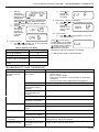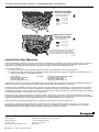
1
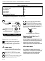
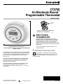
CT2700
An Electronic Round™
Programmable Thermostat
USER’S GUIDE
MERCURY
SWITCH
TYPICAL LOCATION OF A MERCURY
SWITCH IN A THERMOSTAT
M10614
RECYCLING
THERMOSTAT
If this thermostat is replacing a control that
contains mercury in a sealed tube, do not place
your old control in the trash. Contact your local
waste management authority for instructions
regarding recycling and the proper disposal of this
control, or of an old control containing mercury in a
sealed tube.
Programmable Heat and/or Cool
Low Voltage (20 to 30 Vac) Thermostat and Wallplate
Model CT2700
Congratulations on the purchase of your new thermostat!
Over 100 years of Honeywell engineering expertise went
into the making of this thermostat in an effort to provide
you with a more comfortable and convenient living
environment.
If you have questions, call Honeywell, Inc. at
1-800-468-1502.
1 PREPARE FOR INSTALLATION
Check Table 1 to make sure this thermostat is
compatible with your system. If not, return to the
retailer. For more information, call Honeywell, Inc. at
1-800-468-1502.
Your new thermostat will automatically control the temperature in your home, keeping you comfortable while
saving energy when programmed according to the
instructions in this manual.
Direct any questions concerning the application of this
thermostat to Honeywell Customer Assistance at
1-800-468-1502, Monday - Friday 7:00 a.m. - 5:30 p.m.,
Central time.
®U.S. Registered Trademark
Copyright © 1997 Honeywell Inc. •
• All Rights Reserved
X-XX UL
69-1085
CT2700 AN ELECTRONIC ROUND ™ PROGRAMMABLE THERMOSTAT
Table 1. Compatibility Chart
System Type
Compatible With CT2700
Yes a
Yes
Yesa,b
No
Yes b
Yes
Yes
Yes
No
No
Gas—Standing Pilot
Gas—Electronic Ignition
Gas-Fired Boilers
Gas—Millivolt
Oil-Fired Boilers
Oil-Fired Furnace
Electric Furnace
Electric Air Conditioning
Baseboard Electric (120/240 Line Volt)
Heat Pumps/Multistage Equipment
Not compatible with any 120/240 volt circuit.
Not compatible with 2-wire White-Rodgers no. 1361 zone valves.
aNot compatible with millivolt systems.
bCompatible with 2-wire Honeywell zone valves. Isolating relay required for 3-wire thermostats zone valves
Acquire tools and items as needed. See Fig. 1.
CROSS-RECESSED
SCREWDRIVER
Loosen screws holding thermostat to subbase,
wallplate, to wall and lift away.
Disconnect wires from old thermostat or subbase.
As you disconnect each wire, use masking tape to
label it with the old terminal designation. If there are only
two wires, they do not need labeling. Wrap wires around a
pencil to keep them from falling back into the wall as
shown in Fig. 2.
HAND OR POWER
DRILL WITH 3/16 INCH
DRILL BIT, IF NEEDED TO
DRILL HOLES IN WALL
WIRES THROUGH
WALL OPENING
WIRE CUTTER/STRIPPER OR SHARP
KNIFE, IF NEEDED TO STRIP WIRES
MASKING TAPE, IF
NEEDED TO LABEL WIRES
AS DISCONNECTED FROM
OLD THERMOSTAT
M5136
Fig. 2. Wrapping wires around pencil.
LEVEL, IF NEEDED TO LEVEL
THERMOSTAT FOR APPEARANCE
M878B
Replacing Clock With C or C1
Clock Terminals
Fig. 1. Required installation tools/supplies.
If you are replacing a Honeywell Chronotherm® Thermostat, you may find one or two wires that go to the C or C1
clock terminals on the Chronotherm® Thermostat wiring
wallplate. Do not allow them to touch, or you can damage
your transformer. Disconnect the wires and wrap them
separately using electrical tape; do not wrap them
together. Place the wires to avoid interfering with the new
thermostat operation. Record the colors and terminal
designation labels of the remaining wires.
2 REMOVE OLD THERMOSTAT
Test to make certain that your heating and air
conditioning systems (where applicable) are working
properly. If either does not work, contact your local
heating/air conditioning dealer. To avoid compressor
damage, do not operate the cooling system when outdoor
temperature is below 50°F (10°C).
Six or More Wires
CAUTION
Be careful when handling wires during
installation.
Damage to heating/cooling system possible.
Disconnect power at furnace or at main breaker/
fuse box before starting operation.
If there are six or more wires connected to the thermostat
(excluding clock wires attached to terminals), you probably
have a variation of a multistage heat pump or other
multistage system. The thermostat is not compatible with
such systems so return the product to your retailer. If you
would like information about which programmable
thermostats work with your system, call Honeywell
Customer Assistance Center at 1-800-468-1502.
Carefully unpack your new thermostat, wallplate,
and decorator cover plate; save package of screws,
instructions and receipt.
Remove the cover from the old thermostat. If it does
not snap off when pulled firmly from the bottom,
check for a screw used to lock on the cover.
69-1085
2
CT2700 AN ELECTRONIC ROUND ™ PROGRAMMABLE THERMOSTAT
4 WIRE WALLPLATE TERMINALS
Three Thermostat Wires
If you have three wires for heating only and can operate
the fan using the FAN ON switch, this thermostat works
with your system. However, some hot water (zoned)
heating systems have three thermostat wires. The
thermostat will work only if you install an isolating relay on
these systems. For details, call Honeywell Customer
Assistance Center at 1-800-468-1502.
The CT2700 Thermostat is powered through the heating/
cooling system and is adaptable to most 4-wire, 18 to 30
Vac heating-cooling systems. Refer to Figs. 4 through 6 for
some typical system wiring diagrams.
T8700
R
G
COOLING
CONTACTOR
Y
3 MOUNT WALLPLATE
W
IMPORTANT
Level for appearance only. The thermostat
functions normally even when not mounted level.
FAN
RELAY
HEATING
PRIMARY
CONTROL
1
L1
(HOT)
24V
L2
Position the decorator cover plate and wallplate on
the wall. Level the wallplate for appearance if
desired. Use a pencil to mark the two mounting holes that
best fit the application. See Fig. 3.
POWER SUPPLY. PROVIDE DISCONNECT MEANS AND
OVERLOAD PROTECTION AS REQUIRED.
M12525
1
Fig. 4. CT2700 wiring diagram,
4-wire heat/cool system.
WALL
T8700
R
G
DECORATOR
COVER PLATE
PLASTIC SCREW
ANCHOR (2)
Y
W
HEATING
RELAY AND
FAN COIL
1
WALLPLATE
C
24V
L
OO
O FF
HEAT
F
A
N
POWER SUPPLY. PROVIDE DISCONNECT MEANS
AND OVERLOAD PROTECTION AS REQUIRED.
N
O
1
TO
AU
M12543
Fig. 5. CT2700 wiring diagram,
2-wire, heat-only system.
T8700
R
M12532
G
Fig. 3. Mounting decorator cover plate and
wallplate to wall.
Y
FAN
COIL
W
Remove the decorator cover plate and wallplate
from the wall, and drill two 3/16-inch holes in the wall
(if drywall). For firmer wall material such as plaster or
wood, drill 7/32-inch holes. Gently tap provided anchors
into the drilled holes until flush with the wall.
COOLING
CONTACTOR
COIL
1
L1
(HOT)
24V
L2
1
Reposition the decorator cover plate and wallplate,
pulling wires through the wiring opening. Loosely
insert the mounting screws into the holes.
POWER SUPPLY. PROVIDE DISCONNECT MEANS
AND OVERLOAD PROTECTION AS REQUIRED.
M12544
Fig. 6. CT2700 wiring diagram,
3-wire, cool-only system.
Level for appearance only; the thermostat functions
properly even when not level. Tighten the mounting
screws.
IMPORTANT
Use 18-gauge maximum wire to wire the
thermostat.
3
69-1085
CT2700 AN ELECTRONIC ROUND ™ PROGRAMMABLE THERMOSTAT
5 ADJUST FAN OPERATION SWITCH
All wiring must comply with local electrical codes and
ordinances. If unsure about household wiring procedures,
call your local heating and air conditioning contractor.
The thermostat fan operation switch, labeled fuel switch in
Fig. 9, is set at the factory in the F (gas/oil fuel) position.
This is the correct setting for most systems. If this system
is an electric heat system, set the switch to the E (electric)
position. The E setting allows the fan to turn on immediately with the heating or cooling equipment in a system
where the G terminal is connected.
Refer to the masking tape labels you placed on wires
when you removed your old thermostat.
Match the letter of your old thermostat wire with the
terminal of the corresponding letter on your new
thermostat. Refer to Fig. 7.
ROUTE WIRING AS
SHOWN THROUGH
ENTRANCE
HOLE
FUEL SWITCH
ALTERNATE MOUNTING
SCREW HOLE
AT
HE
FA
N
ON
MOUNTING
SCREW
HOLE
F
E
TO
AU
CO
OL
FF
O
R
G
Y
W
M12531
ALTERNATE
MOUNTING
SCREW HOLE
MOUNTING
SCREW HOLE
WIRING ENTRANCE HOLE
Fig. 9. Fuel switch, rear view of thermostat.
M12529
6 MOUNT THERMOSTAT TO
Fig. 7. CT2700 wallplate wiring connections.
WALLPLATE
NOTE: To ensure proper mounting of the thermostat,
restrict all wiring to the left side of the terminals.
Align the tab and connector pins at the top of the
thermostat with the wallplate. See Fig. 10.
HE
O
AT
FF
FA
N
ON
CO
OL
DASHED LINES
INDICATE TABS
ON BACK OF
THERMOSTAT
TO
AU
Loosen the terminal screws and slip each wire
beneath its matching terminal. The shape of the
terminals permit insertion of straight or wraparound
connections. See Fig. 8. Tighten the terminals.
HE
Set
O
AT
FA
N
FF
ON
TO
AU
CO
OL
FOR WRAPAROUND, STRIP
7/16 INCHES (11 mm)
A ALIGN TABS/PINS AT TOP
OF THERMOSTAT WITH
WALLPLATE CONNECTOR.
FOR STRAIGHT INSERTION,
STRIP 5/16 INCHES (8 mm)
Set
M12537
Fig. 8. CT2700 methods for wiring connection.
B
Plug the hole in the wall with insulation to help
prevent drafts from adversely affecting thermostat
operation.
69-1085
M12530
PRESS THERMOSTAT CASE
STRAIGHT ON TO LATCH.
Fig. 10. Mounting thermostat to wallplate.
4
CT2700 AN ELECTRONIC ROUND ™ PROGRAMMABLE THERMOSTAT
Press the thermostat straight on to the wallplate to
latch.
3. Set WAKE
SET
Temperature
a. Press
.
b. Press
or
to set desired
WAKE temperature.
NOTE: To remove the thermostat from the wallplate,
grasp the thermostat on both sides and pull the
thermostat straight out.
4. Set SLEEP Time
a. Press
.
b. Press
or
to set desired
SLEEP time.
Restore power to the heating/cooling system.
7 PROGRAM YOUR THERMOSTAT
The thermostat is preprogrammed for your convenience
with the following time and temperature settings,
see Table 2.
Start
Time
Heating
Setpoint
WAKE
6:00 AM
70°F (21°C)
SLEEP
10:00 PM 62°F (16.5°C)
Cooling
Setpoint
82°F (28°C)
SLEEP is the time period you can set for an energysavings temperature while you are sleeping.
NOTE: The heating and cooling program times are the
same. Changing your cooling WAKE time also
changes your heating WAKE time.
PM
8 OPERATE YOUR THERMOSTAT
The following sequence uses the heating program as an
example; the System switch is in the HEAT position. To
change to the cooling program, move the System switch to
the COOL position and enter the cooling temperature
settings.
Display Temperature Setting
a. Press
or
once
SET
to display present
AM
temperature setting.
After approximately
five seconds, the
thermostat displays the current time and room
temperature.
NOTE: To exit the sequence at any time, press
until End is displayed.
Temporary Change
PM
a. Press
or
until
the desired temperature is displayed.
If you wish to change the preprogrammed time/ temperature settings, follow steps 2 through 6. If not, press the
key until End is displayed or the thermostat will
automatically return to normal operational mode within five
minutes.
2. Set WAKE Time
a. Press
.
b. Press
or
to set desired
WAKE time.
PM
6. Run Program
Press
. End is
displayed for five
seconds indicating the
end of programming.
The thermostat then
displays the current
time and room
temperature.
78°F (25.5°C)
WAKE is the time period you want the house at a comfortable temperature during the day.
1. Set Current Time
a. Press
.
b. Press
or
to set current
time.
PM
5. Set SLEEP
SET
Temperature
a. Press
.
b. Press
or
to set desired
SLEEP temperature.
Table 2. Preprogrammed Time/Temperature Settings.
Period
AM
b. TEMPORARY is
displayed.
The TEMPORARY
change is in effect
until the next program
period.
AM
SET
AM
TEMPORARY
AM
NOTE: To cancel your TEMPORARY change, press
until End is displayed.
5
69-1085
CT2700 AN ELECTRONIC ROUND ™ PROGRAMMABLE THERMOSTAT
10 CHECK OPERATION AFTER
Hold Function
INSTALLATION/PROGRAMMING
To hold the thermostat at one temperature indefinitely,
program both WAKE and SLEEP to the same
temperature.
Heating System
Slide the System switch to HEAT and the Fan switch
to AUTO.
9 SET FAN AND SYSTEM SWITCHES
Press and hold the
key to raise the temperature
several degrees above the room temperature to
start the heating equipment. When using the
thermostat with the fuel switch set to the E position
for electric heat, the fan starts immediately.
Manually control fan and system settings using the
switches located at the top of the thermostat case. See
Fig. 11 for switch locations.
TEMPERATURE DISPLAY
SYSTEM SWITCH
AT
HE
FA
N
Press the
key to lower the temperature setting
below the room temperature. The heating equipment
should stop.
ON
Cooling System
TO
AU
CO
OL
FF
O
FAN SWITCH
CAUTION
Operating at too low of an outdoor temperature
may cause compressor damage
Damage to compressor possible.
Do not operate cooling system if outdoor temperature is below 50°F (10°C). Refer to manufacturer
recommendations.
PM
Set
DECREASE
SETTING
IMPORTANT
Temporary protection delay protects compressor;
the thermostat allows the compressor to remain
off for five minutes before restarting.
INCREASE
SETTING
M12523
Slide the System switch to COOL and the Fan
switch to AUTO.
Fig. 11. CT2700 time/temperature display and
system/fan switches.
Press the
key to lower the temperature setting
several degrees below the room temperature to start
the cooling equipment.
Fan Switch
Press the
key to raise the temperature setting
above the room temperature. The cooling equipment
should shut down.
The FAN switch settings are:
ON: The fan runs continuously. Use for improved air
circulation.
AUTO: Normal setting for most homes. In cooling,
the fan starts and stops with the cooling equipment. In heating, the fan is controlled directly by
the heating equipment and starts a few minutes
after the heating equipment turns on (on most
systems). When the thermostat fuel switch is set
to the E position for electric heat, the fan starts
and stops with the heating equipment.
Fan
Slide the System switch to OFF and the Fan switch
to ON. The fan should run continuously.
CUSTOMIZE YOUR THERMOSTAT
The following instructions provide the information necessary to change the heating cycle rate to match your
heating equipment; choose Fahrenheit (°F) or Celsius
(°C); and 12- or 24-hour clock.
Slide the switch on the thermostat to the desired fan
setting.
System Switch
To exit at any time, press
The System switch settings control thermostat
operation as follows:
COOL: The thermostat controls the cooling system.
OFF: Both heating and cooling are off.
HEAT: The thermostat controls the heating system.
1. Enter Installer Setup
a. Slide System switch to OFF position.
b.
Slide the System switch on the thermostat to the
desired system setting.
69-1085
until End is displayed.
6
Use the
or
keys to set
the temperature
setpoint to 52°F
(11°C).
SET
AM
CT2700 AN ELECTRONIC ROUND ™ PROGRAMMABLE THERMOSTAT
c.
d.
After the
TEMPORARY
thermostat
AM
reverts back to
displaying room
temperature
(approximately five seconds), simultaneously
press
and
keys and hold for three
seconds. Release the keys after the display
changes.
Press
within
five seconds.
The display
changes to
show current
cycle rate
setting.
b.
3. Fahrenheit - Celsius Temperature
a. Use
or
to choose between °C and °F.
b. Press
to
display the
current 12- or
24-hour clock
setting.
4. Clock Format
a. Use
or
to choose either a 12- or 24hour clock format.
Press
once to exit the
Installer Setup. Upon exiting,
the temperature setting will
be at 52°F (11°C). Pressing
six times returns the
thermostat to the normal
operational mode. End appears in the display.
2. Cycles Per Hour
a. Use
or
to select 1, 3, 6, or 9 cycles per
hour (cph). Refer to Table 3.
Table 3. Heating Cycle Rates
System
Program Setting (cph)
Gas or oil forced air
6
Electric furnace
9
Hotwater baseboard, High
efficiency (90+) gas furnace
3
Steam, radiant floor heat,
gravity
1
Press
to
display the
current °F or
°C setting.
5. Slide system switch to desired position.
TROUBLESHOOT YOUR THERMOSTAT
Symptom
Heating/cooling
equipment will not
operate
Partial display
Possible Cause
Corrective Action
No AC power to
thermostat.
Check power to heating/cooling equipment:
— On/Off switch
— Fuse or circuit breaker
— Loose 24V connection: At thermostat; at furnace/air
conditioner
— Incorrect wiring: check appropriate wiring diagram.
Thermostat inoperative.
See checkout section.
System switch on
thermostat in wrong
position.
Reset System switch.
Thermostat minimum-off
times operating for
cooling.
Wait five minutes or follow steps in Checkout section.
Incorrect wiring.
Check wiring.
Heating/cooling
equipment inoperative.
Consult equipment manufacturer instructions.
Inoperative thermostat.
Replace thermostat.
Still in installer setup
mode.
See Installer Setup section for exit instructions.
No power to thermostat.
Check power to thermostat.
Thermostat mounted
incorrectly on wallplate.
See installation instructions for correct mounting.
Temperature display
is incorrect
Thermostat is configured
for °F or °C.
Reconfigure the display. See Installer Setup section for
instructions to change the display.
Cannot change
temperature setting
The upper or lower
temperature limits were
reached.
Check the temperature setpoints; temperature setting
range is 40°F (4°C) to 99°F (37°C).
No display
7
69-1085
CT2700 AN ELECTRONIC ROUND ™ PROGRAMMABLE THERMOSTAT
PERCENT OF HEATING
COSTS YOU CAN SAVE
SAVINGS FOR ONCE-A-DAY
10°F (5°C) DECREASE*
HEAT
6 TO
8%
9 TO 11%
12 TO 13%
14 TO 15%
16 TO 18%
PERCENT OF COOLING
COSTS YOU CAN SAVE
SAVINGS FOR ONCE-A-DAY
10°F (5°C) INCREASE*
COOL
7 TO
9%
10 TO 11%
12 TO 14%
14 TO 19%
* YOUR SAVINGS DEPENDS ON HOME SIZE AND
ACTUAL HEAT LOSS OR GAIN, GEOGRAPHIC
LOCATION, FREQUENCY OF TEMPERATURES
CHANGE, AND RANGE IN DEGREES OF CHANGE.
M12545
Limited One-Year Warranty
Honeywell warrants this product to be free from defects in the workmanship or materials, under normal use and service, for a period of
one (1) year from the date of the purchase by the consumer. if, at any time during the warranty period, the product is defective or
malfunctions, Honeywell shall repair or replace it (at Honeywell’s option) within a reasonable period of time.
If the product is defective,
(i) return it , with a bill of sale or other dated proof of purchase, to the retailer from which you purchased it, or
(ii) package it carefully, along with proof of purchase (including date of purchase) and a short description of the malfunction, and
mail it, postage prepaid, to the following address:
Honeywell, Inc.
Return Goods Department
1050 Berkshire Lane
Plymouth, MN 55441-4437
in Canada:
Honeywell, Limited/Honeywell Limitée
Product Services ON15-FFE
155 Gordon Baker Road
North York, Ontario M2H 3N7
This warranty does not cover removal of reinstallation costs. This warranty shall not apply if it is shown by Honeywell that the defect or
malfunction was caused by damage which occurred while the product was in the possession of a consumer.
Honeywell’s sole responsibility shall be to repair or replace the product within the terms stated above. Honeywell shall not be liable for
any loss or damage of any kind, including any incidental or consequential damages resulting, directly or indirectly, from any breach of
any warranty, expressed or implied, or any other failure of this product. Some states do not allow the exclusion or limitation or incidental
or consequential damages, so this limitation may not apply to you.
This warranty is the only expressed warranty Honeywell makes on this product. The duration of any implied warranties, including the
warranties of merchantability and fitness for a particular purpose is hereby limited to the one year duration of this warranty. Some states
do not allow limitations on how long an implied warranty lasts, so the above limitation may not apply to you.
This warranty gives you specific legal rights, and you may have other rights which vary from state to state.
If you have any questions concerning this warranty, please write our Customer Assistance Center, Honeywell, Inc., P.O. Box 524,
Minneapolis, MN 55440-0524, Monday - Friday, 7:00 a.m. to 5:30 p.m., Central time. In Canada, write Retail Products ON15-02H,
Honeywell Limited/Honeywell Limitée, 155 Gordon Baker Road, North York, Ontario M2H 3N7.
Home and Building Control
Honeywell Inc.
Honeywell Plaza
P.O. Box 524
Minneapolis, MN 55408-0524
69-1085 R.T. 8-97 Printed in U.S.A.
Home and Building Control
Honeywell Limited-Honeywell Limitée
155 Gordon Baker Road
North York, Ontario
M2H 3N7
8
Helping You Control Your World®