1
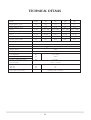
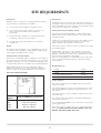
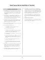
Central Heating Cooker
Natural Gas
Instructions for Use,
Installation and Servicing
For use in GB, IE (Great Britain and Eire)
This appliance has been certified for use in countries other than those stated. To install this appliance in these countries, it is essential to obtain the
translated instructions and in some cases the appliance will require modification. Contact Gazco for further information.
IMPORTANT
The front casing of this appliance will become hot whilst in operation, it is therefore recommended that a suitable guard should
be used for the protection of young children, the elderly or infirm.
Please read these Instructions carefully before installation or use.
Keep them in a safe place for future reference and when servicing the cooker.
The commissioning sheet found at the end of the Users Sections of these instructions should be completed by the Installer.
C603352 Issue 2 (Jan 2004)
HEALTH AND SAFETY
INFORMATION FOR THE INSTALLER AND SERVICE ENGINEERS
Under the Consumer Protection Act 1987 and the Health and Safety at Work Act 1974, it is a requirement to provide information on
substances hazardous to health (COSHH Regulations 1988).
The Company takes every reasonable care to ensure that these products are designed and constructed to meet these
general safety requirements, when properly used and installed.
To fulfil this requirement products are comprehensively tested and examined before despatch.
This appliance may contain some of the items below.
When working on the appliance it is the Users/Engineers responsibility to ensure that any necessary personal protective
clothing or equipment is worn appropriate to parts that could be considered as being hazardous to health and safety.
INSULATION AND SEALS
Glass Rope, Mineral Wool, Insulation Pads, Ceramic Fibre, Glass Insulation.
May be harmful if inhaled. May be irritating to the skin, eyes, nose or throat. When handling avoid inhalation
and contact with eyes. Use (disposable) gloves, face masks and eye protection.
After handling wash hands and other exposed parts. When disposing, reduce dust with water spray,
ensure parts are securely wrapped.
GLUES, SEALANTS & PAINT
Glues, Sealants and Paints are used in the product and present no known hazards when used in the manner
for which they are intended.
2
GENERAL SAFETY INSTRUCTIONS
Read and understand this booklet before operating and installing this appliance.
1
The person(s) who installs this appliance, commissions, services or carries out any remedial work, ie electrical fault finding must be
Corgi registered.
2
The cooker should not be altered in any shape or form.
3
Approved spare parts only may be used.
4
The cooker is designed to be operated by adults only. Children should not be allowed to play with or be near to the cooker, and
should be supervised at all times if in the vicinity of the cooker.
5
When in use, parts of the cooker become very hot (eg hot plates and ovens) and remain hot for a long period after use. You must
therefore take great care when using the cooker and the use of oven gloves is recommended when applicable.
6
In the interest of hygiene and safety the cooker should be kept clean at all times.
7
The Redfyre is designed for domestic cooking, hot water and central heating and must not be used for any other purpose.
8
Always switch off at the mains and allow to cool before cleaning and carrying out anymaintenance work.
9
Do not use unstable saucepans and always position handles away from the edge of the hot plate.
10
Do not place combustible materials onto the hot plate surfaces even when the cooker is off.
11
This appliance is heavy and care must be taken when installing.
12
DO NOT spray aerosols in the vicinity of this appliance while it is in operation.
13
DO NOT COVER THE OUTLET ON THE TOP REAR SPLASH BACK COVER
14
SERVICING. Your Redfyre cooker should be serviced every twelve months. It is impossible to service your cooker while it is hot,
therefore turn off your appliance 12 hours before a service is required.
15
These instructions explain the features of your new storage cooker, and how to achieve the best results, the cleaning, maintenance and
the installation and servicing. Please read the instructions carefully so that you can enjoy cooking and how to look after your cooker so
it gives you many years of service.
As with any heat storage cooker when first used odours are given off which are not harmful. However you should open windows or
doors to keep the room well ventilated until the odour disappears.
3
CONTENTS
Imortant Information
5
USER INSTRUCTIONS
6
Oven Cooking Guide
10
Care of the Cooker
12
Fault Finding Charts
13
After Sales Service Information
14
Technical Details
16
Site Requirements
17
INSTALLATION INSTRUCTIONS
19
Flue Systems
22
Water Systems
24
Electrical Supply
27
SERVICING INSTRUCTIONS
31
Replacement of Parts
31
Fault Finding Charts
36
Spare Parts List
40
4
IMPORTANT INFORMATION
Congratulations you are now the proud owner of the new Redfyre
Central Heating Cooker which is capable of providing full central
heating and domestic hot water. As manufacturers we are proud of
the features, and quality of construction of all our cookers.
Ventilation
Do not block the appliance lower door as the air for combustion is
taken through these slots. Do not shut off or block any additional
air vents fitted by your installer in any compartment or to the outside.
These instructions explain the features of your new cooker, how to
achieve the best results, the cleaning and maintenance. Please
read the instructions carefully so that you can enjoy cooking and
can look after your cooker so it gives you many years of service.
As with any heat storage cooker, when first used odours are given
off which are not harmful. However you should open windows or
doors to keep the room well ventilated until the odour disappears.
Do not adjust any sealed components, as this will affect the
performance of your appliance and your safety.
Spares Parts & Service
A 12 month warranty and a nationwide network of Service
Engineers cover all Redfyre products.
The use of a cooking appliance results in the production of heat
and moisture in the room in which it is installed. Ensure that the
kitchen is well ventilated: keep natural ventilation holes open or install
a mechanical ventilation device (mechanical extractor hood)
Prolonged intensive use of the appliance may call for additional
ventilation, for example opening of a window, or more effective
ventilation (see Air Supply & Ventilation Section for details)
All Redfyre products must be serviced at least annually by a
competent person using approved spare parts available from
Redfyre.
Frost Protection
If the boiler is to be out of use for a long period of time during
severe weather conditions, it is recommended that the whole
heating system be drained down to avoid the risk of freezing up.
Frequent draining, especially in hard water areas, should be
avoided as this may lead to scale build up inside the boiler.
The contents of these instructions are accurate at the date of
printing, however, because of Redfyre’s policy of continual
development, it may be superceded and should be disregarded if
specifications or appearance change. The statutory rights of the
customer are not affected.
For short periods of absence leave the boiler operating at a low
thermostat setting. If a frost thermostat is fitted, leave the boiler
with the thermostat turned to low and the time switch to off.
This appliance is designed for domestic use only. Use for any
other purpose could invalidate any warranty or liability claim.
The DATA BADGE is located on the burner access panel found
behind the bottom left hand door.
IMPORTANT CUSTOMER NOTICE
Cosmetic damage, stains and scratches
produced by cooking and cleaning are NOT
covered by the statutory guarantee. The user
MUST be aware of this before the cooker is
installed and commissioned.
Gas Leak Warning
If a gas leak exists or is suspected, turn the gas off at the incoming
mains adjacent to the meter and obtain help/advice from your gas
provider.
1.
2.
3.
4.
5.
6.
Do not operate any electrical appliance.
Do not operate any electrical switches.
Open all windows and doors.
Do not smoke.
Extinguish all naked lights.
Contact your gas provider immediately.
5
USERS INSTRUCTIONS
The Redfyre cooker has two large ovens. The main oven
works similar to a conventional oven which is controlled by
its own programmer and thermostat, this thermostat also
controls the rest of the appliance. This oven will reach a
roasting oven temperature in approximately 20 - 25 minutes
from cold and less if it has already been in use during the day.
2.2 This oven is ideal for long slow cooking and is ideal for
putting the roast to rest before carving, slow cooking
vegetables, meringues and milk puddings. As its size is
identical to the main oven there is plenty of room for
warming serving dishes or pre-warming cooking utensils
before use. When making bread, dough can be placed in
the oven to make it rise free from draughts. Spillages can be
wiped and surfaces wire brushed similar to the main oven to
keep them clean.
1. MAIN OVEN
3.HOTPLATES
1.1 The main oven is very spacious and will easily accommodate
the largest of roasting joints ie a 12kg (28lb) turkey. It is
constructed from 5mm mild steel plate and all joints are
welded to seal in natural juices and flavour when roasting as
well as minimising shrinkage. Any kind of food spillage in the
main oven will be automatically burnt off at high
temperature, all you have to do is brush it out with a wire
brush.
3.1 The hotplate is large enough to take up to seven various
sized saucepans, surely big enough for the largest meal. The
hotplate is graduated in temperature with the left side being
the hotter. With the hotplate being one piece pans can slide
from one side to another without the risk of damaging the
enamel surround. The insulated lids and decorative centre
cover conserves heat when not in use. However, one must
be careful when removing the decorative centre cover and a
oven glove must be used. When the cooker has been in use
the cover will be hot and may damage sensitive surfaces if
placed on them. Obviously the higher the oven temperature
setting the hotter the hotplates will become, it may only take
10 - 15 minutes from cold for the hotplate to be used. The
black enamel surround of the hotplate becomes warm when
in use and is ideal for keeping a coffee pot warm,
dissolving gelatine and melting butter.
1.2 The highly insulated door and high quality door seal closes
with a spring loaded action to ensure that there is minimal
heat loss with oven door closed.
1.3 There are four oven shelf positions within the oven which are
designed to take the oven grid shelves and roasting tins to give
the maximum area coverage. The top oven shelf position is
ideal for grilling and roasting.
1.4 A farmhouse breakfast can be produced by lightly greasing
the base of the roasting tin. Carefully crack some eggs and
place in one half of the tin, in the other half place slices of
bread. Using a grill rack over the eggs and bread lay bacon
and sausage, the fat will drip out during cooking onto the
eggs and bread to help flavour them. You can also add
tomatoes and mushrooms to the tin if you like. Cooking this
way helps keep the top of your cooker cleaner and make less
mess. Similarly fillets and fish give excellent results when
grilled using this method.
4. THE CONTROL PANEL
4.1 The control panel is located behind the top left hand door
and is self explanatory, it consists of :
4.2 One cooker programmer and two thermostat switches - one for
central heating and one for cooking.
1.5 The thickness and the construction of the oven walls enable
heat to be transferred all around the oven so excellent results
can be achieved by cooking on the base of the oven for
pastry dishes and quiches. Alternatively it can be used for
shallow frying,again containing splashes to the inside of your
oven which will burn off at high temperatures as previously.
explained.
4.3 The cooker thermostat has a neon indicator which goes off
when the main oven has reached its desired temperature.
The boiler thermostat has a neon indicator which goes off
when the boiler has reached its desired temperature.
4.4 There are two safety manual overheat thermostats, each have
a neon indicator, which when lit will require resetting. If the
overheat thermostat requires continual resetting you must
contact your distributor to check the appliance is operating
correctly, it may require a service.
2. LOWER OVEN
4.5 There are two reset burner buttons behind the lower left hand
door, one for the boiler and one for the cooker. These will
illuminate if the burner has gone to lock out, simply press the
button to try and refire the burner (make sure that the correct
thermostat is calling for heat). If the burner continues to go to
lock out, then you need to call your service company or
installer.
2.1 The lower oven is the same size as the main oven and
operates at a temperature of approximately 100° C lower
than the main oven, therefore if the main oven is operating
at a temperature of above 200° C the lower oven can only be
used as a warming oven.
4.6 There is one additional safety device reset button behind the
lower left hand door. The light will illuminate if there is a
problem with the flue system. It can be reset by pressing the
reset button. If this illuminates more than twice call a service
engineer to check the flue for blockages.
6
USERS INSTRUCTIONS
2
5. LIGHTING THE BURNERS
COOKER BURNER
5.1 The cooker burner is fully automatic and requires no manual
intervention to light. Ensure that the programmer is in the
ON mode, neon glowing, and turn the thermostat to the
desired temperature. The cooker light will illuminate and once
the desired temperature has been reached it will extinguish.
ON
OFF
AUTO
ALLDAY
+ 1 HOUR
ADVANCE
BOILER BURNER
SELECT
PROG
1 HR
5.2 The boiler burner is fully automatic in operation and requires
no manual intervention to light. Ensure that any external
controls are on and calling for heat and that the thermostat is
turned on to the desired temperature. The boiler light will
illuminate and once the desired temperature has been
reached it will extinguish.
ADV
Unit with programming cover removed
6. SWITCHING OFF
Factory programming.
6.3 The unit can provide up to 3 On/Offs each day.
In order to simplify programming a factory pre-set
programme is included. This can be easily altered to suit
household lifestyle and needs.
Please note the section on frost protection. (page 1)
6.1 For short periods: Turn all the external controls to off and
turn the boiler thermostat to ‘off’. Turn the cooker thermostat
to ‘off’ and switch the cooker programmer to off.
Event 1
Event 2
Event 3
6.2 For Long Periods: Turn all external and internal controls to
off, switch off the electrical supply to the unit.
ON = 06:30 AM
ON = 12:00 PM
ON = 05:00 PM
OFF = 08:30 AM
OFF = 02:00 PM
OFF = 10:30 PM
Setting the time of the day.
6.4 Remove the programmers button cover.
7. PROGRAMMER -COOKER
6.5 Press PROG to enter programming mode. The display will be
as in diagram 3 and the colon in the display will not flash.
6.1 In general the programmer is used either to turn ‘On’ of
‘Off’ the cooker manually or automatically.
3
Programmer Setting instructions
ON
OFF
AUTO
ALLDAY
+ 1 HOUR
ADVANCE
6.2 On initial power-up the unit should be re-set to wake up the
unit remove the programmers button cover, see figure 2. To
re-set the unit press and hold the four buttons shaded grey,
see diagram 1.
1
6.6 Press and release the + or - button to change the time in
one minute increments. Note: If the button is held down, the
time will change in increments of 10 minutes.
SELECT
PROG
1 HR
ADV
6.3 Figure 2 depicts how the display will look after being re-set.
7
USER INSTRUCTIONS
Battery back-up.
Setting event times
In the event of a power failure the time and programmed
events will be retained for up to 14 days, after which the unit
will go into sleep mode, and will need to be reprogrammed
when the power is restored (refer to Initial Power-Up at
beginning of instruction).
Step A
6.7 Press PROG to advance to the next step. The display will be
as in diagram 4.
4
8. CENTRAL HEATING
8.1 For heating or hot water (depending on how the appliance
has been installed), you simply have to turn the heating
thermostat to the desired temperature. If you have an external
programmer or other controls fitted you must ensure these are
calling for duty.
Step B
6.8 Press and release the+ or - buttons to change event 1 ON
time in increments of one minute.
Note: If buttons are held down, the time will change in
increments of 10 minutes.
1
Step C
6.9 Press PROG again to select event 1 OFF time. The display
will be as in diagram 5.
5
6.10 Repeat steps A, B and C above for event 2 ON/OFF times
and again for event 3 ON/OFF times before pressing PROG
again to return to RUN mode.
6.11 Having finished programming, replace the programming
button cover.
Use the Cooker SELECT button to select between:
ON
OFF
AUTO
ALL DAY
Run continuously
Off continuously
Follows programme
Turns on first programmed ON
event and off at end of last
programmed OFF event.
Use A D V or +1HR to override programmes.
ADV
Advances unit to
next event.
+1HR
Adds 1 hour onto
end of current
programme.
8
USER INSTRUCTIONS
9. BLOCKED FLUE
9.1 This is a blocked flue sensing device. This is an important
safety device to prevent the products of combustion entering
the room due to a flue problem. Under no circumstances
must this device be put out of operation whilst the cooker is
in use.
9.2 If either one or both burners are switched off by this device,
the red neon will illuminate. It will not be possible to relight
the appliance for approximately 30 minutes after which time
the reset button should be pressed.
9.3 In the event of repeated activation of the blocked flue device
the chimney / flue problem must be investigated and corrective
action taken immediately.
9.4 Access to the reset button is achieved by opening the control
lower left hand door and pressing the red reset button.
Approx Time
From Cold
Top Oven
Bottom Oven
Temperature
Hotplate
L/H side
R/H side
18 min
140° C
Warming
Boil
Simmer
20 min1
60° C
Warming
Boil
Simmer
22 min1
80°C
Warming
Boil
Boil
24 min
200° C
Simmer
Boil
Boil
26 min
220° C
Simmer
Boil
Boil
28 min
240° C
Simmer
Boil
Boil
9
OVEN COOKING GUIDE
1. MEAT
2. POULTRY
PLEASE NOTE - THESE TABLES SHOULD BE USED AS GUIDENCE
ONLY AS EACH COOKER AND ITS INSTALLATION WILL VARY
SLIGHTLY.
1.1 Poultry and Game are best cooked on a trivet in a roasting
tin so that the meat does not stew in it’s own juices.
Remember to calculate any stuffing into the cooking time. All
birds must be thoroughly thawed out before cooking
1.1 Meat cooked in a heat storage cooker has very little shrinkage
and rarely requires any additional fat for cooking. There are
two basic methods for roasting meat, to quick roast at setting
200°C for superior cuts, and for slower roast at setting 170°C
for coarser cuts, where muscle has been worked far more.
We would recommend searing or sealing an inferior cut at a
high temperature for approximately 20/30 minutes before
reducing the thermostat to the lower setting. Roast meat will
benefit if left to stand when cooked, it allows the juices to
settle and makes for easier carving. Transfer to the lower
oven for this rest period, it will leave the top oven free for
such items as roast potatoes or Yorkshire pudding.
Setting Shelf
Chicken
170°C
Turkey over 4.5kg - quick 170°C
3
30-35 min per 500g+30-35 min
- quick 200°C
3
20-25 min per 500g+20-25 min
Duck
170°C
3
30-35 min per 500g+30-35 min
Goose
170°C
3
35-40 min per 500g+35-40 min
3. CASSEROLES
1.3 The oven control settings and cooking times given below are
intended to be used as a guide only. Individual tastes may
require you to adjust the control setting either up or down or
to reposition the item being cooked.(If oven temperatures
seem to be abnormal to those stated then the oven thermostat
could be faulty and may require replacing.
Remember to sear or seal the meat over a high heat before adding
to the casserole, and to bring to boiling point any liquids if recipe
requires.
Setting
Beef with bone - slow 170°C
3
3
15-20 min per 500g+15-20 min
3
30-35 min per 500g+30-35 min
Pork or Veal
- quick 200°C
3
20-25 min per 500g+20-25 min
- slow 170°C
3
30-35 min per 500g+30-35 min
- quick 200°C
3
25-30 min per 500g+25-30 min
- slow 170°C
3
35-40 min per 500g+35-40 min
- quick 200°C
3
25-30 min per 500g+25-30 min
Shelf
140-150°C
Fish oven baked 180°C
20-25 min per 500g+ 20-25 min
- quick 200°C
Lamb
Top oven
Approx time
Beef boneless - slow 170°C
20-25 min per 500g+ 20-25 min
Turkey up to 4.5kg - slow 170°C 3 15-20 min per 500g+15-20 min
- quick 200°C 3 15-20 min per 500g+15-20 min
1.2 If the lower oven is not free, cover to keep warm. To
calculate cooking times always take into account the shape as
well as the weight. A small, narrow joint will cook quicker
than a solid, even shaped joint.
Setting Shelf
3
Approx time
Approx time
3
Hours according
to recipe
2
According to size, cut,
preparation, and recipe.
4. CAKES
Setting
NOTE : If stuffed and rolled add approximately 10 min per 500g.
All joints must be thoroughly thawed out before cooking.
10
Shelf
Approx time
Rich fruit cake
140-150°C
Victoria sandwich 180°C
4
3
Approx guide line 45 min
per 500g of mixture.
180-230 mm 200mm
(7-8”) tin, 2-3 hr.
Queens cakes
(2 trays)
180-190°C
2
3
15-25 min
Scones
200°C
2
10-15 min
OVEN COOKING GUIDE
5. PASTRIES
Setting
Shelf
Approx time
Shortcrust
220°C
4
According to recipe
Flaky
220°C
2
According to recipe
Rough puff
220°C
2
According to recipe
Puff pastry
220°C
2
According to recipe
NOTE: Pastry recipes may benefit from placing on the floor of the
oven for the last 10-15 min of cooking. Shelf positions are counted
from the top down 1,2,3, and 4. 500g is approximately 1lb 2oz.
USES FOR THE PROGRAMMER
If it is winter time, you can preset the programmer to your own
personal program allowing the cooker to switch on before you
return, when your lifestyle takes you away from home during the
day, or simply to switch on the cooker before you wake in the
morning to a warm kitchen and breakfast can be prepared quickly.
To switch Off if not required and on again before the family return
at the end of the day to cook the evening meal, and then off just
before you retire. Do not forget this appliance has loads of stored
heat, use it to save fuel accordingly.
COLD START COOKING
Choose food carefully when there is a time delay before cooking
commences. Ideally food should be taken from the refrigerator
and placed in the oven and cooked. Never place hot or warm
food from previous usage in the oven for a delayed cook time.
Remember there will be no one attending to the food during
cooking, so do not overfill dishes.
Remember that there are different heat zones in the oven and
place the food on the correct shelf position.
Perishable foods should be very fresh.
Protect food, wherever possible with a lid or
aluminium foil.
Important: Keep the delay cook time as short as possible, given the
right conditions of food, moisture and warmth bacteria will rapidly
multiply.
THE MAIN REASON FOR FOOD POISONING IS THE STORAGE
OF HIGH RISK FOOD AT ROOM TEMPERATURE.
11
CARE OF THE COOKER
IMPORTANT:
Never use caustic, citric, or abrasive cleaners as these will scratch or
damage the surface.
Always try to wipe up any spillages when they occur.
A more satisfactory result will be achieved if the cooker is cool
when cleaning.
Use hot soapy water and a cloth for the enamel, drying with a
soft dry cloth after to avoid streaking.
Top plate
Hot plate dome chrome
✓
✓
Oven
Oven door
Door Liner
Seal
Colour parts
Front
Sides
Doors
Chrome handles
Towel rail
Nylon brush
Cream cleaner VE Approved
✓
✓
✓
✓
Hot plates
Chrome Shelves
Wire brush
Hot water & soap
To clean the ovens simply wire brush any stubborn carbon stains
and vacuum away the deposits. Using a wire brush can scratch the
surface of the oven but this is not detrimental. The surfaces of the
oven are natural, therefore to prevent oxidation dry all surfaces
after cleaning.
✓
✓
✓
✓
✓
✓
✓
✓
✓
✓
✓
✓
12
USER COOKER FAULT FINDING
COOKER WILL NOT START
YES
IS THE COOKER PROGRAMMER
SWITCHED ON
(NOTE PROGRAMMER WILL
‘GO TO SLEEP’ IF POWER SUPPLY
HAS BEEN INTERRUPTED FOR MORE
THAN 14 DAYS - REFER TO
PROGRAMMER INSTRUCTIONS TO
WAKE UP THE PROGRAMMER
CHECK COOKER THERMOSTAT IS
SWITCHED ON AMBER NEON WILL BE
ILLUMINATED
YES
NO
IS THE COOKER RESET
NEON ILLUMINATED
YES
PRESS RESET BUTTON (DO NOT RESET MORE THAN TWICE
IF FAULT PERSISTS CALL YOUR
ENGINEER)
YES
IS THE COOKER BURNER RESET
BUTTON ILLUMINATED
YES
PRESS RESET BUTTON (DO NOT RESET MORE THAN
TWICE IF FAULT PERSISTS CALL YOUR
ENGINEER)
IF BOTH BOILER & COOKER RESET
BUTTONS ARE ILLUMINATED IT MAY
BE THAT YOU HAVE
RUN OUT OF OIL
13
NO
CHECK THE FUSE IN
COOKER &
BOILER MAINS SUPPLY
HAS NOT BLOWN
YES
REPLACE FUSE
IF FUSE BLOWS AGAIN
CALL YOUR ENGINEER
USER BOILER FAULT FINDING
BOILER WILL NOT WORK
YES
IS YOUR EXTERNAL PROGRAMMER
CALLING FOR HEAT
NO
SET EXTERNAL
PROGRAMMER
YES
YES
YES
IS THE BOILER HIGH LIMIT
RESET NEON ILLUMINATED
ON THE CONTROL PANEL
NO
IS THE BOILER BURNER RESET
BUTTON ILLUMINATED
NO
IS THE COOKER TEMPERATURE
NEON ILLUMINATED WHEN THE
COOKER THERMOSTAT IS
TURNED TO MAXIMUM
NO
CHECK THE FUSE IN
COOKER BOILER MAINS SUPPLY
PRESS RESET BUTTON (DO NOT RESET MORE THAN
TWICE IF FAULT PERSISTS CALL YOUR
ENGINEER)
IF BOTH BOILER & COOKER RESET
BUTTONS ARE ILLUMINATED IT MAY
BE THAT YOU HAVE
RUN OUT OF OIL
14
REPLACE FUSE
YES
IF FUSE BLOWS AGAIN
CALL YOUR ENGINEER
REDFYRE
CUSTOMER AFTER SALES SERVICE INFORMATION
A step by step guide to reporting a fault with your appliance
The Enamelled Parts on your cooker
A qualified field SERVICE ENGINEER is available to attend a
breakdown or manufacturing fault occurring whilst the appliance is
under guarantee.
Every enamelled part on your cooker is unique and has its own
individual characteristics which do not impair its quality of life
expectancy in any way. Enamelling emphasises the unique quality
and means that every cooker has its own distinguishing marks and
features. Coloured parts may differ in shading. It is extremely
important and to your own advantage and safety that your cooker is
properly installed and commissioned to the instructions and serviced
at the recommended intervals, failure to comply may invalidate your
warranty.
•
•
•
•
•
A charge will be made where:
Our Field Service Engineer finds no fault with
the appliance
or
The cause of a breakdown is due to other
parts of the plumbing/heating system (including oil line/lack of oil),
or with equipment not supplied by Redfyre.
or
Where the appliance falls outside the guarantee
period (see terms and conditions enclosed).
or
The appliance has not been correctly installed,
commissioned or serviced as recommended
(see commissioning, installation and servicing instructions)
or
The breakdown occurs immediately following an annual
service visit. In this instance you appointed Service Agent
must check all his work PRIOR to requesting Redfyre
to attend.
NOTE: Burner nozzles are currently guaranteed
until the first service.
Over 50% of all service calls made are
found to have no appliance fault.
What to do in the event of an appliance
fault or breakdown:
Step 1:
Always contact your installer or
commissioning engineer in the first
instance, who must thoroughly check all
his work PRIOR to requesting a service
visit from Redfyre.
Step 2:
If your appliance has developed an
in-guarantee fault your installer should
contact Redfyre Service Centre
for assistance.
What happens if my installer/engineer is unavailable?
Step 3:
Contact Redfyre Direct. We will provide you with the
name and telephone number of our Service Agent.
However,a charge may apply if the fault is not covered by
the appliance guarantee (payment will be requested on
site by our independent Service Agent).
PLEASE NOTE:
Unauthorised invoices for attendance and repair work
carried out on this appliance by any third party will not
be accepted by Redfyre.
15
TECHNICAL DETAILS
Model
Cooker
60
80
100
120
Rated input kw (gross)
17.6
22.2
29.7
37.3
45.5
Rated output kw (gross)
-
17.6
23.4
29.3
35.2
Cooker
Boiler - 60k
Boiler - 80k
Boiler - 100k
Boiler - 120k
1.68
2.11
2.84
3.56
4.34
Co2 %
8.5-9.0
7.0-8.0
8.0-8.5
8.5-9.0
8.5-9.0
Starting current - Amp
0.422
0.422
0.8
0.8
0.83
Running current - Amp
0.33
0.33
0.48
0.48
0.74
Burner
Gas Volume m 3/jr
Electrical power consumption
230v 50 Hz 95 watts
Gas Type
Natural Gas 20mbar G20
Gas Cat
I2H for use in GB, IE (Great Britain and Eire)
Weight - dry kg
512kg
Water content - Litre
38
Flow and Return
NA
2 x 11/4” BSP
Max Operating Pressure (PMS)
NA
3.0 bar
Operating Temparature Range
Conventional Flue
Operating Range
Water side resistance - mbar
10°C diff
20°C diff
NA
60 - 80°C
0.05 +/- 0.02” WG
12.45 +/- 4.98 Pa
NA
NA
26
8.3
Flue sockets - Dia. 145mm
Inside Flue Dia. 5” (125mm)
16
SITE REQUIREMENTS
Sound Levels
Extractor Fan
Whilst the level of sound is low it is important that the following
aspects should be considered before installation:
If the kitchen has an extractor fan, the combustion performance of
the appliance must not be affected when the fan is running and all
doors and windows are closed. A spillage check should be carried
out to prove that combustion is satisfactory.
(a)
The Flue pipe from the appliance should be cast iron
(b) Some people are particularly sensitive to even low noise
levels so this aspect should be discussed with the
householder.
(c)
Heating and Domestic Hot Water Systems
The heating system should be installed in accordance with current
HVCA Codes of Practice and BS 5449 Part 1 ‘Forced Circulation
Hot Water Systems’.
Small rooms tend to amplify noise, particularly if the wall
construction is hollow or the surface tiled.
Fit drain-off cock in the lowest part of the system. Where a boiler
is also used for providing domestic hot water, a double feed
indirect cylinder to BS 1566 Part 1 must be used.
(d) A chimney passing through a bedroom can sometimes
transmit noise.
Hearth
Flush out the system to remove any swarf or residues before fitting
the circulating pump.
The appliance must be fitted on a non-combustible base. Also the
floor must be level and capable of supporting the installed weight
of the appliance including its water content.
PLEASE NOTE: If the boiler is to be installed on a gravity type
system, care must be taken, i.e. due to the high efficiency of the
appliance consideration should be given to gravitational flows with
view to system contamination and operation.
Failure to comply with these recommendations may result in there
being a temperature build-up within the boiler/system causing
noisy operation.
Combustion Air (Conventional Flue)
The provision of an adequate supply of combustion air is essential for
the efficient and safe operation of the appliance. The air opening
should be positioned so as to cause the least possible draught to the
occupants and located so it is not liable to be accidentally blocked.
Overall dimensions
British Standard Code of Practice BS 5440 Part 2 requires a
permanent air inlet opening of 5cm2 per kW above 7kW (gross)
input. See below for the required ventilation for each model.
AIR SUPPLY AND VENTILATION
Height
917mm
Width
980mm
Depth (including towel rail)
795mm
Towl Rail
80mm
Cooker clearances
The cooker is designed to fit in a 1000mm space with a 10mm
clearance each side.
IN ROOM
If the right hand side of the cooker is to be positioned next to a wall,
then an extra 100mm is required at the right hand side for over
shelf removal.
Redfyre
Model
60
80
100
120
A clearance above the cooker of 550mm is required for the raising
of the dome lids.
Minimum FREE Area opening ‘A’
If a cooker hood it to be fitted then it should be installed to the
manufacturers instructions.
166 cm2 (15 in2)
198 cm2 (19.5 in2)
230 cm2 (24.5 in2)
262 cm2 (30 in2)
We recommend that 1000mm is left in front of the cooker to aid
cooking and servicing.
Where the cooker is to stand in a recess or against a wall which is
to be tiled UNDER NO CIRCUMSTANCES SHOULD THE TILES
OVERLAP THE BLACK ENAMEL TOP PLATE.
17
SITE REQUIREMENTS
FLOW and RETURN
tappings
114” BSP
125
1440
clearance,
(Min.)
970
915
604
Gas
158
70
Electric
126
167
206
51
87
985
CENTRAL HEATING COOKER DIMENSIONS
18
INSTALLATION INSTRUCTIONS
1.8 The installation of this central heating cooker MUST be
carried out by a competent person in accordance with the
relevant requirements of the current issue of the Gas Safety
(Installation and Use) Regulations, the Building Regulations,
the IEE Wiring Regulations, the Building Standards (Scotland)
Regulations (applicable in Scotland), Local Water Company
Byelaws, Health and Safety Document No 635.
1. GENERAL DESCRIPTION
1.1 The Redfyre range of Central Heating cookers is a range of
floor mounted storage central heating cookers with a fixed
rate cooker burner and the option of four fixed rate central
heating outputs depending on heating load. 60, 80, 100 x
12,000 BTU.
Detailed recommendations are contained in the current
issues of the following British Standards BS 5440 Pts 1 & 2,
BS 5449, BS 5546, BS 6700, BS 6798, BS 6891 and BS
7593.
1.2 The cooker has two independent matched premix gas
burners which are exceptiantly quiet in operation. One heats
the cooker and the other the central heating and are
controlled via thermostats with the cooker being controlled
bu an electronic programmer within the unit
1.9 Health and Safety at Work Act
The installer should be aware of his responsibilities under the
Act and provide, where necessary, appropriate protection for
persons carrying out the installation.
1.3 The boiler side of the cooker has been designed for use on
open vent or sealed systems. If it is to be used on a sealed
water system up to a maximum working pressure of 3bar,
additional safety devices will be required.
1.4 This cooker is suitable for use on natural gas only and must be
connected to a conventional flue.
1.5 Incorporated with the appliance are:a)
User adjustable controls for cooking oven and
central heating water temperature.
b) Burner running indicator neons
c)
Overheat thermostats (with neon indicators) on both the
cooker and boiler, with an additional pump over run
thermostat on the central heating circuit.
d) An integral electronic programmer to control the cooker
on and off times.
e)
A boiling spot and simmer spot in addition to a top oven
(with thermostat control) and a separate lower oven
which operates at approximately 100° C lower than the
top oven
f)
A blocked flue thermostat which prevents the unit
operating if a blocked flue occurs.
g)
Two efficient and quiet premix gas burners with fully
automatic ignition provide outputs with very Low NoX
values.
1.6 All servicing can be carried out from the front and top of the
appliance, thus allowing the cooker to be fitted between
kitchen units. The front mounted flue-cover permits easy
access for the removal of the flue baffles and cleaning of
heating surfaces.
1.7 This appliance has been designed to conform to European
Directive/Standards BED, LVD, EN, EMC and GAD.
19
INSTALLATION
3. TYPES OF CHIMNEY AND FLUE SYSTEMS
1. GAS SUPPLY
3.1 There are four basic chimney/vent systems that can be used
with gas fired appliances.
1.1 The supply pipe from the cooker is 3/4” BSP threaded male.
An isolating gas valve must be fitted adjacent to the cooker and
the gas installation pipe work must be installed, inspected,
tested for soundness and purged in accordance with BS 6891
Nominal inlet gas pressure
Maximum gas pressure
Minimum gas pressure
with both burners running
These are:Twin Wall Gas Vent.
20mbar
25 mbar
3.2 A metal twin wall flue system incorporating an air gap of
between 6 mm and 20 mm constructed in either all
aluminium for external use or aluminium inner and
galvanised or stainless steel outer skin recommended for
internal use only. Such products shall be certified to BS 715.
17 mbar
2. FLUE & CHIMNEY REQUIREMENTS
Stainless Steel Lined Prefabricated Chimneys.
2.1 To evacuate the products of combustion safely and
thoroughly, the cooker must have an efficient flue system.
Reference should also be made to BS 5440 Part 1 & 2 if
further information is required on conventional chimneys.
3.3 These chimney systems consist of two skins of stainless steel
or a combination of stainless steel and galvanised steel
incorporating high quality insulating materials. Depending upon
the materials of combustion, these products can be used internally
and externally. Such products shall be certified to BS 4543.
2.2 This unit is designed to work on a conventional flue system
with a draught of 0.05” +/- 0.02” W.G (12.45 +/- 4.98 Pa or
0.124 +/- 0.498 mbar).
Ceramic or Concrete Lined Prefabricated Chimney.
3.4 Similarly, constructed to the previous category except that
the inner liner is fabricated with either lightweight fireproof
concrete or ceramic material. These products shall be
certified by the British Board Agreement.
2.3 The chimney should rise as vertically as possible and terminate
at a point not subject to down draughts or wind eddies.
2.4 Brick and masonry chimneys must be lined with a moisture
and acid resistant liner of the same diameter as the boiler
flue outlet.
Concrete Block/Masonry Chimneys.
3.5 These can be divided into three different categories:-
2.5 A factory made insulated chimney complying with BS 4543
Part 3 may be considered as an alternative to a structural
chimney both for new and existing buildings.
(i) Conventional brick or masonry construction with either
clay to BS 1181 or refractory concrete flue liner manufactured
from a kiln burnt aggregate and high alumina cement.
2.6 The in-built flue gas resistance of the appliance is such that it
allows the boiler to operate reliably over the wide range of
chimney draughts encountered from typical domestic
chimneys. The use of a flexible stainless steel liner is a convenient
method of lining an existing chimney and this should be back
filled with ‘vermiculite’ or similar insulating material to retain
heat. A flexible liner should also be used in chimneys fitted
with large diameter clay liners to reduce the flue bore and
improve the thermal insulation.
(ii) Prefabricated chimney block systems
(iii) Gas Flue blocks.
3.6 Category (i) is the conventional chimney and in the majority
of installations where used with a gas appliance it will be
necessary to utilise a stainless steel flexible liner. The second
category (ii), prefabricated block chimney systems are designed to
accommodate quite a range of heating appliances, gas
appliances included. In some cases they may need to be
lined with a flexible liner. The appliance manufacturer and
chimney manufacturer should be consulted for guidance.
The final category (iii), gas flue blocks consists of a narrow
rectangular flue way within a building block normally used as
part of the internal or external construction of the house.The
flue way is usually very narrow, and the systems are often
linked with twin wall gas vent to which they are “adapted” in
the roof space, after which the gas vent completes the chimney
run through termination. Such systems should be carefully
inspected for soundness before being used. If they are
incorrectly constructed they can contribute to operational
difficulties and in particular condensation within the chimney
system as a whole. If any doubts should arise as to the
condition of such chimney systems they should be carefully
checked and possibly replaced with a new flue system.
2.7 The use of a draught stabiliser should not be necessary nor it
desirable since it allows flue noises to be emitted into the
room.
Notes:
1. In view of the appliances high terminal efficiency it is
important that a liner is fitted, otherwise condensation
problems could result.
2.Before fitting a liner, the chimneymust be thoroughly
cleaned free from all traces of soot and scale.
20
INSTALLATION
Flue Pipes.
3.7 These should only be used to connect a gas burning appliance to
one of the types of chimney previously mentioned. Any flue
type serving a gas appliance must be kept clear of any
combustible materials including any materials likely to be
located near the installation by the householder. The
minimum air gap clearance that must be maintained is 25
mm (1'').
Rain Cap
(Approved for
gas use)
Cement Mortar
Flue pipes may be constructed from the following materials.
Plate Clamp
MIN EFFECTIVE HEIGHT=3M
3.8 Sheet metal as described in BS 715 stainless steel flue pipe,
cast iron flue pipe as described in BS 41, any flue pipe
material described in the Building Regulations relating to flue
pipes suitable for solid fuel and oil burning appliances. All
flue pipes should be constructed such that any condensation
is retained by the flue pipe system. Systems with spigot and
socket joints must be fitted with the sockets uppermost.
Back fill with Vermiculite
Insulation or similar
Brick Chimney
Bends must be no less than 135°
Vitreous Enamelled Steel or
Stainless Steel with Cleaning
Cover
Stainless Steel
Flexible Flue
Liner
Seal Liner
into Flue Socket
with Fire Cement
4. LINING OF EXISTING CHIMNEYS
4.1 Before using any existing chimney or refitting a gas appliance,
it is vital to check that the chimney is safe. Oversized,
leaking or rough chimneys can be inefficient and dangerous.
MIN RISE
BEFORE BEND
=600MM
4.2 There are two basic existing types of chimney re-lining product
suitable for use with gas appliances. It is most important that
the chimney is swept and thoroughly cleaned before
installing a liner so as to remove previous combustion
deposits, which have the potential to damage the liner.
COVENTIONAL BRICK CHIMNEY WITH LINER
Flexible Stainless Steel.
4.3 Recommended where any existing chimney is to be used for
a gas-fired appliance. Flexible stainless steel liners must be
certified to BS 715. When replacing an existing appliance
connected to a chimney lined with a metallic liner, the liner
should be replaced.
Rigid Stainless Steel Flue Pipe
4.4 Type 316 or 304 stainless steel, not less than 0.55 mm thick.
21
FLUE SYSTEMS
The following drawing shows the general high and low
pressure areas on buildings.
5. WIND EFFECTS ON BUILDINGS
Flues should not be terminated in a high pressure area.
ROOF PITCH OVER 30°
ROOF PITCH OVER 30°
FLAT ROOF
WIND
HIGH
LOW
HIGH
LOW
HIGH
LOW
6.10 Ensure that the chimney is installed and located in
accordance with building regulations and Building regulations
and British standards, particularly the distances from
combustible materials are required.
6. IMPORTANT NOTES
Do’s
6.1 Ensure that when an appliance is fitted to any chimney
system, that it is inspected and tested for soundness so that
any defects are rectified or a new flue system provided if the
soundness is in doubt.
6.11 Remind the householder that a chimney and an appliance
must breath, which is why a permanent supply of combustion
air must be provided and kept clear of obstructions.
6.12 Advise the householder to have the gas appliance regularly
and expertly serviced.
6.2 Ensure that the flue system is always installed and supported
strictly in accordance with the manufacturers instructions.
6.13 Ensure that if a gas flue block or mixed system consisting of
gas flue blocks and prefabricated gas vent is constructed to
avoid constructional faults.
6.3 Ensure that all joints are properly, securely and efficiently
made in accordance with the manufacturers instructions.
6.4 Ensure that the flue pipe connections from the appliance rise
vertically for at least 600 mm (24'')before any change of
direction is contemplated. The reason for this is that the
initial draught is crucial nearer the appliance because of the
higher flue gas temperature. Any horizontal or angled runs at
the bottom of the flue will create severe restriction to the gas
movement and affect appliance operation.
6.14 Ensure that the flue is terminated in accordance with
Building regulations.
6.5 Try to construct the chimney vertically all the way to the
terminal.
6.16 Use non insulated flue systems externally.
Don'ts
6.15 Use single walled galvanised ducting as a flue system for any
domestic gas installation.
6.17 Allow clothes, furnishings or any combustible material to
come into contact with any flue pipe.
6.6 Ensure that no part of the flue is installed at an angle more
than 45°/135°
6.18 Use bends if they can be avoided.
6.7 Ensure that the flue diameter is not less than the
appliance outlet.
6.19 Run horizontal flue anywhere in the system.
6.20 Position the chimney externally if it can be avoided.
6.8 Ensure that the effective vertical height of any chimney with
bends is at least twice that of the horizontal distance between
appliance and terminal.
6.21 Be tempted to use inferior materials for the flue system; they
may only last a short time and replacement would be costly.
6.9 Try to position the chimney inside the building to avoid
excessive cooling and risk of condensation.
22
FLUE TERMINATION
IRRESPECTIVE OF THE TYPES OF CHIMNEY
SYSTEM, A BRITISH GAS APPROVED TERMINAL
MUST BE USED
Recommended flue positions
for some roof conditions
23
WATER SYSTEMS
1. GENERAL
4. EXPANSION VESSEL REQUIREMENTS
1.1 The appliance is suitable for fully pumped open vent & sealed
systems only and the installation must comply with the
requirements of BS 6798 and BS 5449. Fit a drain off cock in
the lowest part of the system. Where the boiler is also to be
used for providing domestic hot water, a double feed indirect
cylinder to BS 1566 Part must be used.
Vessel Charge & Initial System Pressure
Bar
psi
To calculate the expansion vessel
required multiply the total system
volume (including 38L for boiler)
by the following factor
1.2 An adjustable bypass valve must be fitted between the flow
and return and it must be adjusted so that the return
temperature to the boiler is always above 60°C. After setting
this, the bypass should then be fixed. This will increase the
life of the heat exchanger and failure to fit a correctly
adjusted bypass will invalidate the warranty.
0.5
1
1.5
7.31 4.5 21.8
0.08 0.11 0.16
Note if the system pressure gauge indicates 2.6 bar or higher
with the appliance at maximum temperature and all radiators
in circulation an additional vessel is required.
1.3 Flush out the system to remove any swarf or residues before
fitting the circulating pump.
Total water content of boiler is 38 litres.
5. SYSTEM FILLING
2. SYSTEM CONTROLS
5.1 A sealed system must only be filled by a competent person
using one of the approved methods shown in diagram 2.
The system should incorporate the connections appropriate
to one of these methods. It is recommended that a suitable
inhibitor is added to the system after the final hot flushing.
2.1 Operation of the system under control of the boiler
thermostat alone does not produce the optimum efficiency.
The heating system should include a control system. This
should comprise of at least a single channel programmer or
thermostatic radiator valves (TRV). In the case of the boiler
being used for central heating and domestic hot water, a 2
channel programmer should be used.
METHOD OF MAKEUP:
5.2 Water loss from the system should be replaced from a
makeup vessel connected to the system through a non return
valve on the return side of the heating circuit. This vessel
should be higher than the top of the system.
3. SEALED SYSTEMS
5.3 Alternatively provision can be made by pre-pressurisation of
the system via a temporary hose connection and through a
double check valve (non-return) and stop valve.
3.1 The appliance is suitable for connection to a sealed system
and the installer needs to fit an expansion vessel of the correct
size, pressure relief valve, pressure gauge, pump and automatic
air vents and provide provision for filling. See diagram 1 for
schematic piping diagram.
2
1
AIR VENT
TOP UP
BOTTLE
PRESSURE GAUGE
SAFETY VALVE
PUMP
BYPASS
VALVE
HEATING
CIRCUIT
EXPANSION
VESSEL
FILL POINT
SEALED SYSTEM PIPING DIAGRAM
24
OPEN SYSTEMS
PLUMBING ‘Y’ PLAN
25
OPEN SYSTEMS
PLUMBING ‘S’ PLAN
26
ELECTRICAL SUPPLY
Electrical Supply
230V 1 Phase 50Hz (Fused 3 amp)
Note: THIS APPLIANCE MUST BE EARTHED
All electrical wiring must be carried out by a qualified electrician in
accordance with current I.E.E. Regulations and any Local
Regulations that may apply. The 230v - 50Hz electrical supply to the
unit and auxiliary controls must be fused by a double pole switch
with a contact separation of at least 3mm in both poles and
shuttered socket (both complying with the requirements of BS 1363)
adjacent to the boiler. Fuse supply at 3 amp. The minimum
requirement for the power supply cable should be a PVC sheathed
flexible cord, at least 0.75mm 2 (24x0.2mm) (code designation
H05 VV-F or H05 VVH2-F) as specified in table 16 of BS 6500.
The appliance MUST be earthed and the electrical supply earth
cable must be of a greater length than the current carrying
conductor cables (ie live and neutral supply cables). All external
cables entering the appliance must be secured in position by
strain relief bushes supplied (see diagram on how to secure cable).
Terminal connections are also provided in the control panel for
ancillary controls.
See wiring diagram. Fig 3 Page 25
Warning - High and Low Voltage
In certain parts of the country, where there is a known risk of high
or low voltage fluctuations, the gas burner shall be prevented from
starting by the use of a voltage sensitive device if the voltage drops
or increases sufficiently to endanger installation.
1
CABLE FIXING GLAND
2
B4
S3
SWITCH LIVE TO BOILER. FROM EXTERNAL
CONTROLS FROM PROGRAMMER/STATS/ZONE
VALVES IF FITTED. (FROST STAT MAY BE FITTED
TO S3 IF REQUIRED)
T2
T1
LINK WIRE ‘A’ - REMOVE IF BOILER
EXTERNAL CONTROLS ARE FITTED
N
FUSED 3A PERMANENT SUPPLY
L1
27
COOKER INTERNAL WIRING
28
WIRING ‘S’ PLAN
Independent control or space and water heating circulation in a
fully pumped system with two motorised valves (see System
Diagrams 1 and 2)
This scheme provides the optimum degree of control over a fully
pumped installation. Seperate two port motorised valves are fitted
in the space heating and water heating circuits controlled by room
and cylinder thermostats respectively
The method of operation is that if either the room or the cylinder
thermostats call for heat, they open the motorised valve
controllong their circuit. The auxiliary switch in the valve switches
on both pump and boiler. When either thermostat is satisfied, its
motors shut and the auxiliary ceases to provide power fot the
pump and boiler. When thermostats are satisfied, both valves will
be closed and the pump and boiler cannot run because their
auxiliary switches have opened.
29
WIRING ‘Y’ PLAN
Independent control of space and water heating circulation ina
fully pumped system with one motorised diverting valve (See
System Diagram 3)
This scheme provides control over a fully pumped instalation by
means of a single motorised diverting valve. This provides flow to
the space heating circuit or to tyhe water heating circuit. The valve
also has a mid position to enable circulating water to flow to both
circuits simultaneously. Control is via room and cylinder
thermostats.
The method of operation is that when the room thermostat calls
for heat, the valve motors over so that the port serving the space
heating circuit is opened and the pump and boiler are both
switched on. If the cylinder thermostat calls for heat, the valve
motors over to open its domestic hot water port only, and again to
switch on the pump and boiler. If both thermostats are calling for
heat, the valve motors to open both of its ports and to switch on
both pump and boiler. When both thermostats are satisfied, the
valve motors to the closed position and the pump and boiler are
switched off.
30
SERVICING
To maintain the appliances high thermal efficiency and
reliable operation, it must be serviced annually which is also a
requirement of the appliances guarantee. If the boiler is used
to provide central heating and hot water, we recommend
that the appliances annual service is carried out just before
the start of the heating season.
COOKER
FLEXIBLE
NOTE: THE PERSON(S) WHO SERVICES OR CARRIES OUT ANY
REMEDIAL WORK, IE ELECTRICAL FAULT FINDING, MUST
BE CORGI APPROVED.
IMPORTANT: ISOLATE ELECTRICAL SUPPLY TO THE
APPLIANCE BEFORE CARRYING OUT ANY WORK
BOILER
FLEXIBLE
1. REPLACEMENT OF PARTS
1.1 Replacement of parts must only be carried out by a
competent person e.g. a CORGI registered engineer.
1.2 Before commencing the replacement of any components:
ISOLATE THE ELECTRICITY SUPPLY TO THE APPLIANCE
ISOLATE THE GAS SUPPLY TO THE APPLIANCE BY
TURNING OFF AT THE GAS SERVICE VALVE (ACCESSIBLE
BY REMOVING THE LOWER PANEL BEHIND THE LOWER
LH DOOR)
3 - 4mm
1.3 Remove the two lower pozi screws and star lock washers and
remove the two screws at top of this panel only (there is no
need to remove the smaller top panel which contains the
Blocked flue device)
11.5 mm
3-4
mm
2. BOILER BURNER REMOVAL
11.5 mm
2.1 Remove the lower panel as detailed previously.
2.2 Disconnect the burner 6 way plug from the lower support
bracket and disconnect the ignition lead and ionisation lead
from the control box.
2.3 The boiler burner is connected to the solid supply pipe, undo
the connection and retain the sealing washer, replace if
necessary. (Fig. 1)
2.4 Undo the two flange nuts (13mm) on either side of the burner
mounting flange and withdraw burner from combustion
chamber. Check condition of gasket and replace if
necessary.
2.5 Remove the ignition control box by unscrewing the single
retaining screw and fit to the new burner assembly refit both
ignition & ionisation probe leads. (Fig. 2)
2.6 Fit the new burner ensuring it is the direct replacement and
reassemble in reverse order
31
SERVICING
3. COOKER BURNER
4. IGNITION & IONISATION ELECTRODES
Ignition Electrode Removal
To remove the cooker burner, the boiler burner needs to be
removed first following the section on boiler burner removal
a) Remove the burners as described in the previous sections.
a) Remove the lower panel as detailed above.
b) Disconnect the HT leads from the ignition control box and
electrode (push fit). Remove the single retaining screws and
remove the electrode.
b) Remove the boiler burner as detailed previously.
c) Disconnect the cooker burner 6 way plug, the ignition lead, and
the ionisation lead from the control box.
c)
d) The burner is connected to the gas supply pipe via a union with
a sealing washer which needs to be undone, retain the sealing
washer, replace if necessary. See diagram 3.
Fit replacement and check electrode to burner head gap is in
accordance with specification (See Fig. 7)
d) Refit in reverse order
Ionisation Electrode Removal
e) Remove the Front Insulation piece from the underside of the
cooker combustion chamber, undo the nut an mudguard
washer. See diagram 4.
a)
Remove the burners as described in the previous sections.
b) Disconnect the white lead from the ignition control box.
c)
The lead is permanently attached to the electrode and is replaced
at the same time.
d) Undo the single retaining screw and carefully remove the
electrode Fit replacement and check electrode to burner gap is
in accordance with specification (See Fig. 7 )
e)
f)
Access to the securing nuts will then be possible. The cooker
burner is fixed to the cooker by a bayonet type flange. Undo the
two flange nuts (13mm) and whilst supporting the burner rotate
the burner clockwise. Gently lower the burner and then out of
the chamber.
g) Remove the ignition control box by unscrewing the single
retaining screw and fit to the new burner assembly, refit both
ignition & ionisation probe leads.
h) Fit the new burner ensuring it is the direct replacement and
reassemble in reverse order.
32
Refit in reverse order.
SERVICING
e) The two cooker control thermostats are located in the top oven,
the control thermostat phial located at the bottom RHS of the
oven, the limit thermostat phial on the top LHS of the oven.
5. BOILER THERMOSTATS
a) Remove the upper programmer retaining panel, four screw and
starlock washers at the four corners of panel.
f) Control thermostat
b) Supporting the panel ease forward and release 6 way plug
(two lugs). Carefully put panel at one side.
• Remove the infill panel at the bottom front of the oven,
remove the phial from the phial clip and pull phial through
insulation at side of oven.
c) Access to the underside of the control panel will need to be
gained by following the section above. Unclip the 7 way plug
from the control panel.
• Remove control knob and thermostat two screws from front.
• Replace in reverse order ensure that the phial is in correct
position and capillary not kinked.
d) The 3 thermostats phials for the boiler thermostats are all located
above the boiler inspection cover. Remove the 3 split pins and
retain, carefully remove from the pockets.
g) Cooker limit thermostat.
• Remove the limit phial securing bracket two screws.
e) Remove the control panel from the unit (4 screws and starlock
washers) and support, as the two cooker thermostats will be still
in position.
• Pull phial through insulation at side of oven.
• Remove the knob and the two thermostat front retaining
screws.
f) Remove the heat shield from the control panel, (two brown
screws). Identify and remove faulty thermostat. Removing knob
if appropriate and retaining screws.
• Replace in reverse order ensuring that phial is in correct
position and capillary not kinked.
BOILER CONTROL
BOILER LIMIT
COOKER LIMIT
PUMP OVERRUN
COOKER CONTROL
INFILL PANEL
7. COOKER PROGRAMMER
6. COOKER THERMOSTATS
a) Remove the upper programmer retaining panel, four screw and
starlock washers at four corners of panel.
a) Remove the upper programmer retaining panel, four screw and
starlock washers at four corners of panel.
b) Supporting panel ease forward and release 6 way plug
(two lugs)
b) Supporting the panel ease froward and release 6 way plug (two
lugs) carefully put panel to one side.
c) Remove rear heat shield, 4 outer screws on programmer
mounting panel
c) Access to the underside of the control panel will need to be
gained by following the section above, unclip the 7 way plug
from the control panel.
d) Remove the smaller inner counter sunk screws and release
programmer.
d) Remove the heat shield from behind the control panel
(two brown screws from front).
e) Remove electrical connections and set up programmer as
required.
33
SERVICING
f) Replace in reverse order ensure heat shield large opening is at
the top of the panel.
9.BURNER RESET SWITCHES
g) Reset the programmer to the current time and program to
customer requirements.
a) Remove the lower control panel.
b) Disconnect the thermostat control panel 7 way plug and
remove both boiler burner and cooker burner 6 way plugs from
the panel.
26
c) Undo the two way central reset switch securing bracket bolts.
d) Remove electrical connections from switch.
e) Squeeze together switch retaining clips and release switch.
f) Refit new switch into bracket, refit electrical connections,
ensure switch is correctly fitted
g) Refit in reverse order.
23
23
8. BLOCKED FLUE OVERHEAT THEMOSTAT
See Fig. 11
a) Remove the lower control panel and remove the smaller
blocked flue thermostat panel 2 screws.
b) Remove the phial retaining clip and remove phial.
c) Remove thermostat from panel 2 screws from front.
d) Replace wires in line with wiring diagram.
e) Refit in reverse order ensuring thermostat phial is fitted
correctly in the pocket.
10. SERVICE PROCEDURES FOR BURNERS
• Remove the Venturi filter and remove any lint or other
build-up.
• Check condition of combustion head and electrodes. Replace any
cracked/damaged electrodes.
27
• Reset, if necessary, electrode and ionisation probe gaps to
3mm and 11.5mm respectively.
• Check condition of clear sensing tubing and replace if
necessary.
• Check and replace as necessary any gasket seals.
• Check and ensure tight fit of both ignition lead and ionisation
probes.
• Refit burners replace all seals, carry out soundness check - fit cooker
burner prior to boiler burner.
• Restart the burners and check combustion values
34
SERVICING
11. BOILER HEAT EXCHANGER
•
•
The boiler access door is behind the programmer mounting panel.
•
Remove the boiler access door by unscrewing the 4 wing nuts
- check rubber seal and renew if necessary.
13. RE-ASSEMBLY
•
Carefully remove the programmer mounting panel secured
with fixing screws and disconnect the electrical plug.
•
•
Remove the baffles in order - noting the orientation
•
See diagram for boiler and cooker flue ways for access to clean
boiler flue off take.
•
Remove flue deposits from the chamber using a vacuum
cleaner.
•
•
Replace baffles in the correct order.
IT IS VERY IMPORTANT THAT ALL SEALS/GASKETS ARE IN
GOOD CONDITION, IF NOT REPLACE
•
Brush and remove all deposits from the inner surface of the
heat exchanger and clean baffles if necessary.
Replace boiler access door ensuring that the rubber seal makes
a gas tight seal.
12. COOKER FLUEWAYS
Remove the hotplate by unscrewing the countersink screws as
shown in diagram and fit carrying handles and lift out.
WARNING: THE HOTPLATE IS VERY HEAVY AND IT MAY
TAKE TWO PEOPLE TO LIFT OUT - CARE MUST BE TAKEN
AS DAMAGE TO THE HOTPLATE BLACK VITREOUS
ENAMEL SURROUND COULD OCCUR.
•
With the hot plate removed the combustion chamber can now
be accessed through the combustion chamber access opening.
Simply extract the securing ring stud and slide the cover to one
side.
•
Remove access panel on the boiler/cooker manifold to clean
flueway. Check seal and renew if necessary on re-assembly.
WARNING: BEFORE REMOVING THE INSULATION PLEASE
READ HEALTH & SAFETY INSTRUCTIONS
•
The final access plate is found in the base of the top oven and
is removed by unscrewing the retaining screws.
•
Remove any deposits with a suitable brush and vacuum
cleaner and ensure ALL flueways are free from obstruction.
Refit all parts in reverse order, again ensuring all access panels
are sealed correctly, including the flueway top plates, hotplate
and oven access plate.
FAILURE TO DO SO WILL ENABLE FLUE GASES TO ENTER
THE ROOM
DO NOT FIT THE BOILER BURNER UNTIL THE COOKER
BURNER HAS BEEN FITTED
•
When the appliance is thoroughly cleaned and free from any
obstruction -
35
•
Remember when fitting the top plate and hot plate that they
are VERY HEAVY AND IT MAY TAKE TWO PEOPLE TO LIFT CARE MUST BE TAKEN AS DAMAGE TO THE BLACK
VITREOUS ENAMEL COULD OCCUR.
•
•
•
Refit both burners (cooker burner first)
Turn on gas and electricity supplies.
Check the combustion of both burners and adjust if necessary,
referring to burner data.
SERVICE ENGINEER
GUIDE TO FAULT FINDING
COOKER NOT WORKING - SWITCH ON AT CLOCK + THERMOSTAT
IS BLOCKED FLUE LIGHT
ILLUMINATED
YES
REFER TO FAULT FINDING
SECTION
NO
IS THE COOKER BURNER LOCK
OUT LIGHT ILLUMINATED
YES
REFER TO BURNER FAULT
FINDING SECTION
NO
IS THERE 230V ON TERMINAL
OF MAINS INLET PLUG
NO
CHECK 3 AMP
FUSE SUPPLY
YES
IS THERE 230V ON TERMINAL L
OF COOKER PROGRAMMER
NO
CHECK PLUG
CONNECTIONS
YES
IS THERE 230V ON BLACK WIRE
(SWITCH LIVE) FROM
PROGRAMMER
NO
CHECK OPERATION OF
PROGRAMMER
(NOTE PROGRAMMER WILL
GO TO SLEEP IF LEFT WITH
POWER OFF FOR 14 DAYS)
YES
IS THERE 230V ON BLACK WIRE
ON COOKER LIMIT STAT
NO
CHECK OPERATION OF
COOKER THERMOSTAT
YES
IS THERE 230V ON DOUBLE BROWN
WIRE ON COOKER LIMIT STAT
NO
YES
CHECK PLUG CONNECTION
TO CONTROL BOXES
36
CHECK OPERATION OF LIMIT
THERMOSTAT
AND NEON INDICATOR
SERVICE ENGINEER
GUIDE TO FAULT FINDING
BOILER NOT WORKING - ENSURE THERMOSTAT IS SWITCHED ON
IS BLOCKED FLUE LIGHT
ILLUMINATED
YES
REFER TO FAULT FINDING
SECTION
NO
IS THE BURNER LOCK OUT
LIGHT ILLUMINATED
YES
REFER TO BURNER FAULT
FINDING SECTION
NO
IS THERE 230V ON TERMINAL
S3 OF MAINS INLET PLUG
NO
CHECK FUSE/EXTERNAL
HEATING CONNECTIONS
YES
IS THERE 230V ON TERMINAL 2
OF BOILER STAT (RED WIRE)
NO
CHECK FUNCTION OF
BOILER THERMOSTAT
YES
CHECK CONNECTION
OF PLUGS TO BURNER
CONTROL BOX
YES
IS THERE 230V ON TERMINAL
ON BOILER LIMIT WITH RED AND
PURPLE WIRE.
NO
CHECK FUNCTION OF BOILER
LIMIT THERMOSTAT
(CHECK FUNCTION OF OVERHEAT
INDICATOR LIGHT)
37
FAULT FINDING
ELECTRICITY SAFETY - Switch off electrical supply to unit before making any electrical tests.
FAULT
POSSIBLE CAUSE
ACTION
BURNER WILL NOT START
Boiler Thermostat or other
system controls satisfied
Ensure all controls are calling for heat
Fuse blown
for short circuit in wiring
Fit new 5 amp fuse, if it blows again check
No gas/pressure low
Ensure all isolation valves are open and
minimum gas pressure on inlet is 17/20
mbar.
Blocked Flue Neon illuminated
Press the reset button on lower control
panel. NB Only try twice
Ensure flue is not blocked and minimum
draught of 0.04”WG
Ensure bulb for thermostat is in pocket.
FAN DOES NOT RUN
NO FAN NOISE
BURNER IGNITES
MOMENTARILY THEN GOES
TO LOCKOUT
BURNER IGNITES AND THEN
GOES OUT AFTER A FEW
MINUTES
BURNER FAN RUNS
BUT DOES NOT IGNITE
Poor Earth
Check earth continuity and all earths connected.
Connections
Check connections and plugs 24DC 230V
Gas Valve solenoid
Touch coil with non magnetic screwdriver,
if not magnetic replace gas valve
Live and neutral reversed
Check polarity
Ionisation probe incorrect
Adjust gap to that specified
Ionisation probe damaged
Replace probe
Ionisation probe lead damaged
Repair/replace
Poor earth to unit
Check continuity and all earth connections
Control box wiring faulty
Check control box wiring and wiring
into molex
Venturi throttle setting excessive
Check combustion figures are to spec
Low/No gas pressure
Check supply pressure
Breakdown in ionisation circuit
Check ionisation circuit whilst running is
above 0.9 µa DC
Damaged ignition electrode
Replace electrode
Ignition lead not connected
/damaged
Reconnect leads/replace
Ignition spark excessive
Reset spark gap to specified 3mm
Ignition control not seated
on gas valve
Ensure control located correctly and pins
not bent
Ignition control box faulty
Replace
38
SPARE PARTS: BURNER
Item
Part Description
Cooker
Burner
Part No
60k-Boiler
Burner
Part No
80k-Boiler
Burner
Part No
100k-Boiler
Burner
Part No
120k-Boiler
Burner
Part No
1
Burner Head
603380
603381
603381
603381
603381
2
Ionisation probe + lead
603382
603382
603382
603382
603382
3
Ignition Electrode
603383
603383
603383
603383
603383
4
Ignition Electrode Lead
603384
603384
603384
603384
603384
5
Ignition Control box (Honeywell)
603385
603385
603385
603385
603385
6
Gasket (Burner)
603386
603387
603387
603387
603387
7
Manifold
603388
603389
603389
603389
603389
8
Gasket (fan)
603390
603390
603390
603390
603390
9
Fan
603391
603391
603392
603392
603393
11
Gas Valve + venturi
603395
603395
603395
603395
603395
12
Burner gasket
603396
603397
603397
603397
603397
N/S*
Gas Pipe Seals
603399
603399
603399
603399
603399
N/S*
Flexible Gas Pipe
603347
603347
603347
603347
603347
N/S*
Speed Control Board ECS002
-
-
-
-
603394
*Not Shown
39
SPARE PARTS LIST
Item
Description
Part No.
1
Door Catch Chrome R/H
602884
2
Door Catch Chrome L/H
602883
3
Door Seal
602911
4
Spring
602088
5
Hinge pin
33097
6
Buffer
99593
7
Enamelled Door Liner
602912
8
Towel Rail chrome
600841
9
Chrome Lid
602457
10
Spring Handle
601478
11
Inner Lid
602459
12
Lid seal
601482
13
Hot plate Cover Casting
602864
14
Door Catch pin
601581
15
Bottom Baffle
602825
16
Top Baffle
602831
18
Boiler Thermostat
602685
19
Boiler Limit Thermostat
602686
20
Pump Over run Thermostat
602687
21
Cooker Thermostat
602906
22
Cooker Limit Thermostat
602905
23
Burner Reset Switch
603350
Not Shown
Solid Oven Shelf
600566
Not Shown
Roasting Dish
600808
25
Wire Rack
602862
26
Programmer
602209
27
Blocked Flue (TTB) Device
603351
28
Cooker Burner
603340
29
Boiler Burner 60k
603341
30
Boiler Burner 80k
603342
31
Boiler Burner 100k
603343
32
Boiler Burner 120k
603344
17
40
SPARE PARTS LIST
EXPLODED VIEW
9
13
10
11
12
8
16
15
6
5
2
29 30 31 32
28
14
25
7 4 3 1
41
18
19
22
21
20
27
26
23
23
42
6
2
5
4
3
7
43
1
Redfyre Limited, Osprey Road, Sowton Industrial Estate, Exeter, Devon, England EX2 7JG
Tel: (01392) 444070 Fax: (01392) 444804 E-mail: [email protected]
A division of Gazco Limited