1
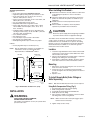
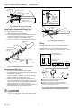
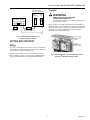
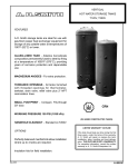
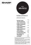
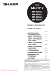
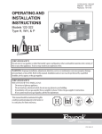
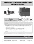
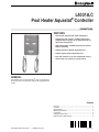
L4031A,C
Pool Heater Aquastat® Controller
PRODUCT DATA
FEATURES
• Pool control regulates pool water temperature.
• L4031A pool side control is ambient-temperature
compensated so changes in air temperature do not
affect water temperature.
• High limit provides shutdown protection to prevent
boiler overheating.
• L4031A provides automatic high limit reset.
• L4031C requires manual high limit reset.
• Each limit control has its own remote-bulb sensing
element and snap switch for system control.
GENERAL
The L4031A,C Pool Heater Aquastat® units are designed to
control pool water temperatures and provide high limit boiler
control.
Contents
General ...............................................................................
Features ..............................................................................
Specifications ......................................................................
Ordering Information ...........................................................
Installation ...........................................................................
Setting and Checkout ..........................................................
Material Safety Data Sheets ...............................................
Copyright © 1995 Honeywell Inc. • All Rights Reserved
1
1
2
2
3
5
6
60-2107-5
L4031A,C POOL HEATER AQUASTAT® CONTROLLER
Differential:
L4031A: Fixed 2°F (1°C) or 5°F (3°C). When 5°F (3°C),
the electrical rating is the High Limit Electrical Rating.
L4031C: Fixed 5°F (3°C).
SPECIFICATIONS
IMPORTANT
The specifications given in this publication do not
include normal manufacturing tolerances. Therefore,
this unit may not exactly match the listed
specifications. Also, this product is tested and
calibrated under closely controlled conditions, and
some minor differences in performance can be
expected if those conditions are changed.
Electrical Rating:
L4031A:
Pilot Duty: 125 VA at 120 and 240 Vac.
Powerpile® (millivoltage): 0.25A at 0.25 to 12 Vdc.
L4031C: Same as high limit.
Bulb Mounting:
For list of compression fittings and immersion wells, refer to
form 68-0040, Wells and Fittings for Temperature Controllers.
Order separately.
Models:
L4031A Pool Heater Aquastat® Controller controls pool
water temperature and provides automatic reset high
limit boiler control.
L4031C Pool Heater Aquastat® Controller controls pool
water temperature and provides manual reset high limit
boiler control.
Length of Capillary:
Standard, each 66 in. (1676 mm).
Case Dimensions:
See Fig. 1.
High Limit
Range:
L4031A: 100°F to 240°F (38°C to 116°C) (each division
represents 5°F degrees).
L4031C: 110°F to 290°F (43°C to 143°C) (each division
represents 5°F degrees).
Switch Action:
Each control opens on a temperature rise.
Control Point Setting:
Visible scale that can be set with an external screwdriver
adjustment.
Differential:
L4031A: Fixed 5°F (3°C).
L4031C: Manual reset.
Finish:
Gray.
Electrical Rating (A):
120 Vac
240 Vac
Full Load
8.0
5.1
Locked Rotor
48.0
30.6
Mounting Means:
Three holes in back of case.
Wiring Knockouts:
Four, for 1/2 in. conduit.
Powerpile ® (millivoltage) is 0.25A at 0.25 to 12 Vdc.
Approvals:
Underwriters Laboratories Inc. Component Recognized:
File Number M466, Guide Number MBPR2.
American Gas Association Design Certified: Report 23-11B
(L4031A only).
Canadian Standards Association Certified: File Number
LR1620, Guide Number 400-E-O (L4031A only).
Pool Control
Range:
L4031A: 40°F to 180°F (4°C to 82°C) (each division
represents 5°F degrees).
L4031C: 100°F to 240°F (40°C to 116°C) (each division
represents 5°F degrees).
ORDERING INFORMATION
When purchasing replacement and modernization products from your TRADELINE® Wholesaler or your distributor, refer to the
Tradeline® Catalog or price sheets for complete ordering number, or specify—
1. Order number.
2. Compression fittings or immersion wells, if desired.
3. Optional specifications, if desired.
If you have additional questions, need further information, or would like to comment on our products or services, please write or
phone:
1. Your local Honeywell Residential Sales Office (check the white pages of your phone directory).
2. Residential Division Customer Relations
Honeywell, 1885 Douglas Drive North
Minneapolis, Minnesota 55422-4386
In Canada—Honeywell Limited/Honeywell Limitée, 35 Dynamic Drive, Scarborough, Ontario M1V 4Z9. International Sales
and Service offices in all principal cities of the world.
60-2107—5
2
L4031A,C POOL HEATER AQUASTAT® CONTROLLER
Optional Specifications:
L4031A:
— Pool control dial marked WARMER-COOLER.
— High limit capillary exiting from top or bottom of case.
— Pool control range: 53°F to 107°F (12°C to 42°C),
100°F to 240°F (38°C to 116°C).
— Factory-set pool control limits set at 115°F, 180°F, and
200°F (46°C, 82°C, and 93°C).
— 5°F (3°C) differential on pool control.
— Adjustable differential on high limit control.
— Factory high limit stops set at 140°F, 145°F, 180°F,
195°F, 200°F, and 210°F (60°C, 63°C, 82°C, 91°C,
93°C, and 99°C).
— Capillary lengths available at 16-1/2 (high limit only),
18, 30 (pool control only), 33, 40, and 96 in. (419, 457,
762, 838, 1016, and 2438 mm).
— Case marked “Tankstat.”
— No openings in cover.
— Less dial stops on pool control or both sides.
— No opening over high limit dial.
— With adjusting knob on pool control; less jumper.
When Installing this Product…
� Read these instructions carefully. Failure to follow them
could damage the product or cause a hazardous
condition.
� Check the ratings given in the instructions and on the
product to make sure the product is suitable for your
application.
� Installer must be a trained, experienced service
technician.
� After installation is complete, check out product
operation as provided in these instructions.
CAUTION
Disconnect power supply before beginning installation
to prevent electrical shock or equipment damage.
The L4031 can be mounted either vertically or horizontally on
a wall or panel, or directly on a tank. This device can be
installed with the case and bulbs as far apart as the tubing
permits. In all cases, the equipment manufacturer directions
should be followed, if available. If not, follow the general
instructions in the Location section.
L4031C:
— Factory high limit stop set at 250°F (121°C).
NOTE: Not all combinations of options are available. For
information, contact your Honeywell Sales
Representative or TRADELINE® Dealer.
SIDE VIEW
Location
1. Locate the high limit bulb in the hot water outlet header
of the heater. Locate the pool control bulb in the return
water header of the heater.
2. Uncoil no more tubing than needed. Sharp or repeated
bending of the tubing can cause damage.
3. If the tubing is subjected to vibration, protect it against
wear when it comes in contact with another surface.
FRONT VIEW
3/8 (10) DIA.
11/16
(17)
Mounting
4-1/2
(114)
1. Remove the cover by loosening the cover screw on the
lower front of the controller.
2. Fasten the case to a convenient wall or panel with
screws through the three mounting holes in the back of
the case.
3. Replace cover.
5-7/8
(149)
2-1/4 (57)
To Install Remote Bulb (Order Fittings or
Wells Separately)
3-3/8 (86)
4-1/8 (105)
NOTE: Bulb must be bottomed in well for correct response.
M4537
Using Bulb Compression Fitting (Fig. 2)
Fig. 1. Dimensions of L4031 in in. (mm).
1.
2.
3.
4.
5.
INSTALLATION
WARNING
CAN CAUSE PROPERTY DAMAGE,
SEVERE INJURY OR DEATH.
This product is intended for use only in systems with a
pressure relief valve.
Screw the fitting into boiler or pipe tapping.
Slide sealing washer onto bulb.
Insert bulb into boiler fitting until bulb bottoms.
Slide split sleeve into fitting.
Place clamps A and B on assembly so sleeve is drawn
into fitting when screws are tightened.
NOTE: Make sure that nub on clamp A engages space
between sleeve and clamp.
6. Tighten clamp screws evenly.
3
60-2107—5
L4031A,C POOL HEATER AQUASTAT® CONTROLLER
CLAMP B
CLAMP SCREWS (2)
CLAMP A
BULB
COMPRESSION
FITTING
BULB
SEALING
WASHER
JAWS
SPREAD JAWS
TO FIT OVER
RIDGE ON SPUD
OF WELL
INSERTION LENGTH
APPROX. 3-3/16 in. (81 mm)
SPLIT SLEEVE
SCREWDRIVER
M8815
INSERT— MOUNTING CLAMP
Fig. 2. 104486 Bulb compression fitting.
DRAW
NUT
Using Capillary Compression Fitting (Fig. 3)
MOUNTING
CLAMP
B
1.
2.
3.
4.
Screw fitting into boiler or pipe tapping.
Place packing nut on tubing.
Slide bulb completely through fitting.
Place composition disk and four slotted brass washers
on tubing in the order shown in Fig. 3. Turn brass
washers so that slots are 180 degrees apart.
5. Slide seal assembly into fitting and tighten packing nut.
SPUD
WELL
BULB
TUBING
M8777
A
Fig. 4. Immersion well fitting.
IMMERSION
BULB
Wiring
BOILER PLUG
All wiring must comply with local codes and ordinances.
CAPILLARY TUBING
In all installations, follow the equipment manufacturer
instructions. If not available, use hookups in Figs. 5, and 6.
COMPOSITION DISK
(SLOTTED)
POOL
CONTROL
PACKING NUT
HIGH
LIMIT
EXAMPLE OF SLOTTED WASHERS
ASSEMBLED
IN PAIRS:
L4031 POOL HEATER
AQUASTAT® CONTROLLER
REVERSE-ACTING
PRESSURE
PILOTSTAT
CONTOLLER
M8816
GAS VALVE
2
Fig. 3. 104484 Capillary compression fitting.
Using Immersion Well (Fig. 4)
PUMP
1. Screw the well into the boiler or pipe tapping.
2. Insert the bulb into the well, pushing the tubing until the
bulb bottoms in the well.
3. Attach the retainer clamp to the end of the well spud.
Loosen the draw nut and spread the jaws of the clamp
with a screwdriver if necessary. See Fig. 4.
4. With the retainer clamp attached to a well spud (be
sure jaws of clamp hook over the ridge at the end of the
spud, as shown at point A), adjust tubing to fit through
retainer clamp groove, as shown at point B.
5. Tighten draw nut so retainer clamp is firmly attached to
well spud and tubing is held securely in place.
HEATING
SWITCH
1
L1
(HOT)
L2
1
POWER SUPPLY. PROVIDE DISCONNECT MEANS AND
OVERLOAD PROTECTION AS REQUIRED.
2
WHEN HIGH LIMIT AND POOL CONTROL ARE CONNECTED IN
SERIES, CURRENT DRAW OF CIRCUIT MUST NOT EXCEED
ELECTRICAL RATING OF POOL CONTROL.
M4539
Fig. 5. Typical L4031 connection providing pool
temperature control and high limit protection.
CAUTION
Do not secure draw nut so tightly that retainer clamp
could collapse tubing
60-2107—5
PUMP
SWITCH
4
L4031A,C POOL HEATER AQUASTAT® CONTROLLER
Checkout
L4031 POOL HEATER
AQUASTAT® CONTROLLER
POOL
CONTROL
WARNING
HIGH
LIMIT
CAN CAUSE PROPERTY DAMAGE,
SEVERE INJURY OR DEATH.
This product is intended for use only in systems with a
pressure relieve valve.
GAS BURNER CONTROL
PP
PP
POWERPILE®
GENERATOR
TH1
TH2
Always conduct a thorough checkout when the installation is
complete. Make sure the controller was installed and adjusted
properly by putting it into operation and observing at least one
complete cycle. Further adjustment can then be made to
provide for more exact requirements.
REVERSE-ACTING
PRESSURE CONTOLLER
M4538
Fig. 6. Typical L4031 connection in a
self-generating gas system.
POOL CONTROL
POINT SETTING
SCREW
SETTING AND CHECKOUT
HIGH LIMIT
CONTROL POINT
SETTING SCREW
Setting
To set the control point of each control, insert a screwdriver in
the slotted head visible through the cover, and turn the dial of
each control to the desired setting (Fig. 7).
M4540
Because systems differ, the correct setting for one system
may not apply to another. In all cases, the equipment manufacturer recommendations for setting should be followed.
Fig. 7. Internal closeup view of L4031A pool heater
Aquastat® Controller setting screws.
5
60-2107—5
L4031A,C POOL HEATER AQUASTAT® CONTROLLER
1-888-809-3787
60-2107—5
6
L4031A,C POOL HEATER AQUASTAT® CONTROLLER
7
60-2107—5
L4031A,C POOL HEATER AQUASTAT® CONTROLLER
1-888-809-3787
60-2107—5
8
L4031A,C POOL HEATER AQUASTAT® CONTROLLER
9
60-2107—5
L4031A,C POOL HEATER AQUASTAT® CONTROLLER
60-2107—5
10
L4031A,C POOL HEATER AQUASTAT® CONTROLLER
11
60-2107—5
L4031A,C POOL HEATER AQUASTAT® CONTROLLER
Home and Building Control
Honeywell Inc.
Honeywell Plaza
P.O. Box 524
Minneapolis, MN 55408-0524
60-2107—5
J. H.
Home and Building Control
Honeywell Limited-Honeywell Limitée
740 Ellesmere Road
Scarborough, Ontario
M1P 2V9
Rev. 5-95 Printed in U.S.A.
12
Helping You Control Your World
QUALITY IS KEY
customer.honeywell.com