1
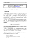
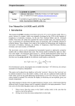
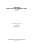
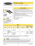
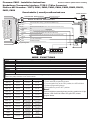
Check for firmware updates before installing
Firmware: PKH3 - Installation Instructions
Honda/Acura Transponder Interface: TYPE-C (7 Wire Connector)
Platform #05 firmware:- *PKT2, PKH1, PKH2, PKH3, PKH4, PKN2, PKM2, PKHY1,
PKG3, PKG8
Downloadable @ www.XpressDownload.com
*Default Firmware
Blue
Ignition Input from ECM (See Vehicle Wire List for Pin # and Wire Color)
Violet/White
N/C
Violet
Data (See Vehicle Wire List for Pin # and Wire Color)
Pink/White
Ignition Out (See Vehicle Wire List for Pin # and Wire Color)
Pink
Ignition Input from ECM (See Vehicle Wire List for Pin # and Wire Color)
Orange
N/C
Red
(+)12 VOLT CONSTANT
Black
CHASSIS GROUND
SYSTEM
REMOTE
D2U
P.C.
Ground output when running (-) (remote start installations only)
N/C
Green
Programming
LED
USB
Data 2 Data (Optional)
2
Brown (-)
10 PIN HARNESS
This bypass kit / Data Bus Interface part has been tested
on the listed vehicles. Other vehicles will be added to the
select vehicle list upon completion of compatibility
testing. Visit website for latest vehicle application guide.
DISCLAIMER: Under no circumstances shall the
manufacturer or the distributors of the bypass kit / data
bus interface part(s) be held liable for any consequential
damages sustained in connection with the part(s)
installation. The manufacturer and it’s distributors will
not, nor will they authorize any representative or any
other individual to assume obligation or liability in
relation to the by passkit / data bus interface part(s) other
than its replacement.
OR
Programming
Interface
Upgrade (Optional)
1
Programming button
TO ECM
12 3 4 5 6 7
Front view of connector
10 PIN HARNESS
Brown
Green
Blue
Violet/White
Violet
Pink/White
Pink
Orange
Red
Black
D2U
WIRE FUNCTIONS
This connector has dual functions: 1) XKLOADER Firmware Upgrades. 2) 4 Pin Data 2 Data connector to remote system, which replaces
wire to wire (w2w) connection on the 10 Pin Harness.
VEHICLE
Acura EL 1.7
2005 - 01
Ground output when running (-) (remote start installations only)
N/C
Ignition Input from ECM (See Vehicle Wire List for Pin # and Wire Color)
N/C
Data
Ignition Out (See Vehicle Wire List for Pin # and Wire Color)
Ignition Input from ECM (See Vehicle Wire List for Pin # and Wire Color)
N/C
(+)12 VOLT CONSTANT
CHASSIS GROUND
Data (Code)
Ignition
Ground (Gnd)
Red/Blue
Pos.:#2
Black/Yellow
Pos.:#6
Brown/ Yellow
Pos.:#1
Acura MDX
2005 - 03
Red
Pos.:#2
Green/White
Pos.:#6
Brown/ Yellow
Pos.:#1
Acura RSX
2005 - 02
Red/Blue
Pos.:#2
Black/Yellow
Pos.:#6
Brown/ Yellow
Pos.:#1
Acura TSX
2005 - 03
Red/Blue
Pos.:#2
Black/Yellow
Pos.:#6
Brown/ Yellow
Pos.:#1
Acura TL
2005 - 04
Red/Blue
Pos.:#2
Black/Blue
Pos.:#6
Brown/ Yellow
Pos.:#1
Honda Accord
2005 - 03
Red/Blue
Pos.:#2
Black/Yellow
Pos.:#6
Brown/ Yellow
Pos.:#1
Honda Civic
2005 - 01
Red/Blue
Pos.:#2
Black/Yellow
Pos.:#6
Brown/ Yellow
Pos.:#1
Honda CRV
2005 - 03
White
Pos.:#2
Black/Yellow
Pos.:#6
Brown/ Yellow
Pos.:#1
Honda Element
2005 - 03
White
Pos.:#2
Black/Yellow
Pos.:#6
Brown/ Yellow
Pos.:#1
Honda Pilot
2005
Red/Green
Pos.:#2
Red/White
Pos.:#6
Brown/ Yellow
Pos.:#1
Honda Odyssey
2005
Red/Blue
Pos.:#2
Black/Yellow
Pos.:#6
Black
Pos.:#1
Honda Ridgeline
2006
Red/Blue
Pos.:#2
Black/Green
Pos.:#6
Brown/ Yellow
Pos.:#1
Module Programming
1. Press and hold programming button.
2. Turn the ignition key to the “ON” position, the LED will blink.
3. Release programming button.
4.Turn ignition key to the “OFF” position.
Reset
Press and hold programming button and plug module into 10 pin
harness, LED comes ON. When LED goes OFF, release
program button.