1
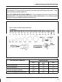
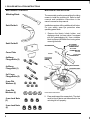
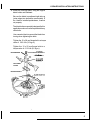
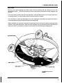
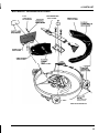
!I
1. DEALER INSTALLATION INSTRUCTIONS
The installation of this kit must be performed by an authorized Honda riding mower dealer. These
instructions are provided for dealer use.
FOLLOW THESE INSTRUCTIONS CAREFULLY. Proper installation of this kit is essential for safe,
reliable operation. Poor operation is a major cause of customer dissatisfaction. Your customer expects
this kit to be correctly installed, adjusted, and ready to use.
How to measure hardware and components:
MILLIMETERS
I
I
0
5mm
I
10
6mm
I
I
I
I
I
20
30
40
50
60
8mm
10mm
12mm
I
70
I
I
80
90
14mm
I
I
I
1
I
I
100 110 120 130 140 150
T
16 mm
INSIDE
DIAMETER
NUTS ARE SPECIFIED
BY INSIDE DIAMETER
(AT THREAD DEPTH)
WASHERS ARE
BY INSIDE DIAMETER
It
II
I
TORQUE VALUES
NUT AND BOLT DIAMETER
1
1)
ft-lb
kg-m
N•m
6 mm nuts and bolts
7.2
1.0
10
8 mm nuts and bolts
15.2
2.1
21
10 x 28 mm flange bolt (blade)
36.2
5.0
49
12 x 25 mm flange bolts ( blade holder)
61.5
8.5
83
.
I
1
1. DEALER INSTALLATION INSTRUCTIONS
MULCHING KIT CONTENTS
Mulching Blade
Swirl Guide A
Swirl Guide B
MULCHING KIT INSTALLATION
The mower deck must be removed from the riding
mower to install the mulching kit. Refer to deck
removal and installation instructions in the
owner's manual or shop manual.
Installation requires drilling additional bolt holes.
For your safety, wear eye protection when
operating power tools.
1. Remove the blade, blade holder, and
discharge chute (or lower chute if equipped
with the grass-bagging kit). Use a wooden
block to prevent the blade from turning when
removing the bolts.
BLADEWASHER
\
;k:EmgmoLT
9
-
12 x 25 mm
FLANGE BOLT(2)
Cover Plate
12 mm LOCK
WASHER
6x40mm
Flange Bolts (2)
i
6x55mm
'
BLADE HOLDER B
BLADE HOLDER A
Flange Bolt (1)
8x35mm
Flange Bolts (2)
6 mm Flat
Washers (6)
8 mm Flat
Washers (4)
H3000 Series Model Shown
2. Clean and inspect the mower deck. The deck
6 mm Lock Nuts
(3)
must be free of dents and deformities for the
mulching kit to fit properly.
8 mm Lock Nuts
(4)
2
I
1. DEALER INSTALLATION INSTRUCTIONS
3. Temporarily install the cover plate on the
mower deck, using two 8 mm lock nuts.
A-
COVER PLATE
5. Install the cover plate on the mower deck,
using two 8 mm lock nuts.
Attach swirl guide B to the cover plate, using
two 8 x 35 mm flange bolts, 8 mm flat washers,
and 8 mm lock nuts.
Install the bolts from inside the mower deck.
Install the nuts outside the mower deck. Use
washers on both sides, as shown.
Tighten all 8 mm nuts and bolts to a torque
value of 15.2 ft-lb (2.1 kg-m).
8 mm LOCK
SWIRL GUIDE B
4. Hold swirl guide B against the cover plate.
FANGE BOLT
COVER PLATE
Insert a pencil through the holes in swirl guide
B to mark drilling points on the cover plate.
Remove the cover plate from the mower deck.
Center punch and drill the cover plate at the
pencil marks.
Use an 11/32 inch (8.4 - 8.7 mm) drill. Wear
eye protection when drilling.
Remove any burrs from the holes.
SWIRL GUIDE B HOLES
6. Place swirl guide A in the mower deck, with
one end against swirl guide B.
While holding swirl guide A in place, drill the
first hole in the mower deck, using the hole in
swirl guide A as a drill guide.
Use a 1/4 inch (6.2 - 6.4 mm) drill. Wear eye
protection when drilling.
Remove any burrs from the hole.
3
1. DEALER INSTALLATION INSTRUCTIONS
7. Install a 6 x 40 mm flange bolt, 6 mm washers,
and a 6 mm lock nut in the first hole, as shown.
9. Install a 6 x 40 mm flange bolt, 6 mm washers,
and a 6 mm lock nut in the second hole, as
shown.
Tighten the 6 mm nut and bolt to a torque
value of 7.2 ft-lb (1.0 kg-m).
Tighten the 6 mm nut and bolt to a torque
value of 7.2 ft-lb (1.0 kg-m).
To assure a good fit, mower deck holes must
be drilled in sequence, and swirl guide A must
be secured with nuts and bolts before drilling
the next hole.
SWIRL GUIDE A
FLAT
iER
SECOND HOLE
6x40
FLAN(
10. Drill the third hole in the mower deck, using
the hole in swirl guide A as a drill guide.
Use a 1/4 inch (6.2 - 6.4 mm) drill. Wear eye
protection when drilling.
Remove any burrs from the hole.
11. Install a 6 x 55 mm flange bolt, 6 mm washers,
and a 6 mm lock nut in the third hole, as
shown.
Tighten the 6 mm nut and bolt to a torque
value of 7.2 ft-lb (1.0 kg-m).
6 mmFLAT
WASHERS
6 mm
LOCK
6 mm FLATv
WASHERS
8. Drill the second hole in the mower deck, using
the hole in swirl guide A as a drill guide.
Use a 1/4 inch (6.2 - 6.4 mm) drill. Wear eye
protection when drilling.
Remove any burrs from the hole.
~
4
..?
\
\
\
’\
6 x 55 mm
FLANGE BOLT
1. DEALER INSTALLATION INSTRUCTIONS
12. Install the mulching blade, using the original
blade holder and hardware.
Be sure the blade is positioned right side up
(outer edges turn toward the mower deck). If
the blade is installed upside down, it cannot
cut properly.
The blade bolts are specially designed for this
application and must not be replaced with any
other bolts.
Use a wooden block to prevent the blade from
turning when tightening the bolts.
Tighten the 10 x 28 mm flange bolt to a torque
value of 36.2 ft-lb (5.0 kg-m).
Tighten the 12 x 25 mm flange bolts to a
torque value of 61.5 ft-lb (8.5 kg-m).
BLADE WASHER
\
9-
1Ox28mm
FLANGE BOLT
FLANGE BOLT
MULCHING
BLADE
BLADE HOLDER B
I
5
2. SAFETY
SAFETY LABEL LOCATIONS (H3000 SERIES)
Read all safety instructions before operating the riding mower.
OPERATORONLY. NO PASSENGERS
OPERATION ON PUBLIC STREETS OR
HIGHWAYS IS ILLEGAL.
MOWER CAN THROW OBJECTS:
BEFORE MOWING, CLEAR LAWN OF ALL
STICKS. ROCKS. AND OTHER DEBRIS.
KEEP PEOPLE AND PETS AWAY.
AVOID TIPOMRS:
REDUCE SPEED WHEN TURNING OR
OPERATING ON SLOPES
MAXIMUM SAFE OPERATING ANGLE IS
10 DEGREES
(17% GRADE)
w
AVOID BURNS
~
~
~
MOWER BLADE MAY CAUSE INJURY :
STOP ENGINE BEFORE REMOVING GRASS
BAG OR CLEANING DISCHARGE CHUTE.
/
I
6
IPREVENT BRAKE FAILURE
I
DISENGAGE PARKING BRAKE WHEN
BUZZER SOUNDS CONTINUOUSLY
A DELAYED ENGINE CUTOFF WILL
STOP THE ENGINE IF PARKING
BRAKE IS NOT RELEASED.
GASOLINE IS FLAMMABLE.
STOP ENGINE, AVOID HEAT,
SPARKS, AND OPEN FLAME
WHEN REFUELING.
2. SAFETY
SAFETY LABEL LOCATIONS (H1000 SERIES)
Read all safety instructions before operating the riding mower.
rn Improperly driving on slopes or uneven terrain can cause the mower to tip
over and you can be seriously hurt or killed.
Read "Safe Mowing Practices" in the Owner's Manual carefully.
w Objects hidden in the lawn can be thrown by the blade and can cause serious
injury.
Read "Mower Safety" and "Safe Mowing Tips" in your Owner's Manual carefully.
rn The rotating blade can cause serious injury.
rn Keep hands and feet away from mower deck
rn Stop engine before leaving operator's position.
rn Do not allow children to ride as passengers.
They can fall or be thrown off causing serious injury or death.
Read "Child Safety" in the Owner's Manual carefully.
7
3. MOWING AND MULCHING RECOMMENDATIONS
GRASS CUTTlNG BASICS
Cutting Height
A cutting height setting of 1-1/2 or 2 inches is appropriate for most lawns during cool
weather. A higher cut may be needed to protect the lawn during hot summer months.
Consult a local nursery or lawn and garden center for advice about specific types of grasses
and growing conditions in your area.
Most grasses should be cut when they have grown 1/2 to 1 inch above the recommended
height. If your grass gets too tall, cut it back a little at a time, allowing a few days for the
grass to recover between mowings. Avoid cutting more than one third of total grass height
in any one mowing.
For best mulching results, mow the lawn frequently enough that you will need to cut off less
than one inch. Frequent mowing, with light cuts, makes it easier for your mulching mower
to turn grass clippings into fine particles that will fall through the turf and decompose quickly.
Cutting Width
For an even lawn finish, overlap each mowing swath by a few inches. If the grass is very
tall or thick, use more overlap and a narrower mowing swath. If clogging or clumping
occurs, you may also need to mow more slowly or raise the cutting height setting.
Blade Speed
For best performance, the blade must spin very fast. Always use the fast throttle setting,
and keep the engine running at or near maximum rpm. If you hear engine speed decrease,
mow more slowly, cut a narrower swath, or raise the cutting height setting.
Blade Sharpness
Keep the blade sharp. A sharp blade cuts cleanly. A dull blade tears the grass, leaving
shredded ends that turn brown.
Moisture
Always wait for wet grass to dry. Wet grass clippings will clog the mower deck and collect in
clumps on the lawn.
If the soil is very dry, mowing can stir up a lot of dust. Besides being unpleasant to work in,
too much dust will clog the carburetor air filter. If dust is a problem, water your lawn the day
before mowing. Mow when the grass dries, and the soil is still moist.
8
3. MOWING AND MULCHING
MULCHING
Mulching cuts grass clippings and fallen leaves into fine particles that fall through the turf and
decompose quickly. This returns nutrients to the soil and reduces'the need for raking, bagging, and
disposal.
For best mulching results, mow the lawn frequently, cutting off less than one inch of grass each time.
In growing season, you will probably need to mow the lawn twice a week.
This mulching kit closes the discharge port in the mower deck and adds swirl guides that help to
recirculate grass clippings through the special mulching blade.
Dealer installation is necessary, because the mower deck and mulching cover plate must be precisely
drilled for swirl guide attachment. After the initial installation, the cover plate and swirl guide B can be
easily removed, if you decide to convert the mower deck for side-discharge or bagging use.
H3000 Series Model Shown
9
3. MOWING AND MULCHING RECOMMENDATIONS
SIDE-DISCHARGE MOWING
Side-discharge mowing should be considered where grass has grown too tall to mulch easily.
Side-discharge mowing will leave grass clippings on top of the mowed areas and may need to be
removed by raking. Heavy clumps of clippings should always be removed; grass must remain uncovered
to grow properly.
For side-discharge mowing, you must remove the mower deck cover plate and swirl guide B, then install
the original discharge chute. It is not necessary to remove or replace other parts of the mulching kit.
Objects thrown by the blades can cause serious
injury. Disengage the Power Take Off (PTO) and
shut off the engine, before removing and installing
parts.
Before operating the riding mower, be sure the
mower deck cover plate or the discharge chute is
properly installed.
Conversion for Side-Discharge Mowing:
1. Lower the mower deck, and remove the two
8mm lock nuts from the top of the cover
plate.
2. Raise the mower deck, and remove the two
8 x 35 mm bolts, two nuts, and four
washers from the side of the cover plate.
3. Remove the cover plate and swirl guide B.
4. Install the original discharge chute, using
the two 8 mm lock nuts.
5. Tighten the 8 mm lock nuts to a torque
value of 15.2 ft-lb (2.1 kg-m).
Cover Plate Reinstallation for Mulching:
1. Lower the mower deck, and remove the two
8 mm lock nuts from the discharge
chute. Remove the chute.
2. Install the cover plate on the mower deck,
using the two 8 mm lock nuts.
Tighten the 8 mm lock nuts to a torque
value of 15.2 ft-lb (2.1 kg-m).
3. Raise the mower deck, and install swirl
guide B on the cover plate, using two 8 x
35 mm bolts, four 8 mm flat washers, and
two 8 mm lock nuts, as shown.
Tighten the 8 mm nuts and bolts to a torque
value of 15.2 ft-lb (2.1 kg-m).
10
3. MOWING AND MULCHING
~~
~
BAGGING
Bagging should be considered for areas where you want the lawn to be clear of loose particles, such
as around swimming pools, and for less frequently mowed areas, where grass has grown too tall to
mulch easily.
For bagging, you must remove the mower deck cover plate and swirl guide B, then install the bagging
kit. It is not necessary to remove or replace other parts of the mulching kit, but a high-lift blade can be
installed to increase bagging performance if desired.
Objects thrown by the blades can cause serious
injury. Disengage the Power Take Off (PTO) and
shut off the engine, before removing and installing
parts.
Before operating the riding mower, be sure the
mower deck cover plate or the bagging kit is
properly installed.
Conversion for Bagging:
8 mm LOCK NUT (2)
1. Lower the mower deck, and remove the
two 8 mm lock nuts from the top of the
cover plate.
2. Raise the mower deck, and remove the two
8 x 35 mm bolts, two nuts, and four
washers from the side of the cover plate.
3. Remove the cover plate and swirl guide B.
4. Install the bagging kit lower chute, using
two 8 mm lock nuts and flat washers.
Tighten the 8 mm lock nuts to a torque
value of 15.2 ft-lb (2.1 kg-m).
LOWER CHUTE
11
1
3. MOWING AND MULCHING RECOMMENDATIONS
5. Install the bag support assembly on the left
and right struts, while inserting the center
strut pin in the the hitch plate hole.
6. Grasp the upper chute by the chute handle.
Raise the upper and middle chutes, then
slide the middle chute over the lower chute.
7. Install the grass bags, and secure the
hopper top with its retaining band.
Cover Plate Reinstallation for Mulching:
1. Remove the bagging kit in the reverse
order of installation.
CHUTE HANDLE
2. Install the cover plate, using the two 8 mm
lock nuts. Refer to the illustration on page
10. Tighten the 8 mm nuts to a torque
value of 15.2 ft-lb
(2.1 kg-m).
3. Install swirl guide B on the cover plate,
using two 8 x 35 mm bolts, four 8 mm flat
washers, and two 8 mm lock nuts, as
shown. Tighten the 8 mm nuts and bolts to
a torque value of 15.2 ft-lb (2.1 kg-m).
LOWER CHUTE
12
/
4. PARTS LIST
MULCHING KIT: Part Number 06764-763-ROO
8mm
LOCK NUT (4)
90115-659-003
MULCHING BLADE
72511-763-R00
8 mm FLAT
SWIRL GUIDE A
76267-763-R00
COVER PLATE
76264-763-M00
SWIRL GUIDE B
76268-763-R00
90102-763-R00
H3000 Series Model Shown
13
5. WARRANTY SERVICE
OWNER SATISFACTION
Your satisfaction and good will are important to your dealer and to us. All Honda warranty details are
explained in the Distributor’s Limited Warranty. Normally any problems concerning the product will be
handled by your dealer’s service department. If you have a warranty problem that has not been handled
to your satisfaction, we suggest you take the following action:
Discuss your problem with a member of the dealership management. Often complaints can be
quickly resolved at that level. If the problem has already been reviewed with the Service Manager,
contact the owner of the dealership or the General Manager.
If your problem still has not been resolved to your satisfaction, contact the Power Equipment
Customer Service Department of American Honda Motor Co., Inc.
American Honda Motor Co., Inc.
Power Equipment Customer Service Department
4475 River Green Pkwy.
Duluth, Georgia 30136
Telephone: (404) 497-6400
We will need the following information to assist you:
- Your name, address, and telephone number
- Product model and serial number
- Date of purchase
- Dealer name and address
- Nature of problem
After reviewing all the facts involved, you will be advised of what action can be taken. Please bear in
mind that your problem will likely be resolved at the dealership, using the dealer’s facilities, equipment,
and personnel, so it is very important that your initial contact be with the dealer.
Your purchase of a Honda product is greatly appreciated by both your dealer and American Honda Motor
Co., Inc. We want to assist you in every way possible to assure your satisfaction with your purchase.
14
Current customer service contact information:
United States, Puerto Rico, and U.S. Virgin Islands:
Honda Power Equipment dealership personnel are trained professionals. They should
be able to answer any question you may have. If you encounter a problem that your
dealer does not solve to your satisfaction, please discuss it with the dealership's
management. The Service Manager or General Manager can help. Almost all problems
are solved in this way.
If you are dissatisfied with the decision made by the dealership's management, contact
the Honda Power Equipment Customer Relations Office. You can write:
American Honda Motor Co., Inc.
Power Equipment Division
Customer Relations Office
4900 Marconi Drive
Alpharetta, GA 30005-8847
Or telephone: (770) 497-6400 M-F, 8:30 am - 5:00 pm EST
When you write or call, please provide the following information:
•
Model and serial numbers
•
Name of the dealer who sold the Honda power equipment to you
•
Name and address of the dealer who services your equipment
•
Date of purchase
•
Your name, address, and telephone number
•
A detailed description of the problem