1
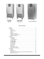
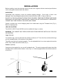
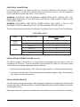
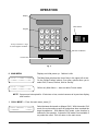
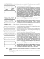
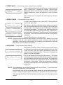
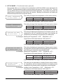
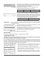
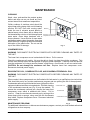
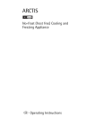
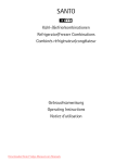
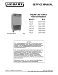
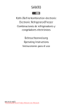
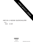
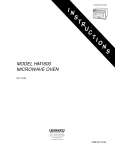
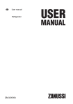
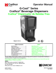
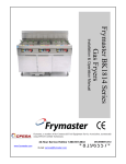
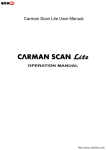
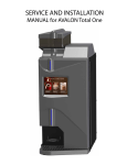
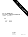
HQC45 QUICKCHILL,
HQCF45 QUICKCHILL / FREEZER &
HQC90 QUICKCHILL
MODEL
HQC45
HQCF45
HQC90
ML-124061
ML-124062
ML-124063
701 S. RIDGE AVENUE
TROY, OHIO 45374-0001
937 332-3000
www.hobartcorp.com
FORM 34523 (July 2000)
Model HQC45
QuickChill
With Legs
Model HQCF45
QuickChill / Freezer
With Casters
Model HQC90 QuickChill
Table of Contents
General . . . . . . . . . . . . . . . . . . . . . . . . . . . . . . . . . . . . . . . . . . . . . . . . . . . . . . . . . . . 3
Installation . . . . . . . . . . . . . . . . . . . . . . . . . . . . . . . . . . . . . . . . . . . . . . . . . . . . . . . . 4
Uncrating . . . . . . . . . . . . . . . . . . . . . . . . . . . . . . . . . . . . . . . . . . . . . . . . . . . . . . 4
Legs or Casters . . . . . . . . . . . . . . . . . . . . . . . . . . . . . . . . . . . . . . . . . . . . . . . . . 4
Location . . . . . . . . . . . . . . . . . . . . . . . . . . . . . . . . . . . . . . . . . . . . . . . . . . . . . . . 5
Features . . . . . . . . . . . . . . . . . . . . . . . . . . . . . . . . . . . . . . . . . . . . . . . . . . . . . . . 5
Electrical Connections . . . . . . . . . . . . . . . . . . . . . . . . . . . . . . . . . . . . . . . . . . . 6
Installation of Remote Alarm . . . . . . . . . . . . . . . . . . . . . . . . . . . . . . . . . . . . . . 6
Installation Checkout . . . . . . . . . . . . . . . . . . . . . . . . . . . . . . . . . . . . . . . . . . . . . 6
Operation . . . . . . . . . . . . . . . . . . . . . . . . . . . . . . . . . . . . . . . . . . . . . . . . . . . . . . . . . 7
0. Main Menu . . . . . . . . . . . . . . . . . . . . . . . . . . . . . . . . . . . . . . . . . . . . . . . . . . . 7
1. Chill Mode . . . . . . . . . . . . . . . . . . . . . . . . . . . . . . . . . . . . . . . . . . . . . . . . . . . 7
1.1 Automatic Chill . . . . . . . . . . . . . . . . . . . . . . . . . . . . . . . . . . . . . . . . . . . . . . 8
1.2 Manual Chill . . . . . . . . . . . . . . . . . . . . . . . . . . . . . . . . . . . . . . . . . . . . . . . . . 8
2. Freeze Mode . . . . . . . . . . . . . . . . . . . . . . . . . . . . . . . . . . . . . . . . . . . . . . . . . 9
3. Defrost Mode . . . . . . . . . . . . . . . . . . . . . . . . . . . . . . . . . . . . . . . . . . . . . . . . . 9
4. Hold Mode . . . . . . . . . . . . . . . . . . . . . . . . . . . . . . . . . . . . . . . . . . . . . . . . . . . 9
5. Set Up Mode . . . . . . . . . . . . . . . . . . . . . . . . . . . . . . . . . . . . . . . . . . . . . . . . 10
Print Mode . . . . . . . . . . . . . . . . . . . . . . . . . . . . . . . . . . . . . . . . . . . . . . . . . . . . 11
Printer Paper . . . . . . . . . . . . . . . . . . . . . . . . . . . . . . . . . . . . . . . . . . . . . . . . . . 11
Loading Printer Paper . . . . . . . . . . . . . . . . . . . . . . . . . . . . . . . . . . . . . . . . . . . 11
Setting the Time and Date . . . . . . . . . . . . . . . . . . . . . . . . . . . . . . . . . . . . . . . 11
Maintenance . . . . . . . . . . . . . . . . . . . . . . . . . . . . . . . . . . . . . . . . . . . . . . . . . . . . . . 12
Cleaning . . . . . . . . . . . . . . . . . . . . . . . . . . . . . . . . . . . . . . . . . . . . . . . . . . . . . . 12
Condenser Coil . . . . . . . . . . . . . . . . . . . . . . . . . . . . . . . . . . . . . . . . . . . . . . . . 12
Evaporator Coil, Condensate Loop, and Condensate Removal Pan . . . . . . 12
Maintenance Program . . . . . . . . . . . . . . . . . . . . . . . . . . . . . . . . . . . . . . . . . . . 12
© HOBART CORPORATION 1992, 1996, 1999
–2–
Installation, Operation, Use and Care of
HQC45 QuickChill, HQCF45 QuickChill / Freezer,
& HQC90 QuickChill
SAVE THESE INSTRUCTIONS
GENERAL
The HQC45 QuickChill is designed for rapid chilling of 45 pounds of food (9 pounds of food per pan
in five 12" x 20" x 21⁄2" pans or five 18" x 26" sheet pans) from 150°F to 37°F in approximately 90 minutes.
The rapid chilling process preserves food quality, texture and nutritional value for up to 5 days. As
many as 5 chillings can be handled per 8 hour shift. The Automatic Chill/Hold mode can be used for
overnight chilling.
The HQCF45 QuickChill / Freezer is designed to chill exactly like the HQC45 and it can also freeze
product down to – 20°F. Freezing time varies according to the initial and final product temperatures
as well as product type and quantity. Coated wire shelves can accommodate five full-size
12" x 20" x 21⁄2" pans or five 18" x 26" sheet pans.
The HQC90 QuickChill is designed for rapid chilling of 90 pounds of food (9 pounds of food per pan
in ten 12" x 20" x 21⁄2" pans) from 150°F to 37°F in approximately 90 minutes. Optional coated wire
shelves can accommodate ten full-size 12" x 20" x 21⁄2" pans or five 18" x 26" x 21⁄2" pans.
Chill and Freeze times are dependent upon product type, thickness, density, thermal conductivity, and
type of covering. For best results, approximately 9 pounds of product per 12" x 20" x 2 1⁄2" pan or
18" x 26" sheet pan is recommended. If more product per pan is being chilled, the time required to
chill will be increased.
Cabinets are provided with a junction box in the lower section which allows for permanent, hard-wire
connection. Stainless steel legs or casters are available accessories.
The durable stainless steel interior has coved corners for ease of cleaning. The exterior sides, front,
and back are stainless steel. Left or right door swing is available on order and cannot be changed in
the field. Compressors supplied by Hobart are rated 11⁄4 HP on HQC45 and HQCF45. Compressors
are rated 13⁄4 HP on HQC90. Refrigerant is R404A. Remote refrigeration system or water cooled
refrigeration system are optional.
The microprocessor controller provides the ability to:
• Select the mode of operation from a standard menu: Automatic (probe) or timed chill or freeze.
• Display the current air and product temperatures and time.
• Monitor product temperature with three probes during chill mode to reduce chances of freezing.
• Allows the operator the choice of enabling surface protection that will limit the air temperature
to 28°F in the latter part of the chill cycle.
• Provide service diagnostics to quickly check machine functions and control circuitry; provides
quick connect/disconnect of the controller.
The printer is part of the controller and provides the ability to:
• Print data from the last chill cycle or from all chill cycles since 12:00 midnight.
• Print the time and date information for each cycle.
• Report chill temperatures vs. time at ten minute intervals.
–3–
INSTALLATION
Before installing, check the electrical service to make sure it agrees with the electrical specifications
on the rating plate located inside the cabinet.
UNCRATING
Immediately after unpacking, check for possible shipping damage. If the chiller is found to be
damaged, save the packaging material and contact the carrier within 15 days of delivery.
DO NOT LAY THE CHILLER ON ITS FRONT, BACK OR SIDES. EXERCISE EXTREME CARE WHEN
REMOVING THE CRATE BOTTOM ESPECIALLY WHEN THE LAST SHIPPING BOLT IS REMOVED.
CABINET MUST BE PROPERLY BLOCKED AND STABLE.
Cabinet is bolted onto a wood shipping base from underneath using the Threaded Hole (Fig.1).
Remove shipping bolts.
LEGS OR CASTERS
The HQC45, HQCF45 and HQC90 must be installed with legs or casters.
WARNING: THE CABINET MUST BE BLOCKED AND STABLE BEFORE INSTALLING THE LEGS
OR CASTERS.
Legs (Optional)
To install the legs, raise up and block the cabinet a minimum of 7" from the floor and thread the legs
into the threaded holes on the bottom of the cabinet.
The chiller must be level to operate properly. Turn the adjustable feet in or out as required to level the
chiller front-to-back and side-to-side (Fig. 1).
Casters (Optional)
Casters may be supplied for use on self-contained units. The swivel casters with brake should be
installed in front; casters without brake, in rear (Fig. 2). Caster equipped chillers should be located on
a level floor.
PL-50909
Fig. 1
Fig. 2
–4–
LOCATION
Good air circulation at the condenser coil in the lower section is necessary to provide proper operation.
The cabinet may be located in any one of the following three ways to assure satisfactory performance.
• The unit can be situated so the lower back section is open to room air, allowing free air discharge.
No side clearance and no top clearance is required. This is the preferred situation and provides
the most effective cooling.
• The unit can be provided with no side clearance, two inches of clearance at the rear, and six inches
of clearance above.
• If the unit is situated with no back clearance and no top clearance, it is necessary to provide either
five inches of clearance on each side or ten inches of clearance on one side of the cabinet.
NOTE: Performance is enhanced when the air going into the condenser coil through the lower front
section is cool. For example, locating the chiller adjacent to an oven would not be recommended.
FEATURES
Shelves (Set of Five)
A set of five shelves is optional on HQC90. A set of five shelves is standard with HQC45 and HQCF45.
Shelf clips are packed with the shelves. For each shelf, insert two front shelf clips and two rear shelf
clips into the pilaster slots at the same height. After installing shelf clips on pilasters, place shelves
on clips.
Optional single shelves are available; up to eight shelves can be installed in the cabinet at one time.
Recommended Pans
Full size 12" x 20" x 21⁄2" pans or 18" x 26" sheet pans are recommended. Pans are not included.
Probes
During a chill cycle, insert probes in pans of food to
monitor temperatures. Probes should not touch
bottom of pan. Place probe in the middle of the food
for best temperature indication.
The Top Probe in the cabinet corresponds to the left
temperature in the display (Fig. 4); the Center
Probe is second; and the Bottom Probe is the third
temperature in the display.
Top
Probe
Center
Probe
Bottom
Probe
34
32
31
AIR=34 HLD 1:35:54
Fig. 3
Door Switch
The cabinet is equipped with a door switch which shuts off the fans and refrigerant valve when the door
is opened. A buzzer sounds and a notice displays: CABINET DOOR OPEN. After the door is closed,
timer and chiller operations resume.
Fan Door Switch
A fan door switch also shuts the fans and refrigerant valve off if the metal fan grill is not properly
fastened in place. A notice displays: FAN DOOR OPEN.
Control Box Keys
Two keys for the control box lock are shipped with the chiller. These keys should be retained by the
operator when access is needed for installation of printer paper, etc.
–5–
ELECTRICAL CONNECTIONS
Line voltage supplied to the cabinet junction box must not be affected by the operation of other
electrical equipment. Junction box is located at the rear of the lower section. The rear compressor
cover is maintained in place with Velcro. Pull to remove it.
WARNING: ELECTRICAL AND GROUNDING CONNECTIONS MUST COMPLY WITH THE
APPLICABLE PORTIONS OF THE NATIONAL ELECTRICAL CODE AND/OR OTHER LOCAL
ELECTRICAL CODES.
WARNING: DISCONNECT ELECTRICAL POWER SUPPLY AND PLACE A TAG AT THE
DISCONNECT SWITCH INDICATING THAT YOU ARE WORKING ON THE CIRCUIT.
The circuit should be protected with a Dual Element Time-Delay Fuse or Inverse Time Circuit Breaker.
ELECTRICAL DATA
Model
Volts / Hertz / Phase
Minimum Circuit Ampacity
Maximum Protective Device
AMPS
HQC45
HQCF45
208 / 60 / 1
15
240 / 60 / 1
15
208 / 60 / 1
20
240 / 60 / 1
20
208 / 60 / 3
15
240 / 60 / 3
15
HQC90
Compiled in accordance with the National Electrical Code, NFPA 70, latest edition.
INSTALLATION OF REMOTE ALARM (Optional)
The chiller provides a connection for a remote alarm that operates when the buzzer sounds on
completion of a chill cycle. Connect to terminals on terminal block (# 5 and # 6 in the upper section
of the chiller) per the wiring diagram and these restrictions:
1. Maximum remote alarm rating: 120V - 240V at 2 amps resistive or 100 watt incandescent lamp.
2. Connection must be made of 600 volt insulated wire suitable for supply voltage. Do not use bell
wire, lamp cord or similar type wire.
INSTALLATION CHECKOUT
The self-contained refrigeration system (when equipped) is shipped fully charged with refrigerant and
requires only proper electrical connections. Remote refrigeration systems must be installed, connected,
and charged by others.
After proper electrical connections are made, place the switch next to the control in the On position.
–6–
OPERATION
Display
Main Switch
Keypad
1
2
3
STOP
4
5
6
START
NO
YES
OFF
# Key is used as "–" sign
to enter negative numbers.
7
8
9
PRINT
#
0
CLEAR
MUTE
ON
Silences the Buzzer
Printer Slot
Fig. 4
0. MAIN MENU
Displays on initial power up. Cabinet is idle.
10:35 1.CHLL 2.FRZE
3.DEFR 4.HOLD 5.SET
The Main Menu displays the time of day in the upper left corner.
On the Chiller/Freezer cabinet, five menu options allow you to
select Chill, Freeze, Defrost, Hold or Set-Up.
10:35 1.CHLL
3.DEFR 4.HOLD 5.SET
Chiller only Main Menu — does not allow Freeze mode.
NOTE: If power was interrupted for 10 minutes or less, control resumes at its previous display
and function.
1. CHILL MODE — From the main menu, press [1].
CHILL METHOD: 1.AUTO
2.MANUAL
3.EXIT
Select between Automatic or Manual Chill. With Automatic Chill
mode, the cycle continues until all food probes have reached the
target temperature. With Manual Chill mode, cycle duration is
selected by the operator. Automatic Chill mode is not available if
no probes are used. Exit will return to the main menu.
–7–
1.1 AUTOMATIC CHILL —(Controlled by probes, a non-timed chill.) From the main menu, press [1][1].
AUTOMATIC CHILL
OK TO START [YES/NO]
Bottom
Probe
Top
Probe
34
45
37
AIR=25 AUTO 01:25:45
CHILL CYCLE STOPPED
REMOVE FOOD [YES]
CHILL CYCLE DONE
REMOVE FOOD [YES]
To begin Automatic Chill, press [YES].
The top row displays the food probe temperatures. The left value
corresponds to the top probe; the right value corresponds to the
bottom probe, etc. The temperature of the air, the AUTO mode
indicator, and the chill cycle time are displayed on the bottom row.
The compressor operates to cool the air down to the selected
blasting air temperature in Chill mode. As each probe reaches the
target temperature in Chill mode, an asterisk (*) displays next to
its temperature display and the buzzer sounds for two minutes or
until the [MUTE] key is pressed. The cycle continues until all
probes have reached the target temperature.
If you press the [STOP] key during a chill cycle, the display at left
allows you to press [YES] and return to the main menu.
When the Automatic Chill ends, buzzer sounds for two minutes.
Pressing [YES] returns to the main menu. If you do not press
[YES] within two minutes, the cabinet goes to Cooler Hold mode.
1.2 MANUAL CHILL — (Timed chill cycle.) From the main menu, press [1] [2].
READY TO CHILL FOR
01 HOURS 10 MINUTES?
ENTER NEW CHILL TIME
00 HOURS 00 MINUTES?
If the chill time setting is OK, press [YES] to begin. If you want to
reset the chill time, press [CLEAR].
Enter the chill time as a pair of two-digit numbers (HH:MM) where
HH=hours and MM=minutes. Use a leading zero for single digit
numbers. Press [YES].
If the chill time setting is OK, press [YES] to begin.
READY TO CHILL FOR
00 HOURS 45 MINUTES?
54
58
AIR=35 MAN
65
01:09:59
The top row displays the food probe temperatures. The temperature
of the air, the MANUAL mode indicator, and the countdown time
are displayed on the bottom row. The compressor operates to
cool the air down to the selected blasting air temperature in Chill
mode. As each probe reaches the target temperature in Chill
mode, an asterisk (*) displays next to its temperature display and
the buzzer pulses two seconds on, two seconds off for two
minutes. The Chill cycle continues until the set time has elapsed.
CHILL CYCLE STOPPED
REMOVE FOOD [YES]
If you press the [STOP] key during a chill cycle, the display at left
allows you to press [YES] and return to the main menu.
CHILL CYCLE DONE
REMOVE FOOD [YES]
When the Manual Chill ends, the buzzer sounds for two minutes.
Pressing [YES] returns to the main menu. If you do not press
[YES] within two minutes, the cabinet goes to Hold mode.
NOTE: For better performance, precool the cabinet by operating in Hold mode prior to loading
product.
A message displays, ERR, when the probe needs to be replaced or when its temperature
is out of range.
–8–
2. FREEZE MODE — From the main menu, press [2], when available.
FREEZE METHOD:1.AUTO
2.MANUAL
3.EXIT
Freeze mode operates exactly like chill mode. Use the menus on
page 7 except CHILL is replaced by FREEZE. Different target
temperature and air set point may be entered in Set-Up Mode.
Different temperature ranges are available for chill and freeze
modes.
After a Freeze cycle is complete, the cabinet goes into Freezer
Hold mode.
3. DEFROST MODE — From the main menu, press [3].
To begin a manual defrost cycle, press [YES]. Pressing [NO] will
return to the main menu.
READY TO DEFROST
REMOVE FOOD [YES]
UNIT
COIL=6
DEFROSTING
00:18:42
DEFROST CYCLE DONE
ACKNOWLEDGE
[YES]
The top line of the display indicates defrost mode is in progress.
The coil temperature and the time remaining in the Defrost cycle
are displayed on the bottom line. Once it has begun, the Defrost
cycle cannot be stopped. The Defrost cycle ends when either the
coil temperature reaches the Defrost Termination Temperature or
when the Defrost Termination Time has elapsed (factory setting is
20 minutes). The Buzzer sounds for two minutes or until [MUTE]
is pressed.
Press [YES] and return to the main menu.
NOTE: Different factors influence the ideal frequency of defrost cycles. When you see some
frosting on the coil in the cabinet behind the louvers, a Defrost cycle should be
performed. If the Defrost cycle is skipped, air circulation in the cabinet will be reduced
and chilling or freezing times will increase.
4. HOLD MODE — From the main menu, press [4].
1. HOLDING COOLER
2. HOLDING FREEZER
34
35
AIR=34 HLD
33
01:35:45
If the cabinet is a chiller / freezer, this menu selects which holding
air temperature setting is used during a selected Hold mode. After
a chill or freeze cycle, the system automatically selects the
corresponding holding temperature. This menu is omitted if the
cabinet is a chiller only model.
The top row displays the food probe temperatures. The bottom
row displays the air temperature, the Hold mode indicator, and the
time accumulated since the Hold mode began. The compressor
operates to maintain the air temperature at the selected target
temperature in Hold mode. When the temperature is reached,
fans stop, and periodically restart to maintain a uniform internal
temperature.
NOTE: During Hold mode, an automatic Defrost occurs every six hours. To exit Hold mode,
press [STOP] and return to the main menu.
In Hold mode, quick chillers and quick feezers operate like a standard refrigerator or
freezer. Probes are ignored and air temperature is maintained at the selected value.
If the message COOLING TOO SLOW displays during Hold mode, the cabinet needs
service.
–9–
5. SET UP MODE — From the main menu, press [5].
Set Up mode allows you to easily set four parameters for HQC45, HQC90; seven parameters for
HQCF45. These parameters could be set according to the type of food, its surface, etc. The user
may try different set ups to maximize performance and food quality. On a chiller only model, the
grayed freezer temperatures setup menus are omitted. Blasting air differential and holding air
differential temperatures are set at the factory.
TARGET TEMPERATURE
IN CHILL MODE: 37
The setting for target food temperature in Chill mode is shown.
Temperature Range
Preset Target Temperature
34° F to 80° F
37° F
Chill Mode
Enter a value within the range. Press [YES] to continue.
TARGET TEMPERATURE
IN FREEZE MODE: 0
The setting for target food temperature in Freeze mode is shown.
Freeze Mode
Temperature Range
Preset Target Temperature
– 22° F to 80° F
0° F
Enter a value within the range. Press [YES] to continue.
BLASTING AIR TEMP.
IN CHILL MODE: 10
The setting for blasting air temperature in Chill mode is shown. Air
temperature will be maintained between the blasting air
temperature and blasting air temperature plus differential.
For Example: Blasting Air Temperature = 10°F.
Differential = 4 F°.
Temperature will fluctuate between 10°F and 14°F.
Temperature Range
Preset Blasting Air Temp.
10° F to 45° F
10° F
Chill Mode
Enter a value within the range. Press [YES] to continue.
BLASTING AIR TEMP.
IN FREEZE MODE: -25
The setting for blasting air temperature in Freeze mode is shown.
Air temperature will be maintained between blasting air temperature
and blasting air temperature plus the differential.
For Example: Blasting Air Temperature = –25°F.
Differential = 4 F°.
Temperature will fluctuate between –25°F and –21°F.
Freeze Mode
Temperature Range
Preset Blasting Air Temp.
– 32° F to 20° F
– 25° F
Enter a value within the range. Press [YES] to continue.
HOLDING COOLER
TEMPERATURE:
35
The setting for air temperature in Holding Cooler mode is shown.
Air temperature will be maintained between the holding cooler
temperature and holding cooler temperature plus differential.
For Example: Holding Cooler Temperature = 35°F. Differential = 6 F°.
Temperature will fluctuate between 35°F and 41°F.
Temperature Range Preset Holding Cooler Temp.
Holding Cooler Mode
10° F to 45° F
35° F
Enter a value within the range. Press [YES] to continue.
– 10 –
HOLDING FREEZER
TEMPERATURE:
-6
The setting for the air temperature in freezer hold mode is shown.
Air temperature will be maintained between the holding temperature
and holding temperature plus differential.
For Example: Holding Freezer Temperature = –6°F.
Differential = 6 F°.
Temperature will fluctuate between –6°F and 0°F.
Temperature Range Preset Holding Freezer Temp.
Freezer Hold Mode – 32° F to 20° F
– 6° F
Enter a value within the range. Press [YES] to continue.
SURF PROTECTION: OFF
1=ON
2=OFF
This applies only when operating in a Chill mode. When ON, the
blasting air temperature is raised to 28°F during the last third of a
timed (manual) chill cycle or when all three probes are within 5 F°
of the target temperature during an automatic chill cycle.
Range of Acceptable Values
Preset Value
1 or 2
2 = Of f
Select [1] or [2]. Press [YES] or [NO] to return to the main menu.
PRINT MODE — Press the [PRINT] key. This mode can be accessed at any time without interrupting
the ongoing chill cycle.
SELECT PRINT MODE
1=24 HR 2=LAST CHILL
Select between printing a report including all chill data since 12:00
midnight or only the previous chill cycle.
SELECT PROBE NUMBER
1->3 OR 0 FOR ALL
Press [0] to report all probes. Or, press [1], [2], or [3] to report only
the selected probe. The display returns to whatever menu was
displayed before the [PRINT] key was pressed.
NOTE: Do not pull paper through printer slot.
PRINTER PAPER
Printer paper is available from Hobart — order part number 282051.
LOADING PRINTER PAPER
CAUTION: Do not touch exposed electrical parts, bare wires or circuit boards. This could cause
electrostatic discharge and could damage the controller.
Do not pull paper through printer. Use the Line Feed Switch to advance any remaining paper through
the printer. Compress the coil spring on the left end of the roll to release the core from the holders on
each side. Follow instructions inside control box for loading printer paper. Once loaded, it may take
a minute or more for paper to advance through the printer slot.
SETTING THE TIME AND DATE — Open the control box door. Press both the Service Switch (see
Fig. 5) and the [9] key (on front keypad) at the same time.
1=INPUTS 2=OUTPUTS
The service menu will appear. Press [3] to select Clock.
3=CLOCK 4=PRINTER
ENTER NEW TIME
XM HH:MM:SS
ENTER NEW TIME
0=AM, 1=PM XX:XX:XX
Enter the new hours, minutes, seconds: HH-MM-SS (6 digits).
Press [0] for AM or [1] for PM. Press [YES].
Enter the new month, day and year: MM-DD-YYYY (8 digits).
Press [YES]. Press [NO] two times to exit to the main menu.
ENTER NEW DATE
MM/DD
05/20/2000
– 11 –
MAINTENANCE
CLEANING
Wash, rinse, and sanitize the product probes
before and after use as you would any foodcontact utensil that measures temperature.
Chiller surfaces of stainless steel should be
wiped clean with a damp cloth or mild cleaning
solution. DO NOT flush with running water.
Avoid the use of solvents around plastic or
painted areas; clean these with a damp cloth
moistened with a solution of mild detergent and
warm water. Clean hinge hardware with a
chrome cleaner. Use a solution of warm water
and baking soda to clean the gasket; then wipe
with a soft cloth. Hinges may require occasional
lubrication of the plastic cam. Do not use the
top of the chiller for storage.
Buzzer
Buzzer Loudness
Adjustment Screw
Service Switch
PL-52202
Fig. 5
CONDENSER COIL
WARNING: DISCONNECT ELECTRICAL POWER SUPPLY BEFORE CLEANING ANY PARTS OF
THE UNIT.
The lower front compressor cover is attached with Velcro. Pull to remove.
Check the condenser coil weekly. Air must be able to freely circulate through the condenser. This
surface must be kept free of dirt and grease for proper system operation. Carefully clean dirt and lint
from the condenser coil using a vacuum cleaner, whisk broom, or soft brush; do not use a wire brush.
CAUTION: Do not damage the condenser coil fins. Replace lower front compressor cover.
Reconnect electrical power supply.
EVAPORATOR COIL, CONDENSATE LOOP, AND CONDENSATE REMOVAL PAN
WARNING: DISCONNECT ELECTRICAL POWER SUPPLY BEFORE CLEANING ANY PARTS OF
THE UNIT.
When needed, these components can be flushed with fresh water by a qualified service technician.
This should be part of any routine maintenance program and can prolong the life of the equipment.
Condensate removal is provided at the lower right portion of the
equipment cabinet and does not need a drain. Periodic cleaning
of the condensate removal pan (Fig. 6) may be needed. To
access the condensate removal pan, remove the lower front
compressor cover which is attached with Velcro. Pull to
remove. Clean the condensate removal pan by wiping with a
clean damp cloth or sponge, using care with the condensate
loop inside. Replace compressor cover. Reconnect electrical
power supply.
MAINTENANCE PROGRAM
CONDENSER COIL
EVAPORATOR
CONDENSATE LOOP
PL-41383-1
Fig. 6
For additional information or to discuss a maintenance program, contact your local Hobart authorized
refrigeration service company.
FORM 34523 (July 2000)
– 12 –
PRINTED IN U.S.A.