1
SERVICE MANUAL
WS-40/80 Hobart Compact Water
Softener Installation Instructions
WS-40
WS-80
- NOTICE This Manual is prepared for the use of trained Hobart Service
Technicians and should not be used by those not properly
qualified.
This manual is not intended to be all encompassing. If you have
not attended a Hobart Service School for this product, you should
read, in its entirety, the repair procedure you wish to perform to
determine if you have the necessary tools, instruments and skills
required to perform the procedure. Procedures for which you do
not have the necessary tools, instruments and skills should be
performed by a trained Hobart Service Technician.
The reproduction, transfer, sale or other use of this Manual,
without the express written consent of Hobart, is prohibited.
This manual has been provided to you by ITW Food Equipment
Group LLC ("ITW FEG") without charge and remains the property
of ITW FEG, and by accepting this manual you agree that you will
return it to ITW FEG promptly upon its request for such return at
any time in the future.
A product of Hobart Service
701 S. Ridge Ave Troy, OH 45374
F25404 Rev. A (0413)
WS-40/80 Hobart Compact Water Softener Installation Instructions
TABLE OF CONTENTS
INSTALLATION . . . . . . . . . . . . . . . . . . . . . . . . . . . . . . . . . . . . . . . . . . . . . . . . . . . . . . . . . . . . . . . . . . . . . . . . . . . . . . . . . . . . . . . . . . . . 3
INSTALLATION WS-40/80 . . . . . . . . . . . . . . . . . . . . . . . . . . . . . . . . . . . . . . . . . . . . . . . . . . . . . . . . . . . . . . . . . . . . . . . . . . . . . . 3
DISC REPLACEMENT . . . . . . . . . . . . . . . . . . . . . . . . . . . . . . . . . . . . . . . . . . . . . . . . . . . . . . . . . . . . . . . . . . . . . . . . . . . . . . . . . . . . . . 8
DISC REPLACEMENT WS-40/80 . . . . . . . . . . . . . . . . . . . . . . . . . . . . . . . . . . . . . . . . . . . . . . . . . . . . . . . . . . . . . . . . . . . . . . . 8
DISC SELECTION . . . . . . . . . . . . . . . . . . . . . . . . . . . . . . . . . . . . . . . . . . . . . . . . . . . . . . . . . . . . . . . . . . . . . . . . . . . . . . . . . . . . . . . . 10
DISC SELECTION WS-40/80 . . . . . . . . . . . . . . . . . . . . . . . . . . . . . . . . . . . . . . . . . . . . . . . . . . . . . . . . . . . . . . . . . . . . . . . . . . 10
© HOBART SERVICE 2013
F25404 Rev. A (0413)
Page 2 of 10
WS-40/80 Hobart Compact Water Softener Installation Instructions - INSTALLATION
INSTALLATION
5.
INSTALLATION WS-40/80
Install wheel kit on WS-80.
NOTE: Wheel kit for WS-40, already installed.
SAVE THESE INSTRUCTIONS
6.
Locate brass in/out adapters, 4 O-rings, and
silicone seal lube.
Disconnect the
electrical power to the machine and
follow lockout / tagout procedures.
1.
Locate water supply line and appropriate drains
for softener installation.
2.
Install by-pass valving.
Fig. 3
7.
Locate connector hoses and apply 2 to 3 wraps
of Teflon tape to the male threads.
Fig. 1
3.
Install high temperature prefilter if needed.
Fig. 4
8.
Thread the brass in/out adapters tightly onto the
threaded ends of the connector hoses.
Page 3 of 10
F25404 Rev. A (0413)
Fig. 2
4.
Remove all items from shipping package.
WS-40/80 Hobart Compact Water Softener Installation Instructions - INSTALLATION
Fig. 8
Fig. 5
9.
Install one O-Ring into each groove of the brass
adapter.
12. Install the brass adapters into the in/out ports and
secure by reinstalling the bracket and pin.
Fig. 6
Fig. 9
10. Apply a small amount of seal lube evenly onto
each O-ring.
13. The female end of the connector hoses is
designed to thread onto 3/4" pipe thread. Perform
appropriate plumbing to provide connections
from the water supply to the inlet hose/port and
from the outlet port/hose.
NOTE: The inlet port is identified with an arrow
pointing towards the softener controls. The outlet port
is identified with an arrow pointing away from the
softener controls. These connections may be made
before the pressure reducing valve.
14. Insert tubing provided into the drain port on the
back of the cabinet and run it to an appropriate
drain. Be sure to provide a “air gap” between the
end of the tubing and the top of the drain.
NOTE: Drain line length should not exceed 8 feet
vertical and 30 feet horizontal from the softener.
Fig. 7
11. Remove the pin and bracket from the softener in/
out port area.
F25404 Rev. A (0413)
Page 4 of 10
WS-40/80 Hobart Compact Water Softener Installation Instructions - INSTALLATION
15. Insert tubing provided into the overflow port on
the back of the softener and run drain lower than
the cabinet connection to provide a gravity drain
in the event of a internal cabinet leak.
Fig. 11
Fig. 10
16. Review the meter disc selection chart and the
water analysis provided. If no water analysis is
provided test the water supply.
17. To test the water supply, use the water analysis
test kit available through Pro Products Inc. The
recommended kit is #2401 Field Analysis Kit. To
order the test kit contact Pro Products at 800285-9176 or visit www.ProProducts.com.
B.
Remove the brine valve assembly by lifting
straight up.
C.
Set it on a flat surface, to mesure height of
float cup.
D.
Measure from bottom of brine valve to top of
float cup.
18. Determine the correct number disc. DISC
SELECTION
NOTE: Both the WS-40 and the WS-80 have a #4
meter disc installed at the factory. If this is not correct
disc for your application, locate meter disc kit and
REPLACE DISC.
19. Remove brine valve assembly from cabinet to set
float cup.
A.
Disconnect tubing from brine valve elbow by
holding collet and pulling tubing straight
away.
Fig. 12
Page 5 of 10
F25404 Rev. A (0413)
WS-40/80 Hobart Compact Water Softener Installation Instructions - INSTALLATION
22. Remove four screws securing back cover to salt
alarm controller.
Brine Valve Settings
Unit
Brine Setting
Float Cup
Height
WS-40
1.0 lb.
6.25"
WS-80
1.4 lb.
6.5"
E.
Reinstall brine valve into the cabinet.
NOTE: Do not drop brine valve into drum. Dropping
may lower float cup, resulting in an improper setting.
20. To install salt alarm system remove paper lining
from back of salt alarm connector box.
Fig. 15
23. Install three (3) AA batteries into salt alarm
controller.
NOTE: When installing batteries - be certain to
inspect connector to ensure it is secure.
Fig. 13
21. Remove plastic lining from Velcro® backing
located on back of salt alarm controller.
Fig. 16
24. Re-install back cover to salt alarm controller.
25. Using the adhesive backing on both devices place alarm controller and salt alarm connector
box in a position that will allow salt alarm
controller to be seen and heard when it is
activated.
26. Insert phone cable into salt alarm connector box
and salt alarm controller.
Fig. 14
F25404 Rev. A (0413)
Page 6 of 10
WS-40/80 Hobart Compact Water Softener Installation Instructions - INSTALLATION
33. Continue slowly until internal water flow is heard
at softener valve. The softener will automatically
run through a regeneration. This process should
be repeated in 12 to 15 minutes to flush other
resin tank.
34. Check for plumbing leaks.
35. Check unit for proper operation.
Fig. 17
27. Check for proper operation by pressing the
recessed red button on bottom of salt alarm
controller. If controller is operating properly - the
indicator light will flash and an audible tone will
be heard.
Fig. 18
28.
29. Add a clean grade of salt at this time. Higher
grades of Pelletized Salt for impurities and
solubility should be used.
NOTE: Do not use rock salt or solar salt.
30. Open inlet valve slowly allowing system to
pressurize.
31. Water and air will be expelled from drain until
system is completely pressurized.
32. A manual regeneration should be started to
purge air and color from softening system. This
is done by pushing down on actuator with a
Phillips screwdriver and rotating clockwise slowly
until pressure is felt.
Page 7 of 10
F25404 Rev. A (0413)
WS-40/80 Hobart Compact Water Softener Installation Instructions - DISC REPLACEMENT
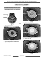
DISC REPLACEMENT
DISC REPLACEMENT WS-40/80
1.
Remove screws and cap cover from level one.
Fig. 21
4.
Remove meter drive pawl.
Fig. 19
2.
Remove balance piston.
Fig. 22
5.
Remove meter disc.
Fig. 20
3.
Remove balance piston o-ring and balance
piston spring.
Fig. 23
F25404 Rev. A (0413)
Page 8 of 10
WS-40/80 Hobart Compact Water Softener Installation Instructions - DISC REPLACEMENT
6.
Install correct meter disc and reassemble in
reverse order.
NOTE: Be certain to start cap screws by hand rotating
backwards until screw drops into thread then tighten.
An alternating, crossing pattern should be used while
tightening cap screws to ensure correct cap fit.
Page 9 of 10
F25404 Rev. A (0413)
WS-40/80 Hobart Compact Water Softener Installation Instructions - DISC SELECTION
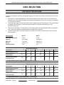
DISC SELECTION
DISC SELECTION WS-40/80
The amount of hardness removed (in compensated gpg) will be based on the amount of brine and the meter disc
selected.
1.
Determine the compensated hardness. This requires a hardness test and an iron test on raw water at the
application site. Compensated hardness is calculated by multiplying the ferrous iron (in ppm) by 3 and adding
it to the grains of hardness.
2.
To test the water supply, use the water analysis test kit available through Pro Products Inc. The recommended
kit is #2401 Field Analysis Kit. To order the test kit contact Pro Products at 800-285-9176 or visit
www.ProProducts.com.
3.
Determine the salt setting. The salt setting is determined by taking the compensated hardness (calculated in
step 1 above) and using the specification table for model WS-40 or WS-80.
4.
Verify the float cup setting. Use specifications for the WS-40 or WS-80 to determine the correct setting the
float cup height.
Specifications
WS-40
WS-80
Salt usage / generation
1.0 lbs.
1.4 lbs.
Capacity
2,527 grains
4,818 grains
Efficiency
2,527 gr./lb.
3,442 gr./lb.
Dosing
5.5 lbs./cu. ft.
3.5 lbs./cu. ft.
Float cup setting
6.25"
6.5"
WS-40 Disc Selection *
Disc Number
1
2
3
4
5
6
7
8
Compensated Hardness *
4
8
11
15
19
23
27
30
Gallons Between
Regeneration
9.1
9.1
9.1
9.1
8.4
6.6
5.4
4.4
583
282
194
146
117
97
83
73
Rregeneration Gallons
(min.) @ 15 psig
* Compensated hardness in gpg = Hardness + (3 x Fe in mg/l)
WS-80 Disc Selection *
Disc Number
1
2
3
4
5
6
7
8
Compensated Hardness *
5
11
17
22
27
32
35
40
Gallons Between
Regeneration
10.2
10.2
10.2
10.2
10.2
8.3
6.7
5.5
732
366
244
183
146
122
105
92
Rregeneration Gallons
(min.) @ 15 psig
* Compensated hardness in gpg = Hardness + (3 x Fe in mg/l)
F25404 Rev. A (0413)
Page 10 of 10