1
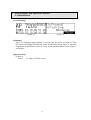
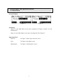
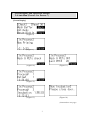
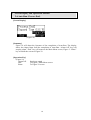
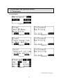
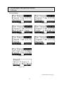
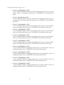
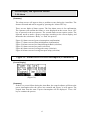
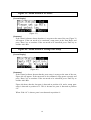
TM
AP 720S
LCD Panel Guide
OPTIGEN®
Semi-Automated Instrument
Confidentiality Notice
The materials and information contained herein are being provided by Hitachi Chemical
Diagnostics to its customer solely for customer’s use for its internal business purposes.
Hitachi Chemical Diagnostics retains all rights, title, interest in and copyrights to the
materials and information herein. The materials and information contained herein
constitute confidential information of Hitachi Chemical Diagnostics and customer shall
not disclose or transfer any of these materials or information to any third party.
Copyright © 2007
Hitachi Chemical Diagnostics, Inc.
630 Clyde Court
Mountain View, California 94043
_________________
U.S. and Foreign Patents Pending
All rights reserved. No part of this book may be reproduced in any form without written
permission from Hitachi Chemical Diagnostics, Inc.
Document Number: 0781 Revision: 01
Date: November 2007
1
―
Table of Contents
―
1
Operation Key…………………………………………………………...
Page
3
2
Screen Display and Operation Method
2-1
Initialization………………………………………………………
2-2
Main Menu……………………………………………………….
2-3
Panel Type Selection……………………………………………..
4
5
6
2-4
Auto-Run (Process 1 to 7)……………………………………….
2-5
Auto-Run (Photoreagent Setup and Process 8)………………….
2-6 Auto-Run (Process End)…………………………………………
2-7
Maintenance……………………………………………………...
2-8 Pause……………………………………………………………..
2-9
Start/End Process and Position Setup…………………………….
2-10 Alarm……………………………………………………………..
7
9
10
11
13
16
17
Flowchart………………………………………………………………...
21
3
2
1
Operation Key
Display:
Liquid Crystal Panel
Operation Key:
Only the touch panel key in the shaded field is executable. Press the Operation Key
to execute the function. See Figure 1.
Numerical Value Input Key:
Numerical value can be registered by ‘ENT’ key. If the value entered is out of the
defined range, beep sounds will be on for 3 times. ‘ESC’ key is used for returning
to the original value. See Figure 2.
(Figure 1)
(Figure 2)
3
2 Screen Display and Operation Method
2-1 Initialization
[Screen Display]
(Figure 3)
(Figure 4)
[Summary]
Figure 3 will display approximately 5 seconds after the power is turned on. Then
the screen will change automatically to the initialization screen, Figure 4. After the
completion of initialization, there is a beep sound and Main Menu screen, Figure 5
will display.
[Operation Key]
(Figure 4)
Pause:
To Figure 27 Pause screen
4
2 Screen Display and Operation Method
2-2 Main Menu
[Screen Display]
(Figure 5)
(Figure 6)
[Summary]
Figure 5 is the Main Menu screen after completion of Figure 4. Panel 36 is the
default panel.
Figure 6 is the Main Menu screen after selecting Panel 20 in Figure 7.
[Operation Key]
Panel 36:
To Figure 7 Panel Type Selection screen
Next:
To Figure 8 Auto-Run screen
Maintenance:
To Figure 19 Maintenance screen
5
2 Screen Display and Operation Method
2-3 Panel Type Selection
[Screen Display]
(Figure 7)
[Summary]
Select 36-allergen or 20-allergen panel in Figure 7.
[Operation Key]
36:
To Figure 5 Main Menu screen
20:
To Figure 6 Main Menu screen
6
2 Screen Display and Operation Method
2-4 Auto-Run (Process 1 to Process 7)
[Screen Display]
(Figure 8)
(Figure 9)
(Figure 10)
(Figure 11)
(Figure 12)
(Figure 13)
(Figure 14)
(Continued on next page)
7
(Auto-Run, cont.)
[Summary]
Figure 8 is a confirmation screen. The Operator needs to check that the Wash
Buffer Bottle and Antibody Reservoir are filled, and that the Waste Bottle is
emptied prior to the Auto-Run. Press “Start” key. The following screens will be
displayed in order and Auto-Run will be executed:
o Figure 9 displays the priming is in process.
o Figure 10 displays the Rack and Pette setup is being checked.
o Figure 11 displays the Rack and Pette setup is confirmed.
o Figure 12 displays the washing process (Process 1, 4 or 7) or aspiration
process (Process 2 or 5) is in operation. See Chapter 6, Operation, in the AP
720S Instruction Manual.
o Figure 13 shows incubation process (Process 3 or 6) is in operation.
o Figure 14 is a warning screen during incubation. It indicates the door is open
with a beep sound. After the door is closed, the screen will return to Figure 13.
In the case the door is open during the operation, i.e. initialization, priming,
rack & pettes check, washing, aspirating, rinsing and draining, the screen will
switch to Pause (see section 2-8 Pause)
[Operation Key]
(Figure 8)
Start: To Figure 9 Priming screen
Back: To Figure 5 Main Menu screen
(Figure 9)
Pause: To Figure 28 Pause screen
(Figure 10)
Pause: To: Figure 29 Pause screen
(Figure 11)
Pause: To: Figure 29 Pause screen
(Figure 12)
Pause: To: Figure 30 Pause screen
8
2 Screen Display and Operation Method
2-5 Auto-Run (Photoreagent Setup and Process 8)
[Screen Display]
(Figure 15)
(Figure 16)
(Figure 17)
[Summary]
Figure 15 will alarm Operator that Photoreagent is needed. The display shows the
elapsed time from the start of auto-pause. “Alarm Off” key will stop the alarm.
“Continue” key will shift the screen to Figure 16.
Figure 16 requests confirmation of Photoreagent setup. “No” key will return to the
previous screen. “Yes” key will shift the screen to Figure 17 and continue
Auto-Run. Please note that before pressing “Yes” key, the Operator needs to fill the
Photoreagent Reservoir with Photoreagent mixture and load into Sample/Reagent
Rack. See instructions in AP 720S Instruction Manual.
[Operation Key]
(Figure 15)
Alarm Off:
Continue:
Stop beep sound
To Figure 16 screen
(Figure 16)
Yes:
No:
To Figure 17 screen
To Figure 15 screen
(Figure 17)
Pause:
To Figure 30 Pause screen
9
2 Screen Display and Operation Method
2-6 Auto-Run (Process End)
[Screen Display]
(Figure 18)
[Summary]
Figure 18 will alarm the Operator of the completion of Auto-Run. The display
shows the elapsed time from the completion of Auto-Run. “Alarm Off” key will
stop the alarm. “End” key will return to the Main Menu screen, Figure 5. “Rinse”
key will shift the screen to Figure 22.
[Operation Key]
(Figure 18)
Alarm Off:
End:
Rinse:
Stop beep sound
To Figure 5 Main Menu screen
To Figure 22 screen
10
2 Screen Display and Operation Method
2-7 Maintenance
[Screen Display]
(Figure 19)
(Figure 20)
(Figure 21)
(Figure 22)
(Figure 23)
(Figure 24)
(Figure 25)
(Figure 26)
(Continued on next page)
11
(Maintenance, cont.)
[Summary]
Figure 19 provides the Prime, Rinse and Clock functions.
[Operation Key]
(Figure 19)
Prime: To Figure 20 Prime Operation screen
Rinse: To Figure 22 Rinse Operation screen
Clock: To Figure 26 Time Setup screen
Back: To Figure 5 Main Menu screen
(Figure 20)
Prior to Prime Operation, the Operator needs to set the Wash Buffer tube into
the Wash Buffer Bottle, the water tube into the Deionized Water Bottle, &
empty the Waste Bottle. “Ok” key will start priming operation.
Ok: To Figure 21 Priming Operation screen
Back: To Figure 19 Maintenance screen
(Figure 22)
Prior to Rinse Operation, the Operator needs to set the Wash Buffer tube and
water tube into Deionized Water Bottle. “Ok” key will start rinsing operation.
Ok: To Figure 23 Rinse Operation screen
Back: To Figure 19 Maintenance screen
(Figure 24)
Prior to Drain Operation, the Operator needs to pull out the tubes from Wash
Buffer Bottle and Deionized Water Bottle. “Ok” key will start draining
operation.
Ok: To Figure 25 Drain Operation screen
End: To Figure 19 Maintenance screen
(Figure 26)
Internal clock of the machine can be set in this screen.
Year: Figure 2 numerical value input screen with title [#Years]
Month: Figure 2 numerical value input screen with title [#Months]
Day: Figure 2 numerical value input screen with title [#Days]
Hour: Figure 2 numerical value input screen with title [#Hours]
Minute: Figure 2 numerical value input screen with title [#Minutes]
Second: Figure 2 numerical value input screen with title [#Seconds]
Set: Clock is set, return to Figure 19 Maintenance screen
Back: Clock is not set, return to Figure 19 Maintenance screen
12
2 Screen Display and Operation Method
2-8 Pause
[Screen Display]
(Figure 27)
(Figure 28)
(Figure 29)
(Figure 30)
(Figure 31)
(Figure 32)
(Figure 33)
(Figure 34)
(Continued on next page)
13
(Pause, cont.)
[Summary]
Figure 27 to Figure 33 the alarm will indicate that the current operation is paused.
The screen will display the [Run Status] including the time elapsed from the start
of the pause. A message “Information=” may be displayed in the screen, Figure 33.
See [Supplement] below for details.
“Continue” key will shift the screen to the original status, and resume the operation.
For example, in Figure 30 Process was paused at pette #12 and the operation will
resume on pette #12. “Cancel” key will shift the screen to Figure 34. “No” key
will return to the previous screen. “Yes” key will forward to Figure 3.
[Operation Key]
(Figure 27) to (Figure 33)
Alarm Off:
Stop beep sound
Continue:
Return to the original screen and operation is resumed
Cancel:
To Figure 34
(Figure 34)
Yes:
No:
To Figure 3
To previous screen
[Supplement]
At the time of operation failure, the instrument will automatically pause and
various warning message will be displayed on the screen. Even though operation
can resume, if causes of failure remain, the instrument will pause again. Please call
Service Representative for additional assistance.
The following are examples of alarm messages:
o Example) “Information=D. Open”
“D. Open” indicates that the door is open after the start of run operation. Press
“CONTINUE” key after the door is closed.
o Example) “Information =C1 L”
“C1 L” indicates failure from both sides of head part of carrier drive or sensor
failure. After you confirm the status, press “CONTINUE” key and check the
status.
o Example) “Information =C1 H”
“C1 H” indicates failure from both sides of head part of carrier drive or sensor
failure. After you confirm the status, press “CONTINUE” key and check the
status.
(Continued on next page)
14
(Examples of alarm messages, cont.)
o Example) “Information =C2 L”
“C2 L” indicates failure from the head part of top/bottom carrier drive or sensor
failure. After you confirm the status, press “CONTINUE” key and check the
status.
o
Example) “Information =C2 H”
“C2 H” indicates failure from the head part of top/bottom carrier drive or
sensor failure. After you confirm the status, press “CONTINUE” key and check
the status.
o Example) “Information =C3 L”
“C3 L” indicates failure of PET rack rotation carrier drive or sensor failure.
After you confirm the status, press “CONTINUE” key and check the status.
o Example) “Information =C3 H”
“C3 H” indicates failure of PET rack rotation carrier drive or sensor failure.
After you confirm the status, press “CONTINUE” key and check the status.
o Example) “Information =C4 L”
“C4 L” indicates failure of reagent rack rotation carrier drive or sensor failure.
After you confirm the status, press “CONTINUE” key and check the status.
o Example) “Information =C4 H”
“C4 H” indicates failure of reagent rack rotation carrier drive or sensor failure.
After you confirm the status, press “CONTINUE” key and check the status.
o Example) “Information =C5 L”
“C5 L” indicates failure of aspiration syringe drive or sensor failure. After you
confirm the status, press “CONTINUE” key and check the status.
o Example) “Information =C5 H”
“C5 H” indicates failure of aspiration syringe drive or sensor failure. After you
confirm the status, press “CONTINUE” key and check the status.
o Example) “Information =C6 L”
“C6 L” indicates failure of wash syringe drive or sensor failure. After you
confirm the status, press “CONTINUE” key and check the status.
o Example) “Information =C6 H”
“C6 H” indicates failure of wash syringe drive or sensor failure. After you
confirm the status, press “CONTINUE” key and check the status.
15
2 Screen Display and Operation Method
2-9 Start/End Process and Position Setup
[Screen Display]
(Figure 35)
Start
Process
End
Process
[Summary]
Figure 35 will appear when power interruption occurs during Auto-Run or the
current process is cancelled/paused during Auto-Run.
Before re-starting the Auto-Run, the Operator needs to setup the START
PROCESS NO., END PROCESS NO. and PETTE POSITION NO. according to
the status at the interruption of Auto-Run so that the operation will be continued
without missing steps.
Start Process:
End Process:
Position:
Range 1-8 (a smaller number than End Process)
Range 1-8 (a greater number than Start Process)
Pette start position, range 1-20
[Operation Key]
(Figure 35)
Start Process key:
To Figure 2 numerical value input screen with the
title [Start Process]
End Process key:
To Figure 2 numerical value input screen with the
title [End Process]
Start Position key:
To Figure 2 numerical value input screen with the
title [Start Position]
Next:
To Figure 8 Auto-Run screen
Back:
To Figure 5 Main Menu screen
16
2 Screen Display and Operation Method
2-10 Alarm
[Summary]
The alarm screen will appear when a problem occurs during the Auto-Run. The
alarm will sound and can be stopped by pressing the “Alarm Off” key.
There are two kinds of alarm screens. The first alarm screen is for confirmation.
The Operator will confirm the failure or error displayed on the screen. Press “Ok”
key to proceed to the next process. The second alarm screen requires action. The
Operator needs to make a proper correction according to the screen display, and
then make the selection to “Retry” or “End” the process.
Figure 36 Alarm screen of power interruption (confirmation)
Figure 37 Alarm screen of data initialization (confirmation)
Figure 38 Alarm screen of no Sample/Reagent Rack (selection)
Figure 39 Alarm screen of no pettes (selection)
Figure 40 Alarm screen of wrong pette setup (selection)
Figure 41 Alarm screen of wrong start pette setup (selection)
Figure 36 - Alarm Screen of Power Interruption (Confirmation)
[Screen Display]
(Figure 36)
[Summary]
If there is a power failure during the Auto-Run, the control software will detect the
power interruption after the power has returned and Figure 36 will appear. The
elapsed time from the start of power interruption will be displayed. Press ‘Ok’
key to continue the process.
17
Figure 37 - Alarm Screen of Data Initialization (Confirmation)
[Screen Display]
(Figure 37)
[Summary]
Figure 37 shows data error has occurred after initialization. The Operator needs to
press “Ok” so that the data for the instrument will be recovered and the default
values will be implemented. Re-entry of program and internal parameters may be
required. If this is the case, please contact your Service Representative.
Figure 38 - Alarm Screen of No Sample/Reagent Rack
[Screen Display]
(Figure 38)
[Summary]
If the control software detects that there is no Sample/Reagent Rack at the start of
the run, Figure 38 will appear. If the run needs to be continued, setup the
Sample/Reagent Rack, and press ‘Retry’ to continue. If the run needs to be
cancelled, press ‘End’ key to end the Auto-Run.
18
Figure 39 - Alarm Screen of No Pettes
[Screen Display]
(Figure 39)
[Summary]
If the control software detects that there is no pette at the start of the run, Figure 39
will appear. If the run needs to be continued, setup pettes in the Pette Rack, and
press ‘Retry’ key to continue. If the run needs to be cancelled, press ‘End’ key to
end the Auto-Run.
Figure 40 - Alarm Screen of Wrong Pette Setup
[Screen Display]
(Figure 40)
[Summary]
If the control software detects that the pette setup is wrong at the start of the run,
Figure 40 will appear. If the run needs to be continued, setup pettes correctly and
press ‘Retry’ key to continue. If the run needs to be cancelled, press ‘End’ key to
end the Auto-Run.
Figure 40 shows that the last pette is detected at position #10, and a wrong pette
setup is detected at position #12. This is because no pette is detected at position
#11.
When “End # 0” is shown, pette is not detected at position #1.
19
Figure 41 - Alarm Screen of Wrong Start Pette Setup
[Screen Display]
(Figure 41)
[Summary]
If the control software detects that the position of the start pette is wrong at the
start of the run, Figure 41 will appear. If the run needs to be continued, setup the
pettes correctly, press ‘Retry’ key to continue. If the run needs to be cancelled,
press ‘End’ key to end the Auto-Run.
Figure 41 shows that the pettes are loaded from position #1 to #4. However, the
Operator entered position #6 for the pette start position (refer to section 2-9).
Figure 42 - Alarm Screen of Communication Error
[Screen Display]
(Figure 42)
[Summary]
After the power is turned on, Figure 42 will appear if the control software cannot
communicate with the panel operation. The version information and current
date/time will not be displayed in the screen as Figure 3 shows. The date/time
display will count up from 80/1/10:0:0.
When this alarm screen occurs, normal machine function is not possible.
Please contact your Service Representative.
20
AP720S™ Panel Flowchart
Auto-Run
Pause
Maintenance
Interrupted run
21