1
Projector
CP-X8150/CP-X8160/
CP-WX8240/CP-WX8255/
CP-SX8350/CP-WU8440/CP-WU8450
User's Manual (detailed)
Operating Guide – Technical
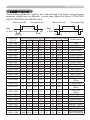
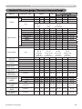
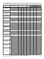
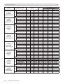
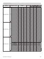
Example of computer signal
Resolution (H x V) H. frequency (kHz) V. frequency (Hz)
Rating
Signal mode
37.9
31.5
37.9
37.5
43.3
35.2
37.9
48.1
46.9
53.7
49.7
48.4
56.5
60.0
68.7
67.5
47.7
49.7
60.0
64.0
80.0
55.9
VESA
VESA
VESA
VESA
VESA
VESA
VESA
VESA
VESA
VESA
TEXT
VGA (60Hz)
VGA (72Hz)
VGA (75Hz)
VGA (85Hz)
SVGA (56Hz)
SVGA (60Hz)
SVGA (72Hz)
SVGA (75Hz)
SVGA (85Hz)
Mac 16” mode
XGA (60Hz)
XGA (70Hz)
XGA (75Hz)
XGA (85Hz)
1152 x 864 (75Hz)
W-XGA (60Hz)
1280 x 800 (60Hz)
1280 x 960 (60Hz)
SXGA (60Hz)
SXGA (75Hz)
WXGA+ (60Hz)
720 x 400
640 x 480
640 x 480
640 x 480
640 x 480
800 x 600
800 x 600
800 x 600
800 x 600
800 x 600
832 x 624
1024 x 768
1024 x 768
1024 x 768
1024 x 768
1152 x 864
1280 x 768
1280 x 800
1280 x 960
1280 x 1024
1280 x 1024
1440 x 900
85.0
59.9
72.8
75.0
85.0
56.3
60.3
72.2
75.0
85.1
74.5
60.0
70.1
75.0
85.0
75.0
60.0
60.0
60.0
60.0
75.0
59.9
VESA
VESA
VESA
VESA
VESA
VESA
VESA
VESA
VESA
VESA
VESA
(continued on next page)
1
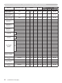
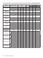
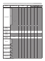
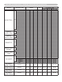
Example of computer signal
Resolution (H x V)
H. frequency (kHz)
V. frequency (Hz)
Rating
Signal mode
1280 x 1024
1400 x 1050
1680 x 1050
1600 x 1200
91.1
65.2
65.3
75.0
85.0
60.0
60.0
60.0
VESA
VESA
VESA
VESA
*4 1920 x 1200
74.0
60.0
VESA
SXGA (85Hz)
SXGA+ (60Hz)
WSXGA+ (60Hz)
UXGA (60Hz)
W-UXGA (60Hz)
Reduced Blanking
*1
*2
*3
*1
*1) Supported except for HDMI input.
*2) Only for CP-X8150, CP-X8160 and CP-SX8350.
*3) Only for CP-WX8240, CP-WX8255, CP-WU8440 and CP-WU8450.
*4) Only for CP-WU8440 and CP-WU8450, but except for HDMITM input.
TM
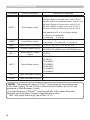
NOTE • Be sure to check jack type, signal level, timing and resolution
before connecting this projector to a computer.
• Some computers may have multiple display screen modes. Use of some of
these modes will not be possible with this projector.
• Depending on the input signal, full-size display may not be possible in some
cases. Refer to the number of display pixels above.
• Although the projector can display signals with resolution up to UXGA
(1600x1200) or with W-UXGA only for CP-WU8440 and CP-WU8450, the
signal will be converted to the projector’s panel resolution before being
displayed. The best display performance will be achieved if the resolutions of
the input signal and projector panel are identical.
• Automatic adjustment may not function correctly with some input signals.
• The image may not be displayed correctly when the input sync signal is a
composite sync or a sync on G.
2
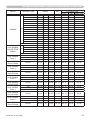
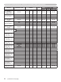
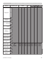
Initial set signals
Initial set signals
The following signals are used for the initial settings. The signal timing of some
computer models may be different. In such case, adjust the items V POSITION
and H POSITION in the IMAGE menu.
Back porch (B)
Front porch (D)
Active video (C)
Data
H. Sync.
Back porch (b)
Resolution
(H x V)
720 x 400
640 x 480
640 x 480
640 x 480
640 x 480
800 x 600
800 x 600
800 x 600
800 x 600
800 x 600
832 x 624
1024 x 768
1024 x 768
1024 x 768
1024 x 768
Active video (c)
Data
V. Sync.
Sync (A)
Sync (a)
Horizontal signal timing (μs) Vertical signal timing (lines)
(A)
(B)
(C)
(D)
(a)
(b)
(c)
(d)
2.0
3.0 20.3 1.0
3
42
400
1
3.8
1.9 25.4 0.6
2
33
480
10
1.3
4.1 20.3 0.8
3
28
480
9
2.0
3.8 20.3 0.5
3
16
480
1
1.6
2.2 17.8 1.6
3
25
480
1
2.0
3.6 22.2 0.7
2
22
600
1
3.2
2.2 20.0 1.0
4
23
600
1
2.4
1.3 16.0 1.1
6
23
600
37
1.6
3.2 16.2 0.3
3
21
600
1
1.1
2.7 14.2 0.6
3
27
600
1
1.1
3.9 14.5 0.6
3
39
624
1
2.1
2.5 15.8 0.4
6
29
768
3
1.8
1.9 13.7 0.3
6
29
768
3
1.2
2.2 13.0 0.2
3
28
768
1
1.0
2.2 10.8 0.5
3
36
768
1
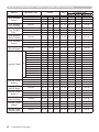
1152 x 864
1.2
2.4
10.7
0.6
3
32
864
1
1280 x 768
1.7
2.5
16.0
0.8
3
23
768
1
1280 x 800
1.6
2.4
15.3
0.8
3
24
800
1
1280 x 960
1.0
2.9
11.9
0.9
3
36
960
1
1280 x 1024
1280 x 1024
1280 x 1024
1400 x 1050
1440 x 900
1680 x 1050
1600 x 1200
1.0
1.1
1.0
1.2
1.4
1.2
1.2
2.3
1.8
1.4
2.0
2.2
1.9
1.9
11.9
9.5
8.1
11.4
13.5
11.5
9.9
0.4
0.1
0.4
0.7
0.8
0.7
0.4
3
3
3
3
6
6
3
38
38
44
33
25
30
46
1024
1024
1024
1050
900
1050
1200
1
1
1
1
3
3
1
6
26
1200
3
1920 x 1200
Front porch (d)
0.208 0.519 12.47 0.312
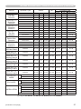
Signal mode
TEXT
VGA (60Hz)
VGA (72Hz)
VGA (75Hz)
VGA (85Hz)
SVGA (56Hz)
SVGA (60Hz)
SVGA (72Hz)
SVGA (75Hz)
SVGA (85Hz)
Mac 16" mode
XGA (60Hz)
XGA (70Hz)
XGA (75Hz)
XGA (85Hz)
1152 x 864
(75Hz)
W-XGA (60Hz)
1280 x 800
(60Hz)
1280 x 960
(60Hz)
SXGA (60Hz)
SXGA (75Hz)
SXGA (85Hz)
SXGA+ (60Hz)
WXGA+ (60Hz)
WSXGA+ (60Hz)
UXGA (60Hz)
W-UXGA (60Hz)
Reduced Blanking
3
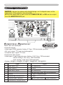
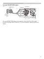
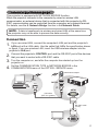
Connection to the ports
Connection to the ports
NOTICE ►Use the cables with straight plugs, not L-shaped ones, as the
input ports of the projector are recessed.
►Only the signal that is input from the COMPUTER IN1 or IN2 can be output
from the MONITOR OUT port.
A
B
A COMPUTER IN1, B MONITOR OUT
⑪⑫⑬⑭⑮
⑥⑦⑧⑨⑩
①②③④⑤
D-sub 15pin mini shrink jack
<Computer signal>
• Video signal: RGB separate, Analog, 0.7Vp-p, 75Ω terminated (positive)
• H/V. sync. signal: TTL level (positive/negative)
• Composite sync. signal: TTL level
<Component video signal>
• Video signal: Y with composite sync, Analog, 1.0±0.1Vp-p, 75Ω terminated
Cb/Pb, Analog, 0.7±0.1Vp-p, 75Ω terminated
Cr/Pr, Analog, 0.7±0.1Vp-p 75Ω terminated
• System: 480i@60, 480p@60, 576i@50, 720p@50/60, 1080i@50/60
Pin
4
Signal
Pin
Signal
1
Video Red, Cr/Pr
9
(No connection)
2
Video Green, Y
10
Ground
3
Video Blue, Cb/Pb
11
(No connection)
4
(No connection)
12
A : SDA (DDC data) B : (No connection)
5
Ground
13
H. sync / Composite sync.
6
Ground Red, Ground Cr/Pr
14
V. sync.
7
Ground Green, Ground Y
15
A : SCL (DDC clock) B : (No connection)
8
Ground Blue, Ground Cb/Pb
⑤
⑮
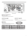
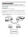
Connection to the ports (continued)
H
I
C
D
F
E
G
COMPUTER IN2 C G/Y, D B/Cb/Pb, E R/Cr/Pr, F H, G V
BNC jack x5
<Computer signal>
• Video signal: RGB separate, Analog, 0.7Vp-p, 75Ω terminated (positive)
• H/V. sync. signal: TTL level (positive/negative)
• Composite sync. signal: TTL level
<Component video signal>
• Video signal: Y with composite sync, Analog, 1.0±0.1Vp-p, 75Ω terminated
Cb/Pb, Analog, 0.7±0.1Vp-p, 75Ω terminated
Cr/Pr, Analog, 0.7±0.1Vp-p 75Ω terminated
• System: 480i@60, 480p@60, 576i@50, 720p@50/60, 1080i@50/60
H HDMI 1, I HDMI 2
HDMITM connector
• Audio signal: Linear PCM (Sampling rate; 32/44.1/48 kHz)
Pin
Signal
Pin
Signal
②④⑥⑧⑩⑫⑭⑯⑱
⑲⑰⑮⑬
①③⑤⑦⑨⑪⑬⑮⑰⑲
⑱⑯⑭
Pin
Signal
1
T.M.D.S. Data2 +
8
T.M.D.S. Data0 Shield
15 SCL
2
T.M.D.S. Data2 Shield
9
T.M.D.S. Data0 -
16 SDA
3
T.M.D.S. Data2 -
10 T.M.D.S. Clock +
17 DDC/CEC Ground
4
T.M.D.S. Data1 +
11 T.M.D.S. Clock Shield
18 +5V Power
19 Hot Plug Detect
5
T.M.D.S. Data1 Shield
12 T.M.D.S. Clock -
6
T.M.D.S. Data1 -
13 CEC
7
T.M.D.S. Data0 +
14 Reserved (N.C. on device)
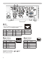
5
Connection to the ports (continued)
N
M
L
K
J
COMPONENT J Y, K Cb/Pb, L Cr/Pr
RCA jack x3
①
③
• Component video signal, Analog:
-Y with composite sync, 1.0±0.1Vp-p, 75Ω terminated
-Cb/Pb, 0.7±0.1Vp-p, 75Ω terminated
-Cr/Pr, 0.7±0.1Vp-p 75Ω terminated
• System: 480i@60, 480p@60, 576i@50, 720p@50/60, 1080i@50/60, 1080p@50/60
②
④
2 4
④
②
M S-VIDEO
1 3
③
①
Mini DIN 4pin jack
• S-video signal, Analog:
-Brightness signal with composite sync, 1.0±0.1Vp-p, 75Ω terminated
-Color signal, 0.286Vp-p (NTSC, burst), 75Ω terminated
0.300Vp-p (PAL/SECAM, burst) 75Ω terminated
• System: NTSC, PAL, SECAM, PAL-M, PAL-N, NTSC4.43, PAL(60Hz)
Pin
Signal
1
C (color signal)
2
Y (brightness signal)
3
Ground
4
Ground
N VIDEO
RCA jack
• Composite video signal, Analog, 1.0±0.1Vp-p, 75Ω terminator
• System: NTSC, PAL, SECAM, PAL-M, PAL-N, NTSC4.43, PAL(60Hz)
6
Connection to the ports (continued)
U
S
Q
T
R
O
P
O AUDIO IN1, P AUDIO IN2
Ø3.5 stereo mini jack
• Analog, 500 mVrms, 47kΩ input impedance
AUDIO IN3 Q L, R R
AUDIO OUT S L, T R
RCA jack x2
RCA jack x2
• Analog, 500 mVrms, 47kΩ input impedance
• Analog, 500 mVrms, 1kΩ output impedance
U CONTROL
D-sub 9pin plug
① ② ③ ④ ⑤
⑨ ⑧ ⑦ ⑥
⑥ ⑦ ⑧ ⑨
⑤ ④ ③ ② ①
* About the details of RS-232C communication,
please refer to the next section.
Pin
Signal
Pin
Signal
Pin
Signal
1
(No connection)
4
(No connection)
7
RTS
2
RD
5
Ground
8
CTS
3
TD
6
(No connection)
9
(No connection)
7
Connection to the ports (continued)
X
W
V
Y
Z
V LAN
RJ-45 jack
Pin
1
Signal
TX+
Pin
4
Signal
-
8
-
TX-
5
-
RX+
6
RX-
W USB TYPE A
Pin
Signal
④ ③② ①
④ ③② ①
X USB TYPE B
USB B type jack
Pin
① ②③ ④
Signal
+5V
1
+5V
2
- Data
2
- Data
3
+ Data
3
+ Data
4
Ground
4
Ground
Ø3.5 stereo mini jack
④③
②①
①②
③④
① ②③ ④
1
REMOTE CONTROL Y IN, Z OUT
8
Signal
7
2
USB A type jack x2
Pin
-
3
⑧ ⑥ ④ ②
⑦ ⑤ ③ ①
② ④ ⑥ ⑧
① ③ ⑤ ⑦
* About the details of network communication,
please refer to the Network Guide.
Connection to the ports (continued)
To input SCART RGB signal;
ex.
SCART cable
(plug)
Audio L
RCA plugs
Audio R
Video
R
SCART
connector
(jack)
B
G
To input SCART RGB signal to the projector, use a SCART to RCA cable.
Connect the plugs refer to above ex. For more reference, please consult your
dealer.
9
RS-232C Communication
RS-232C Communication
When the projector connects to the computer by RS-232C communication, the
projector can be controlled with RS-232C commands from the computer.
For details of RS-232C commands, refer to RS-232C Communication / Network
command table (&19).
Connection
1. Turn off the projector and the computer.
the projector's CONTROL port and the computer's RS-232C port
2. Connect
with a RS-232C cable (cross). Use the cable that fulfills the specification
shown in figure
Turn the computer on, and after the computer has started up turn the projector
on.
Set the COMMUNICATION TYPE to OFF in the COMMUNICATION menu of the
OPTION - SERVICE menu.
3.
4.
RS-232C
CONTROL
RS-232C cable
(cross)
CONTROL port
of the projector
RS-232C port
of the computer
1
2
6
3
7
4
8
6
5
9
1
7
2
8
3
9
4
5
CD (1)
RD(2)
TD (3)
DTR (4)
GND (5)
DSR (6)
RTS (7)
DTS (8)
RI (9)
10
① ② ③ ④ ⑤
⑨ ⑧ ⑦ ⑥
⑥ ⑦ ⑧ ⑨
⑤ ④ ③ ② ①
(1) -
(2) RD
(3) TD
(4) -
(5) GND
(6) -
(7) RTS
(8) CTS
(9) -
RS-232C Communication (continued)
Communicaion settings
1. Protocol
19200bps, 8N1
2. Command format ("h" shows hexadecimal)
Byte Number
0
1
Command
Action
2
3
4
5
6
7
8
9
Header
Header
code Packet
L
H
10
11
12
Data
Data
size
CRC
flag
Action
Type
Setting
code
L
L
L
L
L
H
H
H
H
H
<SET>Change setting to
desired value [(cL)(cH)]
by [(bL)(bH)].
(aL) (aH) 01h 00h (bL) (bH) (cL) (cH)
<GET>Read projector
internal setup value [(bL)
(bH)] .
(aL) (aH) 02h 00h (bL) (bH) 00h
00h
(aL) (aH) 04h 00h (bL) (bH) 00h
00h
<DECREMENT>
Decrement setup value
[(bL)(bH)] by 1.
(aL) (aH) 05h 00h (bL) (bH) 00h
00h
<EXECUTE> Run a
command [(bL)(bH)].
(aL) (aH) 06h 00h (bL) (bH) 00h
00h
<INCREMENT>
Increment setup value
[(bL)(bH)] by 1.
BEh EFh
03h
06h 00h
[Header code] [Packet] [Data size]
Set [BEh, EFh, 03h, 06h, 00h] to byte number 0 to 4.
[CRC flag]
For byte number 5, 6, refer to RS-232C Communication / Network command
table (&19).
[Action]
Set functional code to byte number 7, 8.
<SET> = [01h, 00h], <GET> = [02h, 00h], <INCREMENT> = [04h, 00h]
<DECREMENT> = [05h, 00h], <EXECUTE> = [06h, 00h]
Refer to the Communication command table (&above).
[Type] [Setting code]
For byte number 9 to 12, refer to RS-232C Communication / Network
command table (&19).
11
RS-232C Communication (continued)
3. Response code / Error code ("h" shows hexadecimal)
(1) ACK reply: 06h
When the projector receives the Set, Increment, Decrement or Execute
command correctly, the projector changes the setting data for the specified
item by [Type], and it returns the code.
(2) NAK reply: 15h
When the projector cannot understand the received command, the projector
returns the error code.
In such a case, check the sending code and send the same command again.
(3) Error reply: 1Ch + 0000h
When the projector cannot execute the received command for any reasons,
the projector returns the error code.
In such a case, check the sending code and the setting status of the projector.
(4) Data reply: 1Dh + xxxxh
When the projector receives the GET command correctly, the projector returns
the responce code and 2 bytes of data.
NOTE • For connecting the projector to your devices, please read the
manual for each devices, and connect them correctly with suitable cables.
• Operation cannot be guaranteed when the projector receives an undefined
command or data.
• Provide an interval of at least 40ms between the response code and any
other code.
• The projector outputs test data when the power supply is switched ON, and
when the lamp is lit. Ignore this data.
• Commands are not accepted during warm-up.
• When the data length is greater than indicated by the data length code, the
projector ignore the excess data code. Conversely when the data length is
shorter than indicated by the data length code, the projector returns the error
code to the computer.
12
Command Control via the Network
Command Control via the Network
When the projector connects network, the projector can be controlled with RS232C commands from the computer with web browser.
For details of RS-232C commands, refer to RS-232C Communication / Network
command table (&19).
NOTE • If data is transferred via wireless and wired LAN at the same
time, the projector may not be able to process the data correctly.
Connection
Turn off the projector and the computer.
1.
If you use wired LAN, connect the projector's LAN port to the computer's
2. LAN port with a LAN cable. Use the cable that fulfills the specification shown
in figure. If you use wireless LAN, insert the USB wireless adapter into one of the
USB TYPE A ports of the projector.
Turn the computer on, and after the computer has started up turn the
projector on.
3.
USB wireless adapter
LAN
LAN cable (CAT-5 or greater)
13
Command Control via the Network
Communicaion Port
The following two ports are assigned for the command control.
TCP #23
TCP #9715
Configure the following items form a web browser when command control is used.
Port Settings
Network Control
Port1 (Port: 23)
Port open
Click the [Enable] check box to open [Network
Control Port1 (Port: 23)] to use TCP #23.
Default setting is “Enable”.
Authentication
Click the [Enable] check box for the
[Authentication] setting when authentication
is required.
Default setting is “Disable”.
Port open
Click the [Enable] check box to open [Network
Control Port2 (Port: 9715)] to use TCP
#9715.
Default setting is “Enable”.
Authentication
Click the [Enable] check box for the
[Authentication] setting when authentication
is required.
Default setting is “Enable”.
Network Control
Port2 (Port: 9715)
When the authentication setting is enabled, the following settings are required.
Security Settings
Authentication
Password
Network Control
14
Re-enter
Authentication
Password
Enter the desired authentication password.
ConfirmThis setting will be the same for
[Network Control Port1 (Port: 23)] and
[Network Control Port2 (Port: 9715)].
Default setting is blank.
Command Control via the Network (continued)
Command control settings
[TCP #23]
1. Command format
Same as RS-232C communication, refer to RS-232C Communicaton command format.
2. Response code / Error code ("h" shows hexadecimal)
Four of the response / error code used for TCP#23 are the same as RS-232C
Communication (1)~(4). One authentication error reply (5) is added.
(1) ACK reply : 06h
Refer to RS-232C communication (&12).
(2) NAK reply : 15h
Refer to RS-232C communication (&12).
(3) Error reply : 1Ch + 0000h
Refer to RS-232C communication (&12).
(4) Data reply : 1Dh + xxxxh
Refer to RS-232C communication (&12).
(5) Authentication error reply : 1Fh + 0400h
When authentication error occurred, the projector returns the error code.
[TCP #9715]
1. Command format
The commands some datum are added to the head and the end of the ones of
TCP#9715 are used.
Header
Data length
RS-232C command
Check sum
Connection ID
0×02
0×0D
13 bytes
1 byte
1 byte
[Header]
02, Fixed
[Data Length]
RS-232C commands byte length (0×0D, Fixed)
[RS-232C commands]
Refer to RS-232C Communication command format (&11).
[Check Sum]
This is the value to make zero on the addition of the lower 8 bits from the header
to the checksum.
[Connection ID]
Random value from 0 to 255 (This value is attached to the reply data).
NOTE • Operation cannot be guaranteed when the projector receives an
undefined command or data.
• Provide an interval of at least 40ms between the response code and any other
code.
• Commands are not accepted during warm-up.
15
Command Control via the Network (continued)
2. Response code / Error code ("h" shows hexadecimal)
The connection ID is attached for the TCP#23's response / error codes are
used. The connection ID is same as the sending command format.
(1) ACK reply: 06h + ××h
(××h : connection ID)
(2) NAK reply: 15h + ××h
(3) Error reply: 1Ch + 0000h + ××h
(4) Data reply: 1Dh + xxxxh + ××h
(5) Authentication error reply: 1Fh + 0400h + ××h
(6) Projector busy reply:
1Fh + ××××h + ××h
When the projector is too busy to receives the command ,the projector
returens the error code.
In such a case, check the sending code and send the same command again.
Automatic Connection Break
The TCP connection will be automatically disconnected after there is no
communication for 30 seconds after being established.
Authentication
The projector does not accept commands without authentication success
when authentication is enabled. The projector uses a challenge response type
authentication with an MD5 (Message Digest 5) algorithm.
When the projector is connected to a LAN, a random 8 bytes will be returned
if authentication is enabled. Bind this received 8 bytes and the authentication
password, and digest the data with the MD5 algorithm, and add it in front of the
commands to send.
Following is a sample of authentication process.
Authentication password: password (example)
Random 8 bytes: a572f60c (example)
1) Select a projector and receive the random 8 bytes from the projector.
“a572f60c”
2) Bind the random 8 bytes and the authentication password.
“a572f60cpassword”
3) Digest this bound with MD5 algorithm.
“e3d97429adffa11bce1f7275813d4bde”
4) Add this code in front of the commands and send the data.
“e3d97429adffa11bce1f7275813d4bde” + [command].
5) When the sent data is correct, the command will be performed and the reply
data will be returned. Otherwise, an authentication error will be returned.
NOTE • As for the transmission of the second or subsequent commands, the
authentication data can be omitted when the same connection.
16
Network Bridge Communication
Network Bridge Communication
This projector is equipped with NETWORK BRIDGE function.
When the projector connects to the computer by wired or wireles LAN
communicaton, an external device that is connected with this projector by RS232C communication can be controlled from the computer as a network terminal.
For details, see the 6. Network Bridge function in the Network Guide.
NOTE • If data is transferred via wireless and wired LAN at the same time,
the projector may not be able to process the data correctly.
Connection
If you use wired LAN, connect the computer's LAN port and the projector's
1. LAN port with a LAN cable. Use the cable that fulfills the specification shown
in figure. If you use wireless LAN, insert the USB wireless adapter into the
projector's LAN port.
Connect the projector's CONTROL port and the RS-232C port of the devices
that you want to control with a RS-232C cable.
Turn the computer on, and after the computer has started up turn the
projector on.
Set the COMMUNICATION TYPE to NETWORK BRIDGE in the
COMMUNICATION menu of the OPTION - SERVICE menu.
2.
3.
4.
USB wireless adapter
LAN
LAN cable
(CAT-5 or greater)
RS-232C cable
(cross)
RS-232C
17
Network Bridge Communication
Communication settings
For communication setting, use the COMMUNICATION menu in the OPTION SERVICE menu
Item
Condition
BAUD RATE
4800bps / 9600bps / 19200bps / 38400bps
Data length
8 bit (fixed)
PARITY
NONE/ODD/EVEN
Start bit
1 bit (fixed)
Stop bit
1 bit (fixed)
Transmission method
HALF-DUPLEX/FULL-DUPLEX
NOTE • For connecting the projector to your devices, please read the
manual for each devices, and connect them correctly with suitable cables.
• Turn off the power and unplug both the projector and other devices before
connecting them.
• For details of Transmission method, refer to 6.4 Transmission method in the
Network Guide.
18
RS-232C Communication / Network command table
RS-232C Communication / Network command table
Names
Operation Type
Set
Power
Input Source
Set
Error Status
FOCUS
ZOOM
LENS SHIFT - V
LENS SHIFT - H
LENS SHIFT
CENTERING
LENS MEMORY Set
INDEX
Header
Turn off
Turn on
BE EF
03
BE EF
03
BE EF
03
[Example return]
Get
00 00
[Off]
COMPUTER IN1 BE EF
03
COMPUTER IN2 BE EF
03
LAN
BE EF
03
USB TYPE A
BE EF
03
USB TYPE B
BE EF
03
HDMI 1
BE EF
03
HDMI 2
BE EF
03
COMPONENT
BE EF
03
S-VIDEO
BE EF
03
VIDEO
BE EF
03
Get
BE EF
03
BE EF
03
[Example return]
00 00
Get
[Normal]
04 00
[Temp error]
Increment
BE EF
03
Decrement
BE EF
03
Increment
BE EF
03
Decrement
BE EF
03
Increment
BE EF
03
Decrement
BE EF
03
Increment
BE EF
03
Decrement
BE EF
03
Execute
1
2
3
Get
CRC
Command Data
Action
Type
Setting code
01 00
01 00
02 00
00 60
00 60
00 60
00 00
01 00
00 00
00
00
00
00
00
00
00
00
00
00
00
20
00
04
0B
06
0C
03
0D
05
02
01
00
00
00
00
00
00
00
00
00
00
00
00
00
00
01 00
02 00
[Cover error]
[Fan error]
05 00
07 00
[Air flow error] [Cold error]
06 00
6A 93
04 00
06 00
BB 92
05 00
06 00
96 92
04 00
06 00
47 93
05 00
06 00
D2 92
04 00
06 00
03 93
05 00
06 00
2E 93
04 00
06 00
FF 92
05 00
03 00
[Lamp error]
08 00
[Filter error]
00 24
00
00 24
00
01 24
00
01 24
00
02 24
00
02 24
00
03 24
00
03 24
00
00
00
00
00
00
00
00
00
06 00
06 00
06 00
06
06
06
06
06
06
06
06
06
06
06
06
2A D3
BA D2
19 D3
01 00
[On]
00
FE
00
3E
00 CE
00
5E
00
FE
00
0E
00
6E
00 AE
00
9E
00
6E
00 CD
00
D9
02 00
[Cool down]
D2
01 00
D0
01 00
D5 01 00
D1
01 00
D7
01 00
D2
01 00
D6
01 00
D1 01 00
D3
01 00
D3
01 00
D2 02 00
D8
02 00
20
20
20
20
20
20
20
20
20
20
20
60
BE EF
03
06 00
B8 93
06 00
04 24
00 00
BE
BE
BE
BE
EF
EF
EF
EF
03
03
03
03
06
06
06
06
4B
DB
2B
78
01
01
01
02
07
07
07
07
00
01
02
00
00
00
00
00
92
93
93
92
00
00
00
00
24
24
24
24
00
00
00
00
LENS MEMORY
LOAD
Execute
BE EF
03
06 00
E8 90
06 00
08 24
00 00
LENS MEMORY
SAVE
Execute
BE EF
03
06 00
14 91
06 00
09 24
00 00
LENS MEMORY
CLEAR
Execute
BE EF
03
06 00
50 91
06 00
0A 24
00 00
(continued on next page)
19
RS-232C Communication / Network command table (continued)
Names
Operation Type
LENS MEMORY
LENS SHIFT - V
Get
BE EF
03
06 00
LENS MEMORY
LENS SHIFT - H
Get
BE EF
03
LENS MEMORY
LENS TYPE
Get
BE EF
BE
BE
BE
BE
BE
BE
BE
BE
BE
BE
BE
BE
BE
BE
BE
BE
BE
BE
BE
BE
BE
BE
BE
BE
BE
BE
BE
MAGNIFY
MAGNIFY
Position H
MAGNIFY
Position V
FREEZE
SHADE
PICTURE
MODE
BRIGHTNESS
Set
Set
Set
Get
Increment
Decrement
Get
Increment
Decrement
Get
Increment
Decrement
NORMAL
FREEZE
Get
OFF
ON
Get
NORMAL
CINEMA
DYNAMIC
BOARD(BLACK)
BOARD(GREEN)
WHITEBOARD
DAYTIME
DICOM SIM.
Get
Get
Increment
Decrement
Header
CRC
Command Data
Action
Type
Setting code
A0 91
02 00
0D 24
00 00
06 00
E4 91
02 00
0E 24
00 00
03
06 00
18 90
02 00
0F 24
00 00
EF
EF
EF
EF
EF
EF
EF
EF
EF
EF
EF
EF
EF
EF
EF
EF
EF
EF
EF
EF
EF
EF
EF
EF
EF
EF
EF
03
03
03
03
03
03
03
03
03
03
03
03
03
03
03
03
03
03
03
03
03
03
03
03
03
03
03
06
06
06
06
06
06
06
06
06
06
06
06
06
06
06
06
06
06
06
06
06
06
06
06
06
06
06
7C
1A
CB
C8
AE
7F
34
52
83
83
13
B0
F3
63
C0
23
B3
E3
E3
73
83
E3
73
10
89
EF
3E
02
04
05
02
04
05
02
04
05
01
01
02
01
01
02
01
01
01
01
01
01
01
01
02
02
04
05
07
07
07
10
10
10
11
11
11
02
02
02
05
05
05
BA
BA
BA
BA
BA
BA
BA
BA
BA
03
03
03
00
00
00
00
00
00
00
00
00
00
01
00
00
01
00
00
01
04
20
21
22
40
41
00
00
00
00
00
00
00
00
00
00
00
00
00
00
00
00
00
00
00
00
00
00
00
00
00
00
00
00
00
00
00
D2
D2
D3
D7
D7
D6
D6
D6
D7
D2
D3
D2
93
92
93
F6
F7
F4
EF
EE
EE
C7
C6
F6
D2
D2
D3
00
00
00
00
00
00
00
00
00
00
00
00
00
00
00
00
00
00
00
00
00
00
00
00
00
00
00
30
30
30
30
30
30
30
30
30
30
30
30
24
24
24
30
30
30
30
30
30
30
30
30
20
20
20
00
00
00
00
00
00
00
00
00
00
00
00
00
00
00
00
00
00
00
00
00
00
00
00
00
00
00
BRIGHTNESS
Reset
Execute
BE EF
03
06 00
58 D3
06 00
00 70
00 00
CONTRAST
Get
Increment
Decrement
BE EF
BE EF
BE EF
03
03
03
06 00
06 00
06 00
FD D3
9B D3
4A D2
02 00
04 00
05 00
04 20
04 20
04 20
00 00
00 00
00 00
CONTRAST
Reset
Execute
BE EF
03
06 00
A4 D2
06 00
01 70
00 00
20
(continued on next page)
RS-232C Communication / Network command table (continued)
Names
GAMMA
User GAMMA
COLOR TEMP
Pattern
User GAMMA
Point 1
Operation Type
1 DEFAULT
1 CUSTOM
2 DEFAULT
2 CUSTOM
3 DEFAULT
3 CUSTOM
4 DEFAULT
Set
4 CUSTOM
5 DEFAULT
5 CUSTOM
6 DEFAULT
6 CUSTOM
7 DEFAULT
7 CUSTOM
Get
Off
9 steps gray scale
Set
15 steps gray scale
Ramp
Get
Get
Increment
Decrement
Header
BE
BE
BE
BE
BE
BE
BE
BE
BE
BE
BE
BE
BE
BE
BE
BE
BE
BE
BE
BE
BE
BE
BE
CRC
EF
EF
EF
EF
EF
EF
EF
EF
EF
EF
EF
EF
EF
EF
EF
EF
EF
EF
EF
EF
EF
EF
EF
03
03
03
03
03
03
03
03
03
03
03
03
03
03
03
03
03
03
03
03
03
03
03
06
06
06
06
06
06
06
06
06
06
06
06
06
06
06
06
06
06
06
06
06
06
06
00
00
00
00
00
00
00
00
00
00
00
00
00
00
00
00
00
00
00
00
00
00
00
07
07
97
97
67
67
F7
F7
C7
C7
57
57
A7
A7
F4
FB
6B
9B
0B
C8
08
6E
BF
E9
FD
E8
FC
E8
FC
E9
FD
EB
FF
EA
FE
EA
FE
F0
FA
FB
FB
FA
FA
FE
FE
FF
Command Data
Action
01
01
01
01
01
01
01
01
01
01
01
01
01
01
02
01
01
01
01
02
02
04
05
00
00
00
00
00
00
00
00
00
00
00
00
00
00
00
00
00
00
00
00
00
00
00
Type
A1
A1
A1
A1
A1
A1
A1
A1
A1
A1
A1
A1
A1
A1
A1
80
80
80
80
80
90
90
90
30
30
30
30
30
30
30
30
30
30
30
30
30
30
30
30
30
30
30
30
30
30
30
Setting code
20
10
21
11
22
12
23
13
24
14
25
15
26
16
00
00
01
02
03
00
00
00
00
00
00
00
00
00
00
00
00
00
00
00
00
00
00
00
00
00
00
00
00
00
00
00
User GAMMA
Point 1 Reset
Execute
BE EF
03
06 00
58 C2
06 00
50 70
00 00
User GAMMA
Point 2
Get
Increment
Decrement
BE EF
BE EF
BE EF
03
03
03
06 00
06 00
06 00
F4 FF
92 FF
43 FE
02 00
04 00
05 00
91 30
91 30
91 30
00 00
00 00
00 00
User GAMMA
Point 2 Reset
Execute
BE EF
03
06 00
A4 C3
06 00
51 70
00 00
User GAMMA
Point 3
Get
Increment
Decrement
BE EF
BE EF
BE EF
03
03
03
06 00
06 00
06 00
B0 FF
D6 FF
07 FE
02 00
04 00
05 00
92 30
92 30
92 30
00 00
00 00
00 00
User GAMMA
Point 3 Reset
Execute
BE EF
03
06 00
E0 C3
06 00
52 70
00 00
User GAMMA
Point 4
Get
Increment
Decrement
BE EF
BE EF
BE EF
03
03
03
06 00
06 00
06 00
4C FE
2A FE
FB FF
02 00
04 00
05 00
93 30
93 30
93 30
00 00
00 00
00 00
User GAMMA
Point 4 Reset
Execute
BE EF
03
06 00
1C C2
06 00
53 70
00 00
User GAMMA
Point 5
Get
Increment
Decrement
BE EF
BE EF
BE EF
03
03
03
06 00
06 00
06 00
38 FF
5E FF
8F FE
02 00
04 00
05 00
94 30
94 30
94 30
00 00
00 00
00 00
User GAMMA
Point 5 Reset
Execute
BE EF
03
06 00
68 C3
06 00
54 70
00 00
(continued on next page)
21
RS-232C Communication / Network command table (continued)
Names
Operation Type
User GAMMA
Point 6
Get
Increment
Decrement
BE EF
BE EF
BE EF
03
03
03
06 00
06 00
06 00
User GAMMA
Point 6 Reset
Execute
BE EF
03
User GAMMA
Point 7
Get
Increment
Decrement
BE EF
BE EF
BE EF
User GAMMA
Point 7 Reset
Execute
User GAMMA
Point 8
User GAMMA
Point 8 Reset
COLOR TEMP
COLOR TEMP
GAIN R
Set
Header
CRC
Command Data
Action
Type
Setting code
C4 FE
A2 FE
73 FF
02 00
04 00
05 00
95 30
95 30
95 30
00 00
00 00
00 00
06 00
94 C2
06 00
55 70
00 00
03
03
03
06 00
06 00
06 00
80 FE
E6 FE
37 FF
02 00
04 00
05 00
96 30
96 30
96 30
00 00
00 00
00 00
BE EF
03
06 00
D0 C2
06 00
56 70
00 00
Get
Increment
Decrement
BE EF
BE EF
BE EF
03
03
03
06 00
06 00
06 00
7C FF
1A FF
CB FE
02 00
04 00
05 00
97 30
97 30
97 30
00 00
00 00
00 00
Execute
BE EF
03
06 00
2C C3
06 00
57 70
00 00
BE
BE
BE
BE
BE
BE
BE
BE
BE
BE
BE
BE
BE
BE
BE
BE
EF
EF
EF
EF
EF
EF
EF
EF
EF
EF
EF
EF
EF
EF
EF
EF
03
03
03
03
03
03
03
03
03
03
03
03
03
03
03
03
06
06
06
06
06
06
06
06
06
06
06
06
06
06
06
06
0B
CB
9B
5B
6B
AB
3B
FB
AB
6B
5B
9B
C8
34
52
83
01
01
01
01
01
01
01
01
01
01
01
01
02
02
04
05
B0
B0
B0
B0
B0
B0
B0
B0
B0
B0
B0
B0
B0
B1
B1
B1
03
13
02
12
01
11
08
18
09
19
0A
1A
00
00
00
00
1 HIGH
1 CUSTOM
2 MID
2 CUSTOM
3 LOW
3 CUSTOM
4 Hi-BRIGHT-1
4 CUSTOM
5 Hi-BRIGHT-2
5 CUSTOM
6 Hi-BRIGHT-3
6 CUSTOM
Get
Get
Increment
Decrement
00
00
00
00
00
00
00
00
00
00
00
00
00
00
00
00
F5
F8
F4
F9
F4
F9
F2
FF
F3
FE
F3
FE
F5
F4
F4
F5
00
00
00
00
00
00
00
00
00
00
00
00
00
00
00
00
30
30
30
30
30
30
30
30
30
30
30
30
30
30
30
30
00
00
00
00
00
00
00
00
00
00
00
00
00
00
00
00
COLOR TEMP
GAIN R Reset
Execute
BE EF
03
06 00
10 C6
06 00
46 70
00 00
COLOR TEMP
GAIN G
Get
Increment
Decrement
BE EF
BE EF
BE EF
03
03
03
06 00
06 00
06 00
70 F4
16 F4
C7 F5
02 00
04 00
05 00
B2 30
B2 30
B2 30
00 00
00 00
00 00
COLOR TEMP
GAIN G Reset
Execute
BE EF
03
06 00
EC C7
06 00
47 70
00 00
COLOR TEMP
GAIN B
Get
Increment
Decrement
BE EF
BE EF
BE EF
03
03
03
06 00
06 00
06 00
8C F5
EA F5
3B F4
02 00
04 00
05 00
B3 30
B3 30
B3 30
00 00
00 00
00 00
COLOR TEMP
GAIN B Reset
Execute
BE EF
03
06 00
F8 C4
06 00
48 70
00 00
22
(continued on next page)
RS-232C Communication / Network command table (continued)
Names
Operation Type
Header
COLOR TEMP
OFFSET R
Get
Increment
Decrement
BE EF
BE EF
BE EF
03
03
03
06 00
06 00
06 00
COLOR TEMP
OFFSET R Reset
Execute
BE EF
03
COLOR TEMP
OFFSET G
Get
Increment
Decrement
BE EF
BE EF
BE EF
COLOR TEMP
OFFSET G Reset
Execute
COLOR TEMP
OFFSET B
CRC
Command Data
Action
Type
Setting code
04 F5
62 F5
B3 F4
02 00
04 00
05 00
B5 30
B5 30
B5 30
00 00
00 00
00 00
06 00
40 C5
06 00
4A 70
00 00
03
03
03
06 00
06 00
06 00
40 F5
26 F5
F7 F4
02 00
04 00
05 00
B6 30
B6 30
B6 30
00 00
00 00
00 00
BE EF
03
06 00
BC C4
06 00
4B 70
00 00
Get
Increment
Decrement
BE EF
BE EF
BE EF
03
03
03
06 00
06 00
06 00
BC F4
DA F4
0B F5
02 00
04 00
05 00
B7 30
B7 30
B7 30
00 00
00 00
00 00
COLOR TEMP
OFFSET B Reset
Execute
BE EF
03
06 00
C8 C5
06 00
4C 70
00 00
COLOR
Get
Increment
Decrement
BE EF
BE EF
BE EF
03
03
03
06 00
06 00
06 00
B5 72
D3 72
02 73
02 00
04 00
05 00
02 22
02 22
02 22
00 00
00 00
00 00
COLOR Reset
Execute
BE EF
03
06 00
80 D0
06 00
0A 70
00 00
TINT
Get
Increment
Decrement
BE EF
BE EF
BE EF
03
03
03
06 00
06 00
06 00
49 73
2F 73
FE 72
02 00
04 00
05 00
03 22
03 22
03 22
00 00
00 00
00 00
TINT Reset
Execute
BE EF
03
06 00
7C D1
06 00
0B 70
00 00
SHARPNESS
Get
Increment
Decrement
BE EF
BE EF
BE EF
03
03
03
06 00
06 00
06 00
F1 72
97 72
46 73
02 00
04 00
05 00
01 22
01 22
01 22
00 00
00 00
00 00
SHARPNESS
Reset
Execute
BE EF
03
06 00
C4 D0
06 00
09 70
00 00
BE
BE
BE
BE
BE
BE
BE
BE
BE
BE
BE
BE
BE
BE
BE
BE
BE
BE
BE
03
03
03
03
03
03
03
03
03
03
03
03
03
03
03
03
03
03
03
06
06
06
06
06
06
06
06
06
06
06
06
06
06
06
06
06
06
06
0B
CB
5B
38
0E
9E
6E
FE
F2
62
92
02
5E
9E
0E
3E
CE
5E
AD
01
01
01
02
01
01
01
01
01
01
01
01
01
01
01
01
01
01
02
04
04
04
04
14
14
14
14
15
15
15
15
08
08
08
08
08
08
08
00
10
11
00
00
01
02
03
00
01
02
03
10
00
01
0A
09
08
00
ACTIVE IRIS
Set
MY MEMORY
Load
Set
MY MEMORY
Save
Set
ASPECT
Set
OFF
THEATER
PRESENTATION
Get
1
2
3
4
1
2
3
4
NORMAL
4:3
16:9
16:10
14:9
(*) NATIVE
Get
EF
EF
EF
EF
EF
EF
EF
EF
EF
EF
EF
EF
EF
EF
EF
EF
EF
EF
EF
00
00
00
00
00
00
00
00
00
00
00
00
00
00
00
00
00
00
00
22
2F
2E
22
D7
D6
D6
D7
D6
D7
D7
D6
DD
D0
D1
D6
D6
D7
D0
00
00
00
00
00
00
00
00
00
00
00
00
00
00
00
00
00
00
00
33
33
33
33
20
20
20
20
20
20
20
20
20
20
20
20
20
20
20
00
00
00
00
00
00
00
00
00
00
00
00
00
00
00
00
00
00
00
(*) Supported except for CP-X8150 and CP-X8160.
(continued on next page)
23
RS-232C Communication / Network command table (continued)
Names
Operation Type
OVER SCAN
Get
Increment
Decrement
BE EF
BE EF
BE EF
03
03
03
06 00
06 00
06 00
OVER SCAN
Reset
Execute
BE EF
03
V POSITION
Get
Increment
Decrement
BE EF
BE EF
BE EF
V POSITION
Reset
Execute
H POSITION
H POSITION
Reset
H SIZE
CRC
Command Data
Action
Type
Setting code
91 70
F7 70
26 71
02 00
04 00
05 00
09 22
09 22
09 22
00 00
00 00
00 00
06 00
EC D9
06 00
27 70
00 00
03
03
03
06 00
06 00
06 00
0D 83
6B 83
BA 82
02 00
04 00
05 00
00 21
00 21
00 21
00 00
00 00
00 00
BE EF
03
06 00
E0 D2
06 00
02 70
00 00
Get
Increment
Decrement
BE EF
BE EF
BE EF
03
03
03
06 00
06 00
06 00
F1 82
97 82
46 83
02 00
04 00
05 00
01 21
01 21
01 21
00 00
00 00
00 00
Execute
BE EF
03
06 00
1C D3
06 00
03 70
00 00
BE
BE
BE
BE
BE
BE
EF
EF
EF
EF
EF
EF
03
03
03
03
03
03
06
06
06
06
06
06
49
2F
FE
B5
D3
02
02
04
05
02
04
05
03
03
03
02
02
02
00
00
00
00
00
00
Get
Increment
Decrement
Get
Increment
Decrement
H PHASE
Header
00
00
00
00
00
00
83
83
82
82
82
83
00
00
00
00
00
00
21
21
21
21
21
21
00
00
00
00
00
00
H SIZE Reset
Execute
BE EF
03
06 00
68 D2
06 00
04 70
00 00
AUTO ADJUST
EXECUTE
Execute
BE EF
03
06 00
91 D0
06 00
0A 20
00 00
BE
BE
BE
BE
BE
BE
BE
BE
BE
BE
BE
BE
BE
BE
BE
BE
BE
03
03
03
03
03
03
03
03
03
03
03
03
03
03
03
03
03
06
06
06
06
06
06
06
06
06
06
06
06
06
06
06
06
06
4A
DA
2A
79
26
D6
46
85
0E
9E
6E
FE
CE
3D
4A
DA
79
01
01
01
02
01
01
01
02
01
01
01
01
01
02
01
01
02
07
07
07
07
06
06
06
06
04
04
04
04
04
04
17
17
17
00
01
02
00
01
02
03
00
00
01
02
03
04
00
00
01
00
PROGRESSIVE
VIDEO NR
COLOR SPACE
COMPONENT
24
Set
Set
Set
Set
OFF
TV
FILM
Get
LOW
MID
HIGH
Get
AUTO
RGB
SMPTE240
REC709
REC601
Get
COMPONENT
SCART RGB
Get
(continued on next page)
EF
EF
EF
EF
EF
EF
EF
EF
EF
EF
EF
EF
EF
EF
EF
EF
EF
00
00
00
00
00
00
00
00
00
00
00
00
00
00
00
00
00
72
73
73
72
72
72
73
73
72
73
73
72
70
72
D7
D6
D7
00
00
00
00
00
00
00
00
00
00
00
00
00
00
00
00
00
22
22
22
22
22
22
22
22
22
22
22
22
22
22
20
20
20
00
00
00
00
00
00
00
00
00
00
00
00
00
00
00
00
00
RS-232C Communication / Network command table (continued)
Names
Operation Type
S-VIDEO
FORMAT
Set
C-VIDEO
FORMAT
Set
HDMI 1
FORMAT
Set
HDMI 2
FORMAT
Set
HDMI 1 RANGE
HDMI 2 RANGE
COMPUTER IN1
COMPUTER IN2
Set
Set
Set
Set
FRAME LOCK - Set
COMPUTER IN1
FRAME LOCK - Set
COMPUTER IN2
FRAME LOCK - Set
HDMI 1
FRAME LOCK - Set
HDMI 2
(continued on next page)
AUTO
NTSC
PAL
SECAM
NTSC4.43
M-PAL
N-PAL
Get
AUTO
NTSC
PAL
SECAM
NTSC4.43
M-PAL
N-PAL
Get
AUTO
VIDEO
COMPUTER
Get
AUTO
VIDEO
COMPUTER
Get
AUTO
NORMAL
ENHANCED
Get
AUTO
NORMAL
ENHANCED
Get
AUTO
SYNC ON G OFF
Get
AUTO
SYNC ON G OFF
Get
OFF
ON
Get
OFF
ON
Get
OFF
ON
Get
OFF
ON
Get
Header
BE
BE
BE
BE
BE
BE
BE
BE
BE
BE
BE
BE
BE
BE
BE
BE
BE
BE
BE
BE
BE
BE
BE
BE
BE
BE
BE
BE
BE
BE
BE
BE
BE
BE
BE
BE
BE
BE
BE
BE
BE
BE
BE
BE
BE
BE
BE
BE
BE
BE
EF
EF
EF
EF
EF
EF
EF
EF
EF
EF
EF
EF
EF
EF
EF
EF
EF
EF
EF
EF
EF
EF
EF
EF
EF
EF
EF
EF
EF
EF
EF
EF
EF
EF
EF
EF
EF
EF
EF
EF
EF
EF
EF
EF
EF
EF
EF
EF
EF
EF
03
03
03
03
03
03
03
03
03
03
03
03
03
03
03
03
03
03
03
03
03
03
03
03
03
03
03
03
03
03
03
03
03
03
03
03
03
03
03
03
03
03
03
03
03
03
03
03
03
03
CRC
06
06
06
06
06
06
06
06
06
06
06
06
06
06
06
06
06
06
06
06
06
06
06
06
06
06
06
06
06
06
06
06
06
06
06
06
06
06
06
06
06
06
06
06
06
06
06
06
06
06
00
00
00
00
00
00
00
00
00
00
00
00
00
00
00
00
00
00
00
00
00
00
00
00
00
00
00
00
00
00
00
00
00
00
00
00
00
00
00
00
00
00
00
00
00
00
00
00
00
00
E6
86
16
16
26
86
76
75
A2
C2
52
52
62
C2
32
31
BA
2A
DA
89
52
C2
32
61
86
16
E6
B5
7A
EA
1A
49
CE
5E
0D
32
A2
F1
3B
AB
08
0B
9B
38
7F
EF
4C
97
07
A4
70
74
75
70
77
71
74
76
70
74
75
70
77
71
74
76
77
76
76
77
75
74
74
75
D8
D9
D9
D8
D9
D8
D8
D9
D6
D7
D6
D7
D6
D7
C2
C3
C2
C3
C2
C3
C2
C3
C2
C0
C1
C0
Command Data
Action
01
01
01
01
01
01
01
02
01
01
01
01
01
01
01
02
01
01
01
02
01
01
01
02
01
01
01
02
01
01
01
02
01
01
02
01
01
02
01
01
02
01
01
02
01
01
02
01
01
02
00
00
00
00
00
00
00
00
00
00
00
00
00
00
00
00
00
00
00
00
00
00
00
00
00
00
00
00
00
00
00
00
00
00
00
00
00
00
00
00
00
00
00
00
00
00
00
00
00
00
Type
12
12
12
12
12
12
12
12
11
11
11
11
11
11
11
11
13
13
13
13
1D
1D
1D
1D
22
22
22
22
23
23
23
23
10
10
10
11
11
11
50
50
50
54
54
54
53
53
53
5D
5D
5D
22
22
22
22
22
22
22
22
22
22
22
22
22
22
22
22
22
22
22
22
22
22
22
22
20
20
20
20
20
20
20
20
20
20
20
20
20
20
30
30
30
30
30
30
30
30
30
30
30
30
Setting code
0A
04
05
09
02
08
07
00
0A
04
05
09
02
08
07
00
00
01
02
00
00
01
02
00
00
01
02
00
00
01
02
00
03
02
00
03
02
00
00
01
00
00
01
00
00
01
00
00
01
00
00
00
00
00
00
00
00
00
00
00
00
00
00
00
00
00
00
00
00
00
00
00
00
00
00
00
00
00
00
00
00
00
00
00
00
00
00
00
00
00
00
00
00
00
00
00
00
00
00
00
25
RS-232C Communication / Network command table (continued)
Names
Operation Type
AUTO
KEYSTONE V
EXECUTE
Execute
BE EF
03
06 00
KEYSTONE V
Get
Increment
Decrement
BE EF
BE EF
BE EF
03
03
03
06 00
06 00
06 00
KEYSTONE V
Reset
Execute
BE EF
03
KEYSTONE H
Get
Increment
Decrement
BE EF
BE EF
BE EF
03
03
03
KEYSTONE H
Reset
Execute
BE EF
03
BE
BE
BE
BE
BE
BE
BE
BE
BE
BE
BE
BE
BE
BE
BE
BE
BE
BE
BE
BE
BE
BE
BE
BE
BE
BE
BE
EF
EF
EF
EF
EF
EF
EF
EF
EF
EF
EF
EF
EF
EF
EF
EF
EF
EF
EF
EF
EF
EF
EF
EF
EF
EF
EF
BE EF
PERFECT FIT
PERFECT FIT
Left Top - H
PERFECT FIT
Left Top - V
PERFECT FIT
Right Top - H
PERFECT FIT
Right Top - V
PERFECT FIT
Left Bottom - H
PERFECT FIT
Left Bottom - V
PERFECT FIT
Right Bottom - H
PERFECT FIT
Right Bottom - V
PERFECT FIT
All Corners Reset
26
Set
Disable
Enable
Get
Get
Increment
Decrement
Get
Increment
Decrement
Get
Increment
Decrement
Get
Increment
Decrement
Get
Increment
Decrement
Get
Increment
Decrement
Get
Increment
Decrement
Get
Increment
Decrement
Execute
(continued on next page)
Header
CRC
Command Data
Action
Type
Setting code
E5 D1
06 00
0D 20
00 00
B9 D3
DF D3
0E D2
02 00
04 00
05 00
07 20
07 20
07 20
00 00
00 00
00 00
06 00
08 D0
06 00
0C 70
00 00
06 00
06 00
06 00
E9 D0
8F D0
5E D1
02 00
04 00
05 00
0B 20
0B 20
0B 20
00 00
00 00
00 00
06 00
98 D8
06 00
20 70
00 00
03
03
03
03
03
03
03
03
03
03
03
03
03
03
03
03
03
03
03
03
03
03
03
03
03
03
03
06
06
06
06
06
06
06
06
06
06
06
06
06
06
06
06
06
06
06
06
06
06
06
06
06
06
06
FE
6E
CD
31
57
86
75
13
C2
89
EF
3E
FD
9B
4A
01
67
B6
45
23
F2
B9
DF
0E
AD
CB
1A
01
01
02
02
04
05
02
04
05
02
04
05
02
04
05
02
04
05
02
04
05
02
04
05
02
04
05
20
20
20
21
21
21
22
22
22
23
23
23
24
24
24
25
25
25
26
26
26
27
27
27
28
28
28
00
01
00
00
00
00
00
00
00
00
00
00
00
00
00
00
00
00
00
00
00
00
00
00
00
00
00
03
06 00
00
00
00
00
00
00
00
00
00
00
00
00
00
00
00
00
00
00
00
00
00
00
00
00
00
00
00
88
89
88
89
89
88
89
89
88
88
88
89
89
89
88
88
88
89
88
88
89
89
89
88
8A
8A
8B
D5 8A
00
00
00
00
00
00
00
00
00
00
00
00
00
00
00
00
00
00
00
00
00
00
00
00
00
00
00
06 00
21
21
21
21
21
21
21
21
21
21
21
21
21
21
21
21
21
21
21
21
21
21
21
21
21
21
21
29 21
00
00
00
00
00
00
00
00
00
00
00
00
00
00
00
00
00
00
00
00
00
00
00
00
00
00
00
00 00
RS-232C Communication / Network command table (continued)
Names
Operation Type
(*) PERFECT FIT
Left Side
Distortion
Get
Increment
Decrement
Get
Increment
Decrement
Get
Increment
Decrement
Get
Increment
Decrement
Get
Increment
Decrement
Get
Increment
Decrement
(*) PERFECT FIT
Right Side
Distortion
(*) PERFECT FIT
Distortion
Position V
(*) PERFECT FIT
Top Side
Distortion
(*) PERFECT FIT
Bottom Side
Distortion
(*) PERFECT FIT
Distortion
Position H
Header
BE
BE
BE
BE
BE
BE
BE
BE
BE
BE
BE
BE
BE
BE
BE
BE
BE
BE
CRC
EF
EF
EF
EF
EF
EF
EF
EF
EF
EF
EF
EF
EF
EF
EF
EF
EF
EF
03
03
03
03
03
03
03
03
03
03
03
03
03
03
03
03
03
03
06
06
06
06
06
06
06
06
06
06
06
06
06
06
06
06
06
06
00
00
00
00
00
00
00
00
00
00
00
00
00
00
00
00
00
00
31
57
86
75
13
C2
89
EF
3E
FD
9B
4A
01
67
B6
45
23
F2
97
97
96
97
97
96
96
96
97
97
97
96
96
96
97
96
96
97
Command Data
Action
02
04
05
02
04
05
02
04
05
02
04
05
02
04
05
02
04
05
00
00
00
00
00
00
00
00
00
00
00
00
00
00
00
00
00
00
Type
41
41
41
42
42
42
43
43
43
44
44
44
45
45
45
46
46
46
21
21
21
21
21
21
21
21
21
21
21
21
21
21
21
21
21
21
Setting code
00
00
00
00
00
00
00
00
00
00
00
00
00
00
00
00
00
00
00
00
00
00
00
00
00
00
00
00
00
00
00
00
00
00
00
00
(*) PERFECT FIT
All Sides Reset
Execute
BE EF
03
06 00
3D 96
06 00
47 21
00 00
PERFECT FIT
Memory Save-1
Execute
BE EF
03
06 00
29 95
06 00
48 21
00 00
PERFECT FIT
Memory Save-2
Execute
BE EF
03
06 00
D5 94
06 00
49 21
00 00
PERFECT FIT
Memory Save-3
Execute
BE EF
03
06 00
91 94
06 00
4A 21
00 00
PERFECT FIT
Memory Load-1
Execute
BE EF
03
06 00
6D 95
06 00
4B 21
00 00
PERFECT FIT
Memory Load-2
Execute
BE EF
03
06 00
19 94
06 00
4C 21
00 00
PERFECT FIT
Memory Load-3
Execute
BE EF
03
06 00
E5 95
06 00
4D 21
00 00
BE
BE
BE
BE
BE
BE
BE
BE
BE
BE
BE
03
03
03
03
03
03
03
03
03
03
03
06
06
06
06
06
06
06
06
06
06
06
FB
6B
C8
3B
AB
08
C7
57
A7
37
F4
01
01
02
01
01
02
01
01
01
01
02
10
10
10
00
00
00
01
01
01
01
01
00
01
00
00
01
00
00
01
02
03
00
OFF
ON
Get
NORMAL
Set
ECO
ECO MODE
Get
FRONT / DESKTOP
REAR / DESKTOP
Set
REAR / CEILING
INSTALLATION
FRONT / CEILING
Get
AUTO ECO
MODE
Set
EF
EF
EF
EF
EF
EF
EF
EF
EF
EF
EF
00
00
00
00
00
00
00
00
00
00
00
27
26
27
23
22
23
D2
D3
D3
D2
D2
00
00
00
00
00
00
00
00
00
00
00
33
33
33
33
33
33
30
30
30
30
30
00
00
00
00
00
00
00
00
00
00
00
(*) Only for CP-X8150, CP-X8160, CP-WX8240 and CP-WX8255.
(continued on next page)
27
RS-232C Communication / Network command table (continued)
Names
STANDBY
MODE
Operation Type
Set
MONITOR OUT - Set
COMPUTER IN1
MONITOR OUT - Set
COMPUTER IN2
MONITOR OUT - Set
LAN
MONITOR OUT- Set
USB TYPE A
MONITOR OUT - Set
USB TYPE B
MONITOR OUT Set
- HDMI 1
MONITOR OUT Set
- HDMI 2
MONITOR OUT Set
- COMPONENT
MONITOR OUT Set
- S-VIDEO
MONITOR OUT Set
- VIDEO
MONITOR OUT Set
- STANDBY
28
NORMAL
SAVING
Get
COMPUTER IN1
OFF
Get
COMPUTER IN2
OFF
Get
COMPUTER IN1
COMPUTER IN2
OFF
Get
COMPUTER IN1
COMPUTER IN2
OFF
Get
COMPUTER IN1
COMPUTER IN2
OFF
Get
COMPUTER IN1
COMPUTER IN2
OFF
Get
COMPUTER IN1
COMPUTER IN2
OFF
Get
COMPUTER IN1
COMPUTER IN2
OFF
Get
COMPUTER IN1
COMPUTER IN2
OFF
Get
COMPUTER IN1
COMPUTER IN2
OFF
Get
COMPUTER IN1
COMPUTER IN2
OFF
Get
(continued on next page)
Header
BE
BE
BE
BE
BE
BE
BE
BE
BE
BE
BE
BE
BE
BE
BE
BE
BE
BE
BE
BE
BE
BE
BE
BE
BE
BE
BE
BE
BE
BE
BE
BE
BE
BE
BE
BE
BE
BE
BE
BE
BE
BE
BE
BE
BE
EF
EF
EF
EF
EF
EF
EF
EF
EF
EF
EF
EF
EF
EF
EF
EF
EF
EF
EF
EF
EF
EF
EF
EF
EF
EF
EF
EF
EF
EF
EF
EF
EF
EF
EF
EF
EF
EF
EF
EF
EF
EF
EF
EF
EF
03
03
03
03
03
03
03
03
03
03
03
03
03
03
03
03
03
03
03
03
03
03
03
03
03
03
03
03
03
03
03
03
03
03
03
03
03
03
03
03
03
03
03
03
03
CRC
06
06
06
06
06
06
06
06
06
06
06
06
06
06
06
06
06
06
06
06
06
06
06
06
06
06
06
06
06
06
06
06
06
06
06
06
06
06
06
06
06
06
06
06
06
00
00
00
00
00
00
00
00
00
00
00
00
00
00
00
00
00
00
00
00
00
00
00
00
00
00
00
00
00
00
00
00
00
00
00
00
00
00
00
00
00
00
00
00
00
D6
46
E5
3E
CE
0D
CE
FE
3D
1A
DA
EA
29
B6
76
46
85
6E
AE
9E
5D
7A
BA
8A
49
92
52
62
A1
F2
32
02
C1
86
46
76
B5
C2
02
32
F1
2A
EA
DA
19
D2
D3
D2
F4
B5
F4
F7
B4
F5
F6
F4
B7
F6
F4
F6
B5
F4
F7
F5
B6
F7
F4
F6
B5
F4
F6
F4
B7
F6
F4
F6
B5
F4
F5
F7
B4
F5
F5
F7
B4
F5
F7
F5
B6
F7
Command Data
Action
01
01
02
01
01
02
01
01
02
01
01
01
02
01
01
01
02
01
01
01
02
01
01
01
02
01
01
01
02
01
01
01
02
01
01
01
02
01
01
01
02
01
01
01
02
00
00
00
00
00
00
00
00
00
00
00
00
00
00
00
00
00
00
00
00
00
00
00
00
00
00
00
00
00
00
00
00
00
00
00
00
00
00
00
00
00
00
00
00
00
Type
01
01
01
B0
B0
B0
B4
B4
B4
BB
BB
BB
BB
B6
B6
B6
B6
BC
BC
BC
BC
B3
B3
B3
B3
BD
BD
BD
BD
B5
B5
B5
B5
B2
B2
B2
B2
B1
B1
B1
B1
BF
BF
BF
BF
60
60
60
20
20
20
20
20
20
20
20
20
20
20
20
20
20
20
20
20
20
20
20
20
20
20
20
20
20
20
20
20
20
20
20
20
20
20
20
20
20
20
20
20
20
Setting code
00
01
00
00
FF
00
04
FF
00
00
04
FF
00
00
04
FF
00
00
04
FF
00
00
04
FF
00
00
04
FF
00
00
04
FF
00
00
04
FF
00
00
04
FF
00
00
04
FF
00
00
00
00
00
00
00
00
00
00
00
00
00
00
00
00
00
00
00
00
00
00
00
00
00
00
00
00
00
00
00
00
00
00
00
00
00
00
00
00
00
00
00
00
00
00
RS-232C Communication / Network command table (continued)
Names
Operation Type
VOLUME COMPUTER IN1
VOLUME COMPUTER IN2
VOLUME - LAN
VOLUME USB TYPE A
VOLUME USB TYPE B
VOLUME HDMI 1
VOLUME HDMI 2
VOLUME COMPONENT
VOLUME S-VIDEO
VOLUME VIDEO
VOLUME STANDBY
VOLUME - ALL
MUTE
SPEAKER
Set
Set
(continued on next page)
Get
Increment
Decrement
Get
Increment
Decrement
Get
Increment
Decrement
Get
Increment
Decrement
Get
Increment
Decrement
Get
Increment
Decrement
Get
Increment
Decrement
Get
Increment
Decrement
Get
Increment
Decrement
Get
Increment
Decrement
Get
Increment
Decrement
Get
Increment
Decrement
OFF
ON
Get
ON
OFF
Get
Header
BE
BE
BE
BE
BE
BE
BE
BE
BE
BE
BE
BE
BE
BE
BE
BE
BE
BE
BE
BE
BE
BE
BE
BE
BE
BE
BE
BE
BE
BE
BE
BE
BE
BE
BE
BE
BE
BE
BE
BE
BE
BE
EF
EF
EF
EF
EF
EF
EF
EF
EF
EF
EF
EF
EF
EF
EF
EF
EF
EF
EF
EF
EF
EF
EF
EF
EF
EF
EF
EF
EF
EF
EF
EF
EF
EF
EF
EF
EF
EF
EF
EF
EF
EF
03
03
03
03
03
03
03
03
03
03
03
03
03
03
03
03
03
03
03
03
03
03
03
03
03
03
03
03
03
03
03
03
03
03
03
03
03
03
03
03
03
03
CRC
06
06
06
06
06
06
06
06
06
06
06
06
06
06
06
06
06
06
06
06
06
06
06
06
06
06
06
06
06
06
06
06
06
06
06
06
06
06
06
06
06
06
00
00
00
00
00
00
00
00
00
00
00
00
00
00
00
00
00
00
00
00
00
00
00
00
00
00
00
00
00
00
00
00
00
00
00
00
00
00
00
00
00
00
CD
AB
7A
FD
9B
4A
E9
8F
5E
45
23
F2
9D
FB
2A
89
EF
3E
61
07
D6
01
67
B6
75
13
C2
31
57
86
D9
BF
6E
CD
AB
7A
46
D6
75
FE
6E
5D
CC
CC
CD
CD
CD
CC
CE
CE
CF
CC
CC
CD
CF
CF
CE
CC
CC
CD
CE
CE
CF
CC
CC
CD
CD
CD
CC
CD
CD
CC
CF
CF
CE
C3
C3
C2
D3
D2
D3
D4
D5
D5
Command Data
Action
02
04
05
02
04
05
02
04
05
02
04
05
02
04
05
02
04
05
02
04
05
02
04
05
02
04
05
02
04
05
02
04
05
02
04
05
01
01
02
01
01
02
00
00
00
00
00
00
00
00
00
00
00
00
00
00
00
00
00
00
00
00
00
00
00
00
00
00
00
00
00
00
00
00
00
00
00
00
00
00
00
00
00
00
Type
60
60
60
64
64
64
6B
6B
6B
66
66
66
6C
6C
6C
63
63
63
6D
6D
6D
65
65
65
62
62
62
61
61
61
6F
6F
6F
50
50
50
02
02
02
1C
1C
1C
20
20
20
20
20
20
20
20
20
20
20
20
20
20
20
20
20
20
20
20
20
20
20
20
20
20
20
20
20
20
20
20
20
20
20
20
20
20
20
20
20
20
Setting code
00
00
00
00
00
00
00
00
00
00
00
00
00
00
00
00
00
00
00
00
00
00
00
00
00
00
00
00
00
00
00
00
00
00
00
00
00
01
00
01
00
00
00
00
00
00
00
00
00
00
00
00
00
00
00
00
00
00
00
00
00
00
00
00
00
00
00
00
00
00
00
00
00
00
00
00
00
00
00
00
00
00
00
00
29
RS-232C Communication
RS-232C Communication
/ Network command
/ Network
tablecommand
(continued)
table (continued)
Names
Operation Type
AUDIO
Set
SOURCE COMPUTER IN1
AUDIO
Set
SOURCE COMPUTER IN2
AUDIO
SOURCE LAN
AUDIO
SOURCE USB TYPE A
AUDIO
SOURCE USB TYPE B
AUDIO
SOURCE HDMI 1
AUDIO
SOURCE HDMI 2
AUDIO
SOURCE COMPONENT
30
Set
Set
Set
Set
Set
Set
AUDIO IN1
AUDIO IN2
AUDIO IN3
OFF
Get
AUDIO IN1
AUDIO IN2
AUDIO IN3
OFF
Get
AUDIO IN1
AUDIO IN2
AUDIO IN3
AUDIO LAN
OFF
Get
AUDIO IN1
AUDIO IN2
AUDIO IN3
AUDIO USB TYPE A
OFF
Get
AUDIO IN1
AUDIO IN2
AUDIO IN3
AUDIO USB TYPE B
OFF
Get
AUDIO IN1
AUDIO IN2
AUDIO IN3
AUDIO HDMI 1
OFF
Get
AUDIO IN1
AUDIO IN2
AUDIO IN3
AUDIO HDMI 2
OFF
Get
AUDIO IN1
AUDIO IN2
AUDIO IN3
OFF
Get
(continued on next page)
Header
BE
BE
BE
BE
BE
BE
BE
BE
BE
BE
BE
BE
BE
BE
BE
BE
BE
BE
BE
BE
BE
BE
BE
BE
BE
BE
BE
BE
BE
BE
BE
BE
BE
BE
BE
BE
BE
BE
BE
BE
BE
BE
BE
BE
BE
EF
EF
EF
EF
EF
EF
EF
EF
EF
EF
EF
EF
EF
EF
EF
EF
EF
EF
EF
EF
EF
EF
EF
EF
EF
EF
EF
EF
EF
EF
EF
EF
EF
EF
EF
EF
EF
EF
EF
EF
EF
EF
EF
EF
EF
03
03
03
03
03
03
03
03
03
03
03
03
03
03
03
03
03
03
03
03
03
03
03
03
03
03
03
03
03
03
03
03
03
03
03
03
03
03
03
03
03
03
03
03
03
CRC
06
06
06
06
06
06
06
06
06
06
06
06
06
06
06
06
06
06
06
06
06
06
06
06
06
06
06
06
06
06
06
06
06
06
06
06
06
06
06
06
06
06
06
06
06
00
00
00
00
00
00
00
00
00
00
00
00
00
00
00
00
00
00
00
00
00
00
00
00
00
00
00
00
00
00
00
00
00
00
00
00
00
00
00
00
00
00
00
00
00
6E
9E
0E
FE
CD
5E
AE
3E
CE
FD
4A
BA
2A
8A
DA
E9
E6
16
86
B6
76
45
3E
CE
5E
0E
AE
9D
2A
DA
4A
7A
BA
89
C2
32
A2
02
52
61
A2
52
C2
32
01
DC
DC
DD
DD
DD
DD
DD
DC
DC
DC
DE
DE
DF
D3
DF
DF
DC
DC
DD
D0
DD
DD
DF
DF
DE
D2
DE
DE
DC
DC
DD
C4
DD
DD
DE
DE
DF
C7
DF
DF
DC
DC
DD
DD
DD
Command Data
Action
01
01
01
01
02
01
01
01
01
02
01
01
01
01
01
02
01
01
01
01
01
02
01
01
01
01
01
02
01
01
01
01
01
02
01
01
01
01
01
02
01
01
01
01
02
00
00
00
00
00
00
00
00
00
00
00
00
00
00
00
00
00
00
00
00
00
00
00
00
00
00
00
00
00
00
00
00
00
00
00
00
00
00
00
00
00
00
00
00
00
Type
30
30
30
30
30
34
34
34
34
34
3B
3B
3B
3B
3B
3B
36
36
36
36
36
36
3C
3C
3C
3C
3C
3C
33
33
33
33
33
33
3D
3D
3D
3D
3D
3D
35
35
35
35
35
20
20
20
20
20
20
20
20
20
20
20
20
20
20
20
20
20
20
20
20
20
20
20
20
20
20
20
20
20
20
20
20
20
20
20
20
20
20
20
20
20
20
20
20
20
Setting code
01
02
03
00
00
01
02
03
00
00
01
02
03
11
00
00
01
02
03
10
00
00
01
02
03
12
00
00
01
02
03
20
00
00
01
02
03
21
00
00
01
02
03
00
00
00
00
00
00
00
00
00
00
00
00
00
00
00
00
00
00
00
00
00
00
00
00
00
00
00
00
00
00
00
00
00
00
00
00
00
00
00
00
00
00
00
00
00
00
00
RS-232C Communication
RS-232C Communication
/ Network command
/ Network
tablecommand
(continued)
table (continued)
Names
AUDIO
SOURCE S-VIDEO
AUDIO
SOURCE VIDEO
AUDIO
SOURCE AUDIO OUT
STANDBY
LAN SOUND
ENABLE
USB TYPE A
SOUND
ENABLE
USB TYPE B
SOUND
ENABLE
HDMI 1 AUDIO
HDMI 2 AUDIO
LANGUAGE
Operation Type
Set
Set
Set
Set
Set
Set
Set
Set
Set
(continued on next page)
Header
CRC
Command Data
Action
AUDIO IN1
BE EF
03
06 00 D6 DD 01
AUDIO IN2
BE EF
03
06 00
26 DD
01
AUDIO IN3
BE EF
03
06 00 B6 DC 01
OFF
BE EF
03
06 00
46 DC
01
Get
BE EF
03
06 00
75 DC
02
AUDIO IN1
BE EF
03
06 00
92 DD
01
AUDIO IN2
BE EF
03
06 00
62 DD
01
AUDIO IN3
BE EF
03
06 00 F2 DC 01
OFF
BE EF
03
06 00
02 DC
01
Get
BE EF
03
06 00
31 DC
02
AUDIO IN1
BE EF
03
06 00
7A DF
01
AUDIO IN2
BE EF
03
06 00
8A DF
01
AUDIO IN3
BE EF
03
06 00
1A DE
01
OFF
BE EF
03
06 00 EA DE 01
Get
BE EF
03
06 00 D9 DE 02
Disable
BE EF
03
06 00
BA F0
01
Enable
BE EF
03
06 00
2A F1
01
Get
BE EF
03
06 00
89 F0
02
Disable
BE EF
03
06 00
CE F1
01
Enable
BE EF
03
06 00
5E F0
01
Get
BE EF
03
06 00
FD F1
02
Disable
BE EF
03
06 00
32 F0
01
Enable
BE EF
03
06 00
A2 F1
01
Get
BE EF
03
06 00
01 F0
02
1
BE EF
03
06 00 AE C6 01
2
BE EF
03
06 00
5E C6
01
Get
BE EF
03
06 00
0D C7
02
1
BE EF
03
06 00
52 C7
01
2
BE EF
03
06 00
A2 C7
01
Get
BE EF
03
06 00
F1 C6
02
ENGLISH
BE EF
03
06 00
F7 D3
01
FRANÇAIS
BE EF
03
06 00
67 D2
01
DEUTSCH
BE EF
03
06 00
97 D2
01
ESPAÑOL
BE EF
03
06 00
07 D3
01
ITALIANO
BE EF
03
06 00
37 D1
01
NORSK
BE EF
03
06 00
A7 D0
01
NEDERLANDS
BE EF
03
06 00
57 D0
01
PORTUGUÊS
BE EF
03
06 00
C7 D1
01
BE EF
03
06 00
37 D4
01
日本語
BE EF
03
06 00
A7 D5
01
簡体中文
繁体中文
BE EF
03
06 00
37 DE
01
한국어
BE EF
03
06 00
57 D5
01
SVENSKA
BE EF
03
06 00
C7 D4
01
PУCCKИЙ
BE EF
03
06 00
F7 D6
01
SUOMI
BE EF
03
06 00
67 D7
01
POLSKI
BE EF
03
06 00
97 D7
01
NOTE) Not all of the languages in this table are supported.
00
00
00
00
00
00
00
00
00
00
00
00
00
00
00
00
00
00
00
00
00
00
00
00
00
00
00
00
00
00
00
00
00
00
00
00
00
00
00
00
00
00
00
00
00
00
Type
32
32
32
32
32
31
31
31
31
31
3F
3F
3F
3F
3F
A3
A3
A3
A4
A4
A4
A5
A5
A5
40
40
40
41
41
41
05
05
05
05
05
05
05
05
05
05
05
05
05
05
05
05
20
20
20
20
20
20
20
20
20
20
20
20
20
20
20
20
20
20
20
20
20
20
20
20
20
20
20
20
20
20
30
30
30
30
30
30
30
30
30
30
30
30
30
30
30
30
Setting code
01
02
03
00
00
01
02
03
00
00
01
02
03
00
00
00
01
00
00
01
00
00
01
00
01
02
00
01
02
00
00
01
02
03
04
05
06
07
08
09
10
0A
0B
0C
0D
0E
00
00
00
00
00
00
00
00
00
00
00
00
00
00
00
00
00
00
00
00
00
00
00
00
00
00
00
00
00
00
00
00
00
00
00
00
00
00
00
00
00
00
00
00
00
00
31
RS-232C Communication / Network command table (continued)
Names
LANGUAGE
MENU
POSITION V
Operation Type
Header
CRC
Command Data
Action
TÜRKÇE
BE EF
03
06 00
07 D6
01
DANSK
BE EF
03
06 00
A7 DF
01
ČESKY
BE EF
03
06 00
57 DF
01
MAGYAR
BE EF
03
06 00 C7 DE 01
ROMÂNĂ
BE EF
03
06 00 F7 DC 01
SLOVENSKI
BE EF
03
06 00
67 DD
01
HRVATSKI
BE EF
03
06 00
97 DD
01
ΕΛΛΗΝΙΚΑ
BE EF
03
06 00
07 DC
01
Set
LIETUVIŲ
BE EF
03
06 00
F7 D9
01
EESTI
BE EF
03
06 00
67 D8
01
LATVIEŠU
BE EF
03
06 00
97 D8
01
BE EF
03
06 00
07 D9
01
ไทย
BE EF
03
06 00
37 DB
01
ةیبرعلا ةغللا
BE EF
03
06 00
A7 DA 01
ىسراف
PORTUGUÊS BRA BE EF
03
06 00
57 DA
01
BAHASA IND
BE EF
03
06 00 C7 DB 01
TIENG VIET
BE EF
03
06 00
37 CA
01
NOTE) Not all of the languages in this table are supported.
Get
BE EF
03
06 00
C4 D3
02
Get
BE EF
03
06 00
40 D7
02
Increment
BE EF
03
06 00
26 D7
04
Decrement
BE EF
03
06 00
F7 D6
05
Type
Setting code
00
00
00
00
00
00
00
00
00
00
00
00
00
00
00
00
00
05
05
05
05
05
05
05
05
05
05
05
05
05
05
05
05
05
30
30
30
30
30
30
30
30
30
30
30
30
30
30
30
30
30
0F
11
12
13
14
15
16
17
18
19
1A
1B
1C
1D
1E
1F
20
00
00
00
00
00
00
00
00
00
00
00
00
00
00
00
00
00
00
00
00
00
05
16
16
16
30
30
30
30
00
00
00
00
00
00
00
00
MENU
POSITION V
Reset
Execute
BE EF
03
06 00
A8 C7
06 00
44 70
00 00
MENU
POSITION H
Get
Increment
Decrement
BE EF
BE EF
BE EF
03
03
03
06 00
06 00
06 00
04 D7
62 D7
B3 D6
02 00
04 00
05 00
15 30
15 30
15 30
00 00
00 00
00 00
MENU
POSITION H
Reset
Execute
BE EF
03
06 00
DC C6
06 00
43 70
00 00
BE
BE
BE
BE
BE
BE
BE
BE
BE
BE
BE
BE
BE
BE
BE
BE
BE
BE
BE
03
03
03
03
03
03
03
03
03
03
03
03
03
03
03
03
03
03
03
06
06
06
06
06
06
06
06
06
06
06
06
06
06
06
06
06
06
06
FB
FB
CB
6B
9B
08
FB
6B
C8
CB
0B
9B
38
3B
AB
08
8F
1F
BC
01
01
01
01
01
02
01
01
02
01
01
01
02
01
01
02
01
01
02
00
00
00
00
00
00
20
20
20
04
04
04
04
C0
C0
C0
17
17
17
20
40
03
05
06
00
00
01
00
20
00
01
00
00
01
00
00
01
00
BLANK
BLANK On/Off
START UP
MyScreen Lock
MESSAGE
32
Set
Set
Set
Set
Set
MyScreen
ORIGINAL
BLUE
WHITE
BLACK
Get
OFF
ON
Get
MyScreen
ORIGINAL
OFF
Get
OFF
ON
Get
OFF
ON
Get
(continued on next page)
EF
EF
EF
EF
EF
EF
EF
EF
EF
EF
EF
EF
EF
EF
EF
EF
EF
EF
EF
00
00
00
00
00
00
00
00
00
00
00
00
00
00
00
00
00
00
00
CA
E2
D3
D0
D0
D3
D8
D9
D8
CB
D2
D3
D2
EF
EE
EF
D6
D7
D6
00
00
00
00
00
00
00
00
00
00
00
00
00
00
00
00
00
00
00
30
30
30
30
30
30
30
30
30
30
30
30
30
30
30
30
30
30
30
00
00
00
00
00
00
00
00
00
00
00
00
00
00
00
00
00
00
00
RS-232C Communication / Network command table (continued)
Names
TEMPLATE
TEMPLATE
On/Off
C. C. - DISPLAY
C. C. - MODE
C. C. CHANNEL
Operation Type
Set
Set
Set
Set
Set
SOURCE SKIP - Set
COMPUTER IN1
SOURCE SKIP - Set
COMPUTER IN2
SOURCE SKIP - Set
LAN
SOURCE SKIP - Set
USB TYPE A
SOURCE SKIP - Set
USB TYPE B
SOURCE SKIP - Set
HDMI 1
SOURCE SKIP - Set
HDMI 2
(continued on next page)
TEST PATTERN
DOT-LINE 1
DOT-LINE 2
DOT-LINE 3
DOT-LINE 4
CIRCLE 1
CIRCLE 2
MAP 1
MAP 2
STACK
Get
OFF
ON
Get
OFF
ON
AUTO
Get
CAPTIONS
TEXT
Get
1
2
3
4
Get
NORMAL
SKIP
Get
NORMAL
SKIP
Get
NORMAL
SKIP
Get
NORMAL
SKIP
Get
NORMAL
SKIP
Get
NORMAL
SKIP
Get
NORMAL
SKIP
Get
Header
BE
BE
BE
BE
BE
BE
BE
BE
BE
BE
BE
BE
BE
BE
BE
BE
BE
BE
BE
BE
BE
BE
BE
BE
BE
BE
BE
BE
BE
BE
BE
BE
BE
BE
BE
BE
BE
BE
BE
BE
BE
BE
BE
BE
BE
BE
BE
EF
EF
EF
EF
EF
EF
EF
EF
EF
EF
EF
EF
EF
EF
EF
EF
EF
EF
EF
EF
EF
EF
EF
EF
EF
EF
EF
EF
EF
EF
EF
EF
EF
EF
EF
EF
EF
EF
EF
EF
EF
EF
EF
EF
EF
EF
EF
03
03
03
03
03
03
03
03
03
03
03
03
03
03
03
03
03
03
03
03
03
03
03
03
03
03
03
03
03
03
03
03
03
03
03
03
03
03
03
03
03
03
03
03
03
03
03
CRC
06
06
06
06
06
06
06
06
06
06
06
06
06
06
06
06
06
06
06
06
06
06
06
06
06
06
06
06
06
06
06
06
06
06
06
06
06
06
06
06
06
06
06
06
06
06
06
00
00
00
00
00
00
00
00
00
00
00
00
00
00
00
00
00
00
00
00
00
00
00
00
00
00
00
00
00
00
00
00
00
00
00
00
00
00
00
00
00
00
00
00
00
00
00
43 D9
D3 D8
23 D8
B3 D9
83 DB
13 DA
E3 DA
83 D4
13 D5
83 C0
70 D9
BF D8
2F D9
8C D8
FA 62
6A 63
9A 63
C9 62
06 63
96 62
35 63
D2 62
22 62
B2 63
82 61
71 63
FE 78
6E 79
CD 78
CE 79
5E 78
FD 79
DA 7A
4A 7B
E9 7A
76 78
E6 79
45 78
AE 7B
3E 7A
9D 7B
BA 78
2A 79
89 78
52 7A
C2 7B
61 7A
Command Data
Action
01
01
01
01
01
01
01
01
01
01
02
01
01
02
01
01
01
02
01
01
02
01
01
01
01
02
01
01
02
01
01
02
01
01
02
01
01
02
01
01
02
01
01
02
01
01
02
00
00
00
00
00
00
00
00
00
00
00
00
00
00
00
00
00
00
00
00
00
00
00
00
00
00
00
00
00
00
00
00
00
00
00
00
00
00
00
00
00
00
00
00
00
00
00
Type
22
22
22
22
22
22
22
22
22
22
22
23
23
23
00
00
00
00
01
01
01
02
02
02
02
02
20
20
20
24
24
24
2B
2B
2B
26
26
26
2C
2C
2C
23
23
23
2D
2D
2D
30
30
30
30
30
30
30
30
30
30
30
30
30
30
37
37
37
37
37
37
37
37
37
37
37
37
22
22
22
22
22
22
22
22
22
22
22
22
22
22
22
22
22
22
22
22
22
Setting code
00
01
02
03
04
05
06
10
11
20
00
00
01
00
00
01
02
00
00
01
00
01
02
03
04
00
00
01
00
00
01
00
00
01
00
00
01
00
00
01
00
00
01
00
00
01
00
00
00
00
00
00
00
00
00
00
00
00
00
00
00
00
00
00
00
00
00
00
00
00
00
00
00
00
00
00
00
00
00
00
00
00
00
00
00
00
00
00
00
00
00
00
00
00
33
RS-232C Communication / Network command table (continued)
Names
Operation Type
SOURCE SKIP - Set
COMPONENT
SOURCE SKIP - Set
S- VIDEO
SOURCE SKIP - Set
VIDEO
AUTO SEARCH
Set
AUTO
KEYSTONE
Set
DIRECT
POWER ON
Set
AUTO POWER
OFF
SHADE TIMER
USB TYPE B
LAMP TIME
Lower Bytes
LAMP TIME
Higher Bytes
LAMP TIME
Reset
FILTER TIME
Lower Bytes
FILTER TIME
Higher Bytes
FILTER TIME
Reset
34
Set
Set
NORMAL
SKIP
Get
NORMAL
SKIP
Get
NORMAL
SKIP
Get
OFF
ON
Get
OFF
ON
Get
OFF
ON
Get
Get
Increment
Decrement
1h
3h
6h
Get
MOUSE
USB DISPLAY
Get
Header
00
00
00
00
00
00
00
00
00
00
00
00
00
00
00
00
00
00
00
00
00
00
00
00
00
00
00
00
32
A2
01
46
D6
75
02
92
31
B6
26
85
EA
7A
D9
3B
AB
08
08
6E
BF
27
47
17
84
FF
6F
CC
78
79
78
79
78
79
79
78
79
D6
D7
D6
D1
D0
D1
89
88
89
86
86
87
92
93
90
93
23
22
23
Command Data
Action
01
01
02
01
01
02
01
01
02
01
01
02
01
01
02
01
01
02
02
04
05
01
01
01
02
01
01
02
00
00
00
00
00
00
00
00
00
00
00
00
00
00
00
00
00
00
00
00
00
00
00
00
00
00
00
00
Type
25
25
25
22
22
22
21
21
21
16
16
16
0F
0F
0F
20
20
20
10
10
10
06
06
06
06
50
50
50
22
22
22
22
22
22
22
22
22
20
20
20
20
20
20
31
31
31
31
31
31
24
24
24
24
26
26
26
Setting code
EF
EF
EF
EF
EF
EF
EF
EF
EF
EF
EF
EF
EF
EF
EF
EF
EF
EF
EF
EF
EF
EF
EF
EF
EF
EF
EF
EF
03
03
03
03
03
03
03
03
03
03
03
03
03
03
03
03
03
03
03
03
03
03
03
03
03
03
03
03
06
06
06
06
06
06
06
06
06
06
06
06
06
06
06
06
06
06
06
06
06
06
06
06
06
06
06
06
Get
BE EF
03
06 00
C2 FF
02 00
90 10
00 00
Get
BE EF
03
06 00
2A FD
02 00
9E 10
00 00
Execute
BE EF
03
06 00
58 DC
06 00
30 70
00 00
Get
BE EF
03
06 00
C2 F0
02 00
A0 10
00 00
Get
BE EF
03
06 00
D6 FC
02 00
9F 10
00 00
Execute
BE EF
03
06 00
98 C6
06 00
40 70
00 00
(continued on next page)
BE
BE
BE
BE
BE
BE
BE
BE
BE
BE
BE
BE
BE
BE
BE
BE
BE
BE
BE
BE
BE
BE
BE
BE
BE
BE
BE
BE
CRC
00
01
00
00
01
00
00
01
00
00
01
00
00
01
00
00
01
00
00
00
00
01
03
06
00
00
01
00
00
00
00
00
00
00
00
00
00
00
00
00
00
00
00
00
00
00
00
00
00
00
00
00
00
00
00
00
RS-232C Communication / Network command table (continued)
Names
MY BUTTON-1
MY BUTTON-2
MY BUTTON-3
Operation Type
SLIDESHOW
MY IMAGE
MESSENGER
SHADE
INFORMATION
AUTO KEYSTONE V
MY MEMORY
Set
ACTIVE IRIS
PICTURE MODE
FILTER RESET
TEMPLATE
MUTE
RESOLUTION
ECO MODE
Get
SLIDESHOW
MY IMAGE
MESSENGER
SHADE
INFORMATION
AUTO KEYSTONE V
MY MEMORY
Set
ACTIVE IRIS
PICTURE MODE
FILTER RESET
TEMPLATE
MUTE
RESOLUTION
ECO MODE
Get
SLIDESHOW
MY IMAGE
MESSENGER
SHADE
INFORMATION
AUTO KEYSTONE V
MY MEMORY
Set
ACTIVE IRIS
PICTURE MODE
FILTER RESET
TEMPLATE
MUTE
RESOLUTION
ECO MODE
Get
(continued on next page)
Header
BE
BE
BE
BE
BE
BE
BE
BE
BE
BE
BE
BE
BE
BE
BE
BE
BE
BE
BE
BE
BE
BE
BE
BE
BE
BE
BE
BE
BE
BE
BE
BE
BE
BE
BE
BE
BE
BE
BE
BE
BE
BE
BE
BE
BE
EF
EF
EF
EF
EF
EF
EF
EF
EF
EF
EF
EF
EF
EF
EF
EF
EF
EF
EF
EF
EF
EF
EF
EF
EF
EF
EF
EF
EF
EF
EF
EF
EF
EF
EF
EF
EF
EF
EF
EF
EF
EF
EF
EF
EF
03
03
03
03
03
03
03
03
03
03
03
03
03
03
03
03
03
03
03
03
03
03
03
03
03
03
03
03
03
03
03
03
03
03
03
03
03
03
03
03
03
03
03
03
03
CRC
06
06
06
06
06
06
06
06
06
06
06
06
06
06
06
06
06
06
06
06
06
06
06
06
06
06
06
06
06
06
06
06
06
06
06
06
06
06
06
06
06
06
06
06
06
00
00
00
00
00
00
00
00
00
00
00
00
00
00
00
00
00
00
00
00
00
00
00
00
00
00
00
00
00
00
00
00
00
00
00
00
00
00
00
00
00
00
00
00
00
9A
5A
AA
5A
FA
6A
9A
AA
0A
3A
CA
FA
9A
0A
09
66
A6
56
A6
06
96
66
56
F6
C6
36
06
66
66
F5
22
E2
12
E2
42
D2
22
12
B2
82
72
42
22
B2
B1
2B
3D
29
26
3E
3F
3F
3D
3E
3C
39
20
3A
25
33
2A
3C
28
27
3F
3E
3E
3C
3F
3D
38
21
3B
25
32
2A
3C
28
27
3F
3E
3E
3C
3F
3D
38
21
3B
24
32
Command Data
Action
01
01
01
01
01
01
01
01
01
01
01
01
01
01
02
01
01
01
01
01
01
01
01
01
01
01
01
01
01
02
01
01
01
01
01
01
01
01
01
01
01
01
01
01
02
00
00
00
00
00
00
00
00
00
00
00
00
00
00
00
00
00
00
00
00
00
00
00
00
00
00
00
00
00
00
00
00
00
00
00
00
00
00
00
00
00
00
00
00
00
Type
00
00
00
00
00
00
00
00
00
00
00
00
00
00
00
01
01
01
01
01
01
01
01
01
01
01
01
01
01
01
02
02
02
02
02
02
02
02
02
02
02
02
02
02
02
36
36
36
36
36
36
36
36
36
36
36
36
36
36
36
36
36
36
36
36
36
36
36
36
36
36
36
36
36
36
36
36
36
36
36
36
36
36
36
36
36
36
36
36
36
Setting code
22
16
25
32
10
11
12
15
13
14
1B
38
1E
37
00
22
16
25
32
10
11
12
15
13
14
1B
38
1E
36
00
22
16
25
32
10
11
12
15
13
14
1B
38
1E
37
00
00
00
00
00
00
00
00
00
00
00
00
00
00
00
00
00
00
00
00
00
00
00
00
00
00
00
00
00
00
00
00
00
00
00
00
00
00
00
00
00
00
00
00
00
00
35
RS-232C Communication / Network command table (continued)
Names
MY BUTTON-4
Operation Type
Set
Set
REMOTE
RECEIV. FRONT
Set
REMOTE
RECEIV. REAR
REMOTE ID
Set
REMOTE FREQ. Set
NORMAL
REMOTE FREQ. Set
HIGH
MY IMAGE
Set
SLIDESHOW
MY IMAGE
MESSENGER
SHADE
INFORMATION
AUTO KEYSTONE V
MY MEMORY
ACTIVE IRIS
PICTURE MODE
FILTER RESET
TEMPLATE
MUTE
RESOLUTION
ECO MODE
Get
Off
On
Get
Off
On
Get
ALL
1
2
3
4
Get
OFF
ON
Get
OFF
ON
Get
OFF
IMAGE-1
IMAGE-2
IMAGE-3
IMAGE-4
Get
Header
BE
BE
BE
BE
BE
BE
BE
BE
BE
BE
BE
BE
BE
BE
BE
BE
BE
BE
BE
BE
BE
BE
BE
BE
BE
BE
BE
BE
BE
BE
BE
BE
BE
BE
BE
BE
BE
BE
BE
CRC
EF
EF
EF
EF
EF
EF
EF
EF
EF
EF
EF
EF
EF
EF
EF
EF
EF
EF
EF
EF
EF
EF
EF
EF
EF
EF
EF
EF
EF
EF
EF
EF
EF
EF
EF
EF
EF
EF
EF
03
03
03
03
03
03
03
03
03
03
03
03
03
03
03
03
03
03
03
03
03
03
03
03
03
03
03
03
03
03
03
03
03
03
03
03
03
03
03
06
06
06
06
06
06
06
06
06
06
06
06
06
06
06
06
06
06
06
06
06
06
06
06
06
06
06
06
06
06
06
06
06
06
06
06
06
06
06
00
00
00
00
00
00
00
00
00
00
00
00
00
00
00
00
00
00
00
00
00
00
00
00
00
00
00
00
00
00
00
00
00
00
00
00
00
00
00
DE
1E
EE
1E
BE
2E
DE
EE
4E
7E
8E
BE
DE
4E
4D
FF
6F
CC
03
93
30
9F
0F
FF
6F
5F
AC
FF
6F
CC
03
93
30
3A
AA
5A
CA
FA
09
2B
3D
29
26
3E
3F
3F
3D
3E
3C
39
20
3A
25
33
32
33
32
33
32
33
30
31
31
30
32
30
3D
3C
3D
3C
3D
3C
C3
C2
C2
C3
C1
C3
Command Data
Action
01
01
01
01
01
01
01
01
01
01
01
01
01
01
02
01
01
02
01
01
02
01
01
01
01
01
02
01
01
02
01
01
02
01
01
01
01
01
02
00
00
00
00
00
00
00
00
00
00
00
00
00
00
00
00
00
00
00
00
00
00
00
00
00
00
00
00
00
00
00
00
00
00
00
00
00
00
00
Type
03
03
03
03
03
03
03
03
03
03
03
03
03
03
03
00
00
00
01
01
01
08
08
08
08
08
08
30
30
30
31
31
31
00
00
00
00
00
00
36
36
36
36
36
36
36
36
36
36
36
36
36
36
36
26
26
26
26
26
26
26
26
26
26
26
26
26
26
26
26
26
26
35
35
35
35
35
35
Setting code
22
16
25
32
10
11
12
15
13
14
1B
38
1E
37
00
00
01
00
00
01
00
00
01
02
03
04
00
00
01
00
00
01
00
00
01
02
03
04
00
00
00
00
00
00
00
00
00
00
00
00
00
00
00
00
00
00
00
00
00
00
00
00
00
00
00
00
00
00
00
00
00
00
00
00
00
00
00
00
MY IMAGE
IMAGE-1 Delete
Execute
BE EF
03
06 00
71 C3
06 00
01 35
00 00
MY IMAGE
IMAGE-2 Delete
Execute
BE EF
03
06 00
35 C3
06 00
02 35
00 00
MY IMAGE
IMAGE-3 Delete
Execute
BE EF
03
06 00
C9 C2
06 00
03 35
00 00
MY IMAGE
IMAGE-4 Delete
Execute
BE EF
03
06 00
BD C3
06 00
04 35
00 00
PJLink command
PJLink command
Commands
Control Description
POWR
Power Contorol
POWR ?
Power Status inquiry
INPT
Input Source selection
INPT ?
Input Source inquiry
AVMT
AV Mute
AVMT ?
AV Mute inquiry
(continued on next page)
Parameter or Response
0 = Standby
1 = Power On
0 = Standby
1 = Power On
2 = Cool Down
11 = COMPUTER IN 1
12 = COMPUTER IN 2
21 = COMPONENT
22 = S-VIDEO
23 = VIDEO
31 = HDMI 1
33 = HDMI 2
41 = USB TYPE A
51 = LAN
52 = USB TYPE B
11 = COMPUTER IN 1
12 = COMPUTER IN 2
21 = COMPONENT
22 = S-VIDEO
23 = VIDEO
31 = HDMI 1
33 = HDMI 2
41 = USB TYPE A
51 = LAN
52 = USB TYPE B
10 = BLANK off
11 = BLANK on
20 = Mute off
21 = Mute on
30 = AV Mute off
31 = AV Mute on
10 = BLANK off
11 = BLANK on
20 = Mute off
21 = Mute on
30 = AV Mute off
31 = AV Mute on
37
PJLink command (continued)
Commands
ERST ?
Control Description
Error Status inquiry
LAMP ?
Lamp Status inquiry
INST ?
Input Source List inquiry
NAME ?
Projector Name inquiry
INF1 ?
Manufucturer's Name
inquiry
INF2 ?
INFO ?
CLSS ?
Parameter or Response
1st byte: Refers to Fan error; one of 0 to 2
2nd byte: Refers to Lamp error; one of 0 to 2
3rd byte: Refers to Temptrature error; one of 0 to 2
4th byte: Refers to Cover error; one of 0 to 2
5th byte: Refers to Filter error; one of 0 to 2
6th byte: Refers to Other error; one of 0 to 2
The mearning of 0 to 2 is as given below
0 = Error is not detected;
1 = Warning; 2 = Error
1st number (digits 1 to 5): Lamp Time
2nd number : 0 = Lamp off, 1 = Lamp on
11 12 21 22 23 31 33 41 51 52
Responds with the name set in the item
PROJECTOR NAME of the NETWORK menu
HITACHI
CP-X8150
CP-X8160
CP-WX8240
CP-WX8255
Model Name inquiry
CP-SX8350
CP-WU8440
CP-WU8450
Responds with the factory information and so
Other Information inquiry
on
Class Information inquiry 1
NOTE • The password used in PJLinkTM is the same as the password set
in the Web Control. To use PJLinkTM without authentication, do not set any
password in Web Browser Control.
• For specifications of PJLinkTM, see the web site of the Japan Business
Machine and Information System Industries Association.
URL: http://pjlink.jbmia.or.jp/ (as of Dec. 2011)
38