1
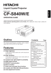
Liquid Crystal Projector
Model name
CP-S833W/E
OPERATING GUIDE
Thank you very much for purchasing this hitachi Liquid Crystal Projector.
Please read this operating guide to use correctly. After reading this manual, keep it carefully for
future reference.
Outline
This Liquid Crystal Projector can display various
computer signals and NTSC/PAL/SECAM video
signals.
Features
(1) High brightness
A highly efficient optical system with a UHP lamp ensures
high brightness.
(2) High resolution
Three separate high-definition liquid crystal panels are
used for the R, G and B signals.
(3) Compact size, light weight for portability
(4)
(5)
(6)
(7)
(8)
RGB output terminal
RS232C Communication
Mouse emulation
Complies with VESA DDC1/2B specifications
Magnifyine function
Contents
Page
Before use ............................3
Names and functions of each
part ................................7
Installation ..........................11
Basic operations ..................12
Adjustments and functions ..15
Connection to the video signal
terminals......................19
Connection to the RGB signal
terminal........................19
Connection to the control
signal terminal ............22
Example of system setup ....27
Cleaning the air filter ..........28
Lamp ..................................29
Message table ....................30
When you think something
wrong ..........................31
Specifications ......................32
FOR THE CUSTOMERS IN U.K
THIS PRODUCT IS SUPPLIED WITH A TWO PIN MAINS PLUG FOR USE IN MAINLAND EUROPE.
FOR THE U.K PLEASE REFER TO THE NOTES ON THIS PAGE.
IMPORTANT FOR UNITED KINGDOM
WORDING FOR CLASS I EQUIPMENT INSTRUCTION BOOKS AND LABELS
The mains lead on this equipment is supplied with a moulded plug incorporating a fuse, the value of which
is indicated on the pin face of the plug. Should the fuse need to be replaced, an ASTA or BSI approved BS
1362 fuse must be used of the same rating. If the fuse cover is detachable never use the plug with the cover
omitted. If a replacement fuse cover is required, ensure it is of the same colour as that visible on the pin
face of the plug. Fuse covers are available from your dealer.
DO NOT cut off the mains plug from this equipment. If the plug fitted is not suitable for the power points
in your home or the cable is too short to reach a power point, then obtain an appropriate safety approved
extension lead or consult your dealer.
Should it be necessary to change the mains plugs, this must be carried out by a competent person,
preferable a qualified electrician.
If there is no alternative to cutting off the mains plug, ensure that you dispose of it immediately, having
first removed the fuse, to avoid a possible shock hazard by inadvertent connection to the mains supply.
WARNING: THIS EQUIPMENT MUST BE EARTHED
IMPORTANT:
The wires in the mains lead are coloured in accordance with the following code:
Green and Yellow=Earth, Blue=Neutral, Brown=Live.
Green & Yellow to Earth
Brown to Live
Fuse
Blue to Neutral
Cord Clamp
As these colours may not correspond with the coloured makings identifying the terminals in your plug,
proceed as follows:
The wire which is coloured Green and Yellow must be connected to the terminal in the plug which is
marked with the letter E or by the earth symbol
or coloured Green or Green and Yellow.
The wire coloured Blue must be connected to the terminal marked with the letter N or coloured BLUE or
BLACK. The wire coloured BROWN must be connected to the terminal marked with the letter L or
coloured BROWN or RED.
2
WARNING:This equipment has been tested and found to comply with the limits for a Class A digital
device, pursuant to Part 15 of the FCC Rules. These limits are designed to provide reasonable protection
against harmful interference when the equipment is operated in a commercial environment. This
equipment generates, uses, and can radiate radio frequency energy and, if not installed and used in
accordance with the instruction manual, may cause harmful interference to radio communications,
Operation of this equipment in a residential area is likely to cause harmful interference in which case
the user will be required to correct the interference at his own expense.
Instructions to Users:
This equipment complies with the requirements of FCC (Federal Communication Commission)
Class A equipments provided that following conditions are met.
(1) Video signal cables:
Double shielded coaxial cables (so called FCC shield cable) must be used and the outer shield must be
connected to the ground. Or, if normal coaxial cables are used, the cables must be enclosed in metal
pipes or similar way to reduce the interference noise radiation.
(2) Power cord:
Shielded power cord must be used. The outer shield must be connected to the ground.
(3) Video inputs:
The input signal amplitude must no exceed the specified level.
Before use
[Before Use]
Illustrated marks
Various illustrated marks are used in this product and instruction manual so
the product is used correctly and safely, and also to protect you and others from
danger and your property from being damaged.
Warning
Caution
Examples of
illustrated marks
This shows that a person could be killed or injured if the
wrong operation is done by ignoring this indication.
This shows that a person could be injured or material may be
damaged if the wrong operation is done by ignoring this
indication.
The
mark informs you that there is a warning (including caution).
The concrete details of the warning (the left diagram shows the
caution for an electric shock hazard) is shown in the diagram.
The
mark informs you of a prohibited action. The concrete
prohibited action (the left diagram shows the prohibition of
disassembly) is drawn in the diagram or near it.
The
mark informs you of actions you must do. The concrete
instruction details (the left diagram shows "Disconnect the power
plug from the power outlet") is drawn in the diagram.
3
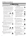
[Safety precaution]
Warning
If any abnormality occurs.
· When there is an abnormal smell or smoke, if
you use this unit as it is, this could cause a fire
or electric shock, etc. When an abnormality is
found, immediately turn off the power switch
and pull out the power plug from the power
outlet. Check that there is no smoke, etc., then
contact your dealer to repair the unit. Do not
repair it yourself as it is very dangerous.
· Do not use this unit as it is after
trouble has occurred,
such as "No picture", "No
sound", "Abnormal
Pull out the
sound", etc. This may cause a fire,
power plug
electric shock, etc. In this case
from the
power
immediately turn off the power
outlet.
switch and disconnect the power
plug, then contact your dealer to repair the
unit.
· If water, etc. enters inside the unit, turn off the
power switch of the unit first and disconnect
the power plug and then contact your dealer.
If you use it as it is, it may cause a fire, electric
shock, etc.
Do not install this unit in an unstable place.
Avoid placing it in an unstable place
such as weak base, inclined floor, etc.
This may cause it to drop or fall over,
resulting in injury.
Do not look directly at the lens when
the lamp is lit.
Do not look directly at the lens when
the lamp is lit. Since a strong light
is used, it could damage you vision, etc.
Especially pay attention if children are present.
Do not insert any foreign object.
· Do not insert a metal or flammable
object inside through the ventilation
holes, etc. This may cause a fire,
electric shock, etc.
· If foreign matter enters inside, turn
the power switch off and disconnect
the power plug from the power
outlet and contact your dealer. If
you use as it is, it may cause a fire,
electric shock, etc. Be careful
especially if children could touch the
unit.
Pull out the
power plug
from the
power
outlet.
Do not apply any shock.
If you drop this unit or if the cabinet
is broken, turn off the power switch,
disconnect the power plug and
contact your dealer. If you use it as
it is, it may cause a fire, electric
shock, etc.
Pull out the
power plug
from the
power
outlet.
Do not remodel this unit.
Do not remodel this unit. It may
cause a fire, electric shock, etc.
Do not open the cabinet.
4
Prohibition
of
disassembly
Do not open the cabinet.
There are high voltage
parts inside the cabinet
and this may cause an Electric shock Prohibition
of
electric shock. Ask your hazard
disassembly
dealer to check inside and adjust and
repair the unit.
Do not put a container, etc. with
Do not use this in a bathroom, etc.
Do not use power supplies other
Do not use this unit in a bathroom,
etc. This may cause a fire, electric
shock, etc.
than that specified.
Do not use
near water
liquid on this unit.
Do not put a vase, flowerpot,
cosmetic container, medicine or
water and small metal objects on this unit. If
liquid spills and enter inside the unit, it may
cause a fire, electric shock, etc.
Do not use this unit with a power
voltage other than specified power
supply voltage. It may cause a fire, electric
shock, etc.
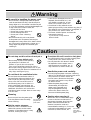
Warning
Be careful in handling the power cord.
· Do not scratch, damage or process the power
cord. Do not bend it forcibly. Also do not put a
heavy object on it, do not heat it and do not pull
it. If you do, the power cord may be damaged and
it may cause a fire, electric shock, etc.
· Do not pull the cord.
· Do not put a heavy object on it.
· Do not damage the cord.
· Do not put it near a heating
device.
· Be careful that this unit is not placed
on the power cord. The power cord may be
damaged and it may cause a fire, electric shock,
etc. If the cord is covered with a carpet, etc. a
heavy object may be put on it without your
realizing it.
· If the cord is damaged (core wire is
exposed, disconnected, etc.), ask
your dealer to replace it. It may
cause a fire, electric shock, etc.
· Check that no dirt adheres to the
power plug and fully insert without any play. If
dirt adheres or the connection is incomplete, it
may cause a fire, electric shock, etc.
· The outer shield of power cord must be
connected to ground.
If you do not, it may cause a
electric shock.
Caution
Do not step on this unit or do not put a
heavy object on it.
· Do not step on this unit. Especially
pay attention if children are
present. If you do, the unit may fall
over or may be broken causing an injury.
· Do not put a heavy object on this unit. If you
do, the unit may fall due to its imbalance or it
may drop, causing an injury.
Do not block the ventilation holes.
Do not block the ventilation holes. If
the ventilation holes are blocked, the
heat inside may build up and it may
cause a fire. Do not use this unit in
the following ways: On its side. In a
poorly ventilated, narrow place. On
a carpet or bedspread. Covered with a
tablecloth. Place this unit so that the
ventilation holes are kept 10cm or more away
from the wall.
Cleaning
Be sure to pull out the power plug
from the power outlet for safety
when cleaning.
Set the caster stoppers.
When this unit is installed on the
table with casters, set the caster
stoppers. If the table moves, it may
fall over, causing an injury.
Do not place this unit in a moist or dusty place.
· Do not place this unit in a moist or dusty place.
It may cause a fire, electric shock, etc.
· Do not place this unit where it would
be exposed to soot or steam, near a
cooking stove or humidifier, etc. It
may cause a fire, electric shock, etc.
Handle the power cord carefully.
· Do not bring the power cord near a heating
device. The shield of the cord may melt and it
may cause a fire, electric shock, etc.
· Do not insert / disconnect the power
plug with wet hands. It may cause
an electric shock.
· When the power plug is to be
disconnected, do not pull the
power cord. The power cord
may be damaged and it may
cause a fire, electric shock, etc.
Be sure to hold the power plug.
Caution when carrying it.
Pull out the power
plug from the
power outlet.
When this unit is to be moved, apply
a cover to the lens and be sure to
disconnect the power plug from the
power outlet and check that all
external connection cords are
removed before moving it. If not, the
cord may be damaged and it may
Pull out the
cause a fire, electric shock, etc.
power plug
from the power
outlet.
5
Caution
Use of batteries.
Caution when replacing the lamp.
· Do not use batteries not specified
for this unit. Do not use new
batteries mixed together with old
ones. This may cause a fire, injury
due to burst of battery, liquid
leakage.
· When inserting batteries in this unit, pay
attention to the direction of the
and polarity indications and
insert the batteries correctly. If the
polarities are confused, it may
cause injury or damage near the
unit due to burst batteries, liquid leakage, etc.
· When replacing the lamp, turn off the power of
the projector and disconnect the power plug
from the power outlet. Then wait for
45 minutes to allow the lamp cool:
Failure to do so could result in a
burn.
· For disposal of used lamp, treat
Pull out the
according to the instruction of
power plug
from the
community authorities.
power
· Since the lamp is made of glass, do
outlet.
not apply shock to it and do not
scratch it.
· Also, do not use old lamp. This could also
cause explosion of the lamp.
· If it is probable that the lamp has exploded
(explosive sound is heard), disconnect the
power plug from the power outlet and ask your
dealer to replace lamp. The lamp is covered by
front glass and air-tight structure, but, in rare
cases, the reflector and the inside of the
projector may be damaged by scattered broken
pieces of glass, and broken pieces could cause
injury when being handled.
· When the lamp has been replaced, reset the
accumulated operation time of the lamp.
Do not reset if the lamp has not been replaced.
When you are not going to use
for a long time.
When you are not going use this unit
for a long time because you are going
on a trip, etc., be sure to pull out the
power plug from the power outlet for
safety. And also apply cover to the
lens so that the lens is not damaged.
Pull out the
power plug
from the
power
outlet.
Clean inside the unit at least once two years.
Ask your dealer to clean inside the unit at least
once two years. If the unit is left
with too much dust inside as it is for
a long this without cleaning, it may
cause a fire. Especially it is effective
to clean before the rainy season
starts. Consult your dealer for the cost of the
cleaning the inside the unit.
Front glass
Reflector
Lamp
[General cautions]
Do not place this unit where it gets hot.
Be careful since if you place the unit
outdoors, in a place exposed to direct
sunlight or near a heating device,
the cabinet and parts could be
affected.
Volume.
Use at the proper volume level so that it does
not bother persons in the neighborhood.
Especially, since the sound is likely to carry
well at the night even at a low volume, consider
the neighborhood to a good living environment.
Cleaning the lens.
To clean the lens, use a generallyavailable lens cleaning tissue (used
for cleaning lens of camera, glasses,
etc.). Be careful not to scratch the
lens with a hard object.
6
Cleaning the cabinet.
· Since many plastic materials are used on the
surface of the cabinet, if the surface is cleaned
using benzene, thinner, etc., it may change in
quality or the coating may be peeled off. Avoid
using chemicals.
· When a chemically-teated cloth is used, follow
the cautions that come with the cloth.
· Do not spray a volatile agent such as
insecticide on the unit. Do not leave a rubber
or vinyl object touching the cabinet for a long
time. It may cause the cabinet to change in
quality or the coating to peel off.
· Clean the dirt from the cabinet and operation
panel by dusting lightly with a soft cloth. If
the dirt is conspicuous, wipe off with a cloth
moistened with detergent diluted with water,
then wipe off with a dry soft cloth.
Rest your eyes occasionally when
viewing for a long time.
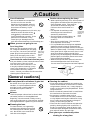
Names and functions of each part
Main unit
MENU button
Picture adjustments.
Refer to page 15~18 for details.
RESET button
INPUT button
Resets unit to factory settings.
(See page 15)
To select the input source.
Each time this button is pressed, the input
source is changed in sequence as shown
below.
RESET
MUTE button
Silences the sound. (Cancels the mute
when the unit is set in mute mode.)
RGB1
MENU
MUTE
LAMP indicator
This lights or blinks when the lamp does
not light. (See page 31)
LAMP
INPUT
ON
RGB2
VIDEO1
VIDEO2
TEMP indicator
This lights or blinks when temperature
inside the projector is too high or when fan
is abnormal.(See page 31)
TEMP
STANDBY / ON button
ON indicator
Power ON/OFF button.
OFF sets the unit in standby mode.
(see page 12~13)
STANDBY/ON
Speaker
This blinks in the standby mode and lights
in the operation mode.(See page 31)
Speaker
ZOOM knob
Adjusts picture size.
(See page 12)
Remote control
sensor
Cooling fan
(exhaust)
Lens
Lens cap
Handle
FOCUS ring
· Use the remote control transmitter within
the range of about 16 feet from the remote
control sensor and within 30°to both the
left and right.
Adjusts focus.
(See page 12)
7
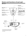
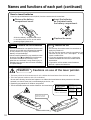
Names and functions of each part (continued)
Remote control sensor
AC IN socket
MAIN POWER switch
Connect the provided power cord.
Main power ON/OFF switch.
: OFF
: ON
RGB input terminal
D-sub 15pin shrink terminal (1/2)
RGB output terminal
D-sub 15pin shrink terminal
RGB output can be displayed
even in the standby mode.
INPUT
RGB IN
S-VIDEO
VIDEO input terminal
(on video-equipped models only)
S-VIDEO input terminal
Mini DIN 4pin connector (1/2)
VIDEO input terminal
RCA Jack (1/2)
AUDIO L/R input terminal
RCA Jack (1/2)
1
RGB OUT
1
2
VIDEO
1
CONTROL
2
2
AUDIO
L
1
2
IN
AUDIO
1
OUT
2
R
CONTROL terminal
D-sub 15pin shrink
terminal
AUDIO output terminal
(RGB/VIDEO)
Stereo mini jack
AUDIO input terminal
Stereo mini jack (1/2)
8
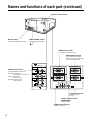
Names and functions of each part (continued)
Remote control transmitter
MUTE button
STANDBY / ON button
Power ON/OFF button.
OFF sets the unit in standby mode.
(See page 12, 13)
FREEZE Button
Silences the sound. (Cancels the mute when
the unit is set in mute mode.)
STANDBY/ON
Pressing this button partially magnifies a
displayed picture. (See page 14)
MAGNIFY VOLUME
OFF
POSITION ON
LASER
DISK PAD
RESET
MENU ON
RIGHT
MOUSE ON
1
When the back light of MENU ON button
on, selects or adjusts the menu item.
(See page 15)
2 When removes the on-screen menus,
works as mouse.
3 When the back light of the POSITION ON
button on, moves picture. *2
LASER button
Laser pointer ON button. Use as a stick (for
indication). (See page 10)
MOUSE LEFT button
Mouse left button is the left click of the
mouse. (bottom button) (See page 22)
POSITION button
Moves the picture by DISK PAD after
pressed the POSITION ON button.
(Only RGB signal input)
While the back light on, you can operate
POSITION. *1
VOLUME button
Adjusts volume. The sound is loud or low
while pressing the "+" or "-" button.
FREEZE
Pressing this button displays a still picture
(by freezing). (See page 14)
MAGNIFY button
MUTE
BLANK
TIMER
RGB
VIDEO
INPUT
RESET / RIGHT button
When displays the on-screen menus, resets
the menu item to factory settings.
When operates the mouse emulation, works
as right click of mouse in computer mode.
(See page 22)
After moving the picture (POSITION ON),
resets the position to factory settings.
MOUSE ON button
Mouse emulation mode starts.
(See page 22)
When menu are open or blank screen is
displayed or icon of position is displayed,
there are stopped and back light off.
MENU ON button
Displays the on-screen menus.
And back light on. (See page 15 ~ 18)
While the back light on, you can operate
MENU.
TIMER ON / OFF button
Displays the setting time by count down.
See page 18 "TIMER" of menu when you set
the minutes of timer.
BLANK ON button
1
The blank screen which is displayed by
pressing BLANK.
2 And the blank screen will be revealed
down by pressing BLANK again.
(See page 18)
INPUT SELECT button
Selects the input source. (See page 12)
*1 POSITION ON icon
*2
When presses POSITION ON button, back light on and icon is
displayed.
While displaying the icon, you can operate POSITION.
Icon is displaying in video mode, but can not operate POSITION.
When the back light of MENU ON or POSITION ON button on
without displaying the icon of POSITION ON or MENU, can
operate DISK PAD too.
Displays the icon or MENU at the same time as starting the
operation.
When presses the MOUSE ON button, MENU mode or
POSITION ON mode is stopped.
9
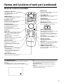
Names and functions of each part (continued)
How to insert batteries
Insert the provided batteries (LR6 (alkal) into the remote control transmitter.
1
Remove the battery
compartment cover.
Slide the battery compartment cover
in the direction of the arrow while
pressing slightly down on it.
Caution
Cautions on use of batteries
· Do not use batteries not specified for this unit.
Also do not use old and new batteries together.
It may cause a fire, injury due to burst of
battery or liquid leakage.
· When inserting batteries, pay attention to the
direction of the
and
polarity indications
and insert the batteries correctly. If the
polarities are confused, it may cause injury or
damage near the unit due to a burst of battery
or liquid leakage.
Caution
2
Insert the batteries
as illustrated inside
the battery compartment.
3
Replace the cover.
Caution
Cautions on use
· Do not drop the remote control transmitter or
apply any shock to it.
· Do not let the remote control transmitter get
wet and do not put it on a wet object. It may
cause a malfunction.
· If you are not going to use it for a long time,
remove the batteries from the remote control
transmitter.
· If operation of the remote control becomes
difficult, replace the batteries.
Cautions on use of the laser pointer.
· The laser pointer on the remote control unit radiates the laser beam from the laser aperture.
· This laser pointer used as a stick (for indication).
· Do not stare directly into the laser aperture or radiate the laser beam to other persons as the laser
emitted is a class II laser and it could damage you vision , etc.
· Especially pay attention if children are present.
RADIAZIONI LASER
· The three labels below are caution labels for the laser beam.
NON GUARDARE NEL RAGGIO LUCE
CAUTION
LASER RADIATION DO NOT STARE INTO BEAM
WAVE LEGTH : 670nm
MAX. OUTPUT : 1mW
CLASS Ⅱ LASER PRODUCT
AVOIDE EXPOSURE-LASER
RADIATION IS EMITTED
FROM THIS APERTURE
LASER APERTURE
10
APPARECCHIO LASER DI CLASS 2
RAYONNEMENT LASER
MANUFACTURED
NE PAS REGARDER DANS
LE FAISCEAU APPAREIL
Jun-99
A LASER DE CLASSE 2
LASER-STRAHLUNG
PLACE OF
NICHT IN DEN STRAHL
BLICKEN LASAER KLASSE 2 MANUFACTURER:D
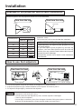
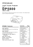
Installation
Example of the projector and screen installation
Determine picture size and projection distance as illustrated below.
View from the top
View from the side
Screen
Lens center
a
Screen (inch)
a (inch)
a:Distance from the projector to the screen.
(tolerance : ±10%)
This screen size is full-screen size.(800 dots X 600 dots)
Minimum
Maximum
40
67
87
Installation of liquid crystal projector
60
98
130
80
130
173
100
165
217
120
197
260
150
248
327
200
331
Please basically use liquid crystal projector at the
horizontal position.
If you use liquid crystal projector by the lens up
position, the lens down position and the side up
position, this may cause the heat inside to build up and
become the cause of damage.
Be especially careful not to install it with ventilation
holes blocked.
How to use foot adjusters
Adjust the projection position using the foot adjusters at the bottom of the projector.
View from the front
Foot adjuster
View from the side
A viewing angle of 0˚~9˚ can be changed.
1. Lift up the projector and press the button of the adjuster to release the lock.
2. Adjust the projection angle, release the button of the adjuster and securely lock it.
3. To adjust the angle slightly, revolve the foot adjusters.
Caution
· Do not unlock the foot adjusters while you do not support the projector, to avoid falling of
the projector and causing an injury.
· Do not revolve the foot adjusters by force, the foot adjusters is damaged.
· Securely lock the adjuster.
· Do not apply unnecessary force from the upper side when lifting the projector. Otherwise,
projector may be damaged or a finger could be caught and cause injury.
11
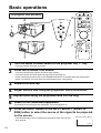
Basic operations
To project the picture
2
4
STANDBY/ON
MUTE
FREEZE
RESET
MAGNIFY VOLUME
OFF
3
MENU
LASER
POSITION ON
MUTE
INPUT
LAMP
5
ON
TEMP
7
STANDBY/ON
RESET
MENU ON
2
7
RIGHT
MOUSE ON
BLANK
TIMER
RGB
VIDEO
INPUT
1
1
Turn the MAIN POWER switch of the projector on.[ I : ON]
2
Press the STANDBY/ON button.
3
4
5
6
Remove the lens cap.
7
· The ON indicator will light up orange.
· The ON indicator blinks (green) and then lights (green).
· The ON indicator will blink green during warm-up and light up.
· Power cannot be turned on even if the STANDBY/ON button is pressed within 60 seconds after
power is turned off, since the lamp has cooled preparing for next lighting.
Adjust picture size using the projection lens ZOOM knob.
Adjust focus using the projection lens FOCUS ring.
Power on all connected equipment.
The method of connecting various equipment, see on the page 19~27.
Press the INPUT button or the INPUT SELECT (VIDEO or
RGB) button to select the source of the signal to be projected
on the screen.
Example on-screen display
· The selected signal input is displayed at the bottom right of the screen
for 3 seconds.
RGB1
12
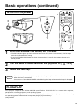
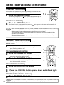
Basic operations (continued)
To turn off the power
STANDBY/ON
1
MUTE
FREEZE
RESET
MAGNIFY VOLUME
3
OFF
POSITION ON
MENU
MUTE
LASER
INPUT
LAMP
ON
TEMP
STANDBY/ON
RESET
MENU ON
1
RIGHT
MOUSE ON
BLANK
TIMER
RGB
VIDEO
INPUT
2
1
Press the STANDBY/ON button, for 1 second.
2
Turn the MAIN POWER switch of the projector off.[
3
Install the lens cap.
· The ON indicator lights up orange and the lamp turns off. (About 1 minute later), the fan stops
and the indicator blinks orange.
· Press the STANDBY/ON button for short time (less than 1 second), the projector do not set in
standby mode.
Caution
: OFF]
· To reduce temperature inside the projector (cooling down), fan will rotate for about 1 minute
after the lamp is turned off.
· Do not turn off the MAIN POWER switch during the lamp on because the lamp is damaged.
PLUG&PLAY
This projector complies with VESA DDC1/2B specifications. PLUG&PLAY is a system with computer,
peripherals (including projectors), and operating system.
It works when the projector is connected to DDC (Display Data Channel) ready computer that is running
an operating system software that incorporates plug & play functionality.
(Only RGB 1)
13
Basic operations (continued)
FREEZE FUNCTION
This function can display a still picture (by freezing). This function can
be used in combination with a MAGNIFY function.
1
Press the FREEZE button.
STANDBY/ON
MUTE
FREEZE
1, 2
MAGNIFY VOLUME
OFF
The display image stops. A mark appears at the lower right of
the screen for about 3 seconds during the FREEZE function.
POSITION ON
LASER
[TO RELEASE FREEZE]
2
Press the FREEZE button.
The freeze function is cancelled. Furthermore, a
seconds or so when FREEZE is released.
mark appears at the bottom of the screen for 3
Caution · Note: When the FREEZE Button is pressed, FREEZE and RELEASE can function alternately.
· What is more, FREEZE is released when an input selector button is pressed or when the
display mode of a personal computer is switched over during display.
· The POSITION ON icon is not displayed during freeze. Also, scrolling using DISK PAD
operation is not possible.
· When a still picture signal is given as input and the freeze function is ON, do not forget to
cancel the freeze function.
MAGNIFYING FUNCTION
It is possible to display a partially magnified picture. This function can be used in combination with a
FREEZE function.
1
Press the MAGNIFY + button.
· By doing so, the center of the picture can be magnified as one
part, becoming double in size.
[TO CHANGE MAGNIFICATION]
2
3
Press the MAGNIFY + button.
· When the button is pressed, more magnification of display
takes place. (Maximum about 4 times)
Press the MAGNIFY - button.
· When the button is pressed, the magnified display reduces its
size. (Minimum about 1.1 times)
STANDBY/ON
1, 2
6
4
5
MUTE
FREEZE
MAGNIFY VOLUME
OFF
POSITION ON
LASER
3
RESET
MENU ON
RIGHT
MOUSE ON
BLANK
[TO SHIFT DISPLAY AREA]
TIMER
RGB
VIDEO
INPUT
4
5
Press the POSITION ON button.
Press the DISK PAD button up and down and left and right.
· The magnified display area shifts in the direction the button is pressed.
[TO RETURN TO NORMAL DISPLAY]
6
Press MAGNIFY OFF button.
Caution
14
Note: The MAGNIFY function is released when an input selector button is pressed or when the
display mode of a personal computer is switched over during display.
Adjustments and functions
STANDBY/ON
MUTE
FREEZE
RESET
MAGNIFY VOLUME
OFF
MENU
POSITION ON
MUTE
LAMP
LASER
INPUT
ON
TEMP
2, 3
STANDBY/ON
RIGHT
RESET
1, 2, 3
1
MENU ON
MOUSE ON
BLANK
TIMER
RGB
VIDEO
INPUT
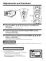
1
Press the MENU (
OFF button.
) buttons or the MENU ON /
· On-screen menus are displayed on the screen.
2
Select the menu to be adjusted using the MENU (
buttons or DISK PAD.
)
· Menu displayed in green is selected.
3
Select the item to be adjusted using the MENU (
buttons or DISK PAD.
)
· Item displayed in green can be adjusted.
When no operation is done for about 5 ~ 10 seconds, menu screen will go off.
Memory function
Individual memory functions are provided for the VIDEO1, VIDEO2, RGB1 and RGB2 input terminals.
Adjustments are saved after power off.
To return to the initial setting
· Resetting menu items (SETUP, INPUT, IMAGE, OPT.)
(1) Select the menu item to return to the initial setting.
(2) Press the RESET button.
(3) Select the DEFAULT (To select the CANCEL is not changed).
(Display shown on the right will appear.)
· Resetting adjustment items (VOLUME, BRIGHT etc.)
(1) Select the adjustment item to return to the initial setting.
(2) Press the RESET button.
SETU P IN PU T IMAG E OPT.
VOLUME
BRIGHT RESET 'SETUP'
CONTRAST
DEFAULT
SHARPNESS CANCEL
COLOR
TINT
COLOR BAL
R
B
15
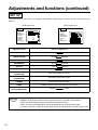
Adjustments and functions (continued)
SET UP
The menu SET UP serves for the change of parameters influencing the picture and for the move picture
position.
RGB signal input
SETUP
INPUT
VOLUME
BRIGHT
CONTRAST
V POSIT
H POSIT
H PHASE
H SIZE
COLOR BAL
Adjustment Item
VOLUME
OPT.
SETU P IN PU T IMAGE O PT.
VOLUME
BRIGHT
CONTRAST
SHARPNESS
COLOR
TINT
COLOR BAL
121
57
7
800
R
B
R
Decrease
Increase
Dark
CONTRAST
Lower
SHARPNESS
Soft
Sharp
COLOR
Less
More
TINT
Red
Green
Bright
Higher
V.POSIT
(V.POSITION)
Moves the picture up or down.
H.POSIT
(H.POSITION)
Moves the picture left or right.
H.PHASE
Decreases the picture flicker.
H.SIZE
Windens of Narrow the horizontal size of the picture.
Caution
B
Details of adjustment
BRIGHT
(BRIGHTNESS)
COLOR BAL
(COLOR BALANCE)
16
IMAGE
VIDEO signal input
for Red
for Blue
· When start up screen is displayed ("NO INPUT IS DETECTED"or "SYNC IS OUT OF
RANGE" is displayed), SETUP menu items other than VOLUME cannot be set.
· TINT cannot be adjusted with PAL/SECAM video signal input.
· TINT, COLOR and SHARPNESS cannot be adjusted with an RGB signal input.
· V.POSIT, H.POSIT, H.PHASE and H.SIZE cannot be adjusted with a VIDEO signal input.
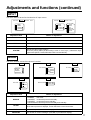
Adjustments and functions (continued)
INPUT
The menu INPUT serves for the selection of input source.
SETUP
INPUT
IMAGE
OPT.
SETU P IN PU T IMAGE O PT.
SYSTEM
AUTO
NTSC
PAL
SECAM
NTSC4.43
M-PAL
RGB1
RGB2
V I DEO1
V I DEO2
RGB1
RGB2
VIDEO1
VIDEO2
Adjustment Item
Details of adjustment
RGB 1
Selects the RGB 1 terminal.
RGB 2
Selects the RGB 2 terminal.
VIDEO 1
Selects the VIDEO 1 terminal.
VIDEO 2
Selects the VIDEO 2 terminal.
SYSTEM
Selects the video signal systems.
When the picture (Video) is abnormal (no color or out of sync.), selects the input
signal mode (NTSC, PALM, SECAM, NTSC4.43 and M-PAL).
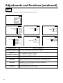
IMAGE
The menu IMAGE serves of the picture inversion.
SETUP
INPUT
IMAGE
OPT.
SETUP
MIRROR
MIRROR
BLANK
REVEAL
MESSAGE
SETUP
INPUT
IMAGE
REVEAL
INPUT
OPT.
SETUP
INPUT
MESSAGE
FAST
IMAGE
OPT.
SETUP
NORMAL
H : INVERT
V : INVERT
H&V :
INVERT
IMAGE
INPUT
IMAGE
BLANK
OPT.
WHITE
BLUE
BLACK
OPT.
TURN ON
TURN OFF
MEDIUM
SLOW
Adjustment Item
Details of adjustment
MIRROR
Inverts the picture horizontally or vertically.
NORMAL
Not invert.
H:INVERT Inverts the picture horizontally.
H:INVERT Inverts the picture vertically.
H&V:INVERT Inverts the picture horizontally and vertically.
BLANK
Selects the blank color of signal or pressing BLANK ON button.
When start up screen is displayd, screen will blank out 5 minutes later.
REVEAL
Selects the speed or revelation. See page 9 "BLANK ON button.
MESSAGE
Turn off the on-screen message. (VOLUME, Input selection display)
17
Adjustments and functions (continued)
OPT.
The menu OPT. allows you to control communication function etc.
SETUP
INPUT
IMAGE
OPT.
COM. SPEED
COM. BITS
TIMER
LANGUAGE
AUTO OFF
START UP
SETUP
INPUT
IMAGE
COM. SPEED
(bps)
SETUP
INPUT
OPT.
1200
2400
4800
9600
19200
IMAGE
LANGUAGE
Adjustment Item
COM. SPEED
(COMMUNICATION SPEED)
(COMMUNICATION BITS)
TIMER
LANGUAGE
18
OPT.
ENGLISH
FRANÇAIS
DEUTSCH
ESPAÑOL
ITALIANO
NORSK
NEDERLANDS
COM. BITS
SETUP
INPUT
IMAGE
INPUT
SETUP
7N1
8N1
COM. BITS
SETUP
OPT.
IMAGE
OPT.
INPUT
TIMER
SETUP
INPUT
START UP
AUTO OFF
IMAGE
0 min.
STOP
OPT.
15 min.
IMAGE
OPT.
TURN ON
TURN OFF
Details of adjustment
Selects the data speed of transmission. (five kinds)
Selects the data format or transmission
7N1...7 data bits, No parity, 1 stop bit.
8N1...8 data bits, No parity, 1 stop bit.
Sets the minutes of timer. (0~99)
Selects the language on-screen menu.
(English, Francais, Deutsch, Espanol, Italiano, Norsk, Nederlands)
AUTO OFF
Sets time (minutes) from the start of displaying start up screen (No input is
detected or sync is out of range) to turning the power OFF.
"0" is stop and another "1~99"
START UP
Sets/releases start up screen displayed when power is turned on, or when no
input is detected or sync is out of range.
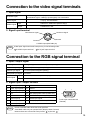
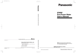
Connection to the video signal terminals
1. Input signal
Luminance signal
1.0Vp-p, 75W termination
Chrominance signal 0.286Vp-p (burst signal), 75W termination
S-VIDEO signal
1.0Vp-p, 75W termination
VIDEO signal
Input
200mVrms, 20kW below (MAX 3.0Vp-p)
Output
0~200mVrms, 1kW
AUDIO signal
2. Signal input terminal
Chrominance signal
Ground
Luminance signal
Ground
S VIDEO input (Mini DIN4 pin)
Caution
Video input signal terminals have priority in the following order.
1
S-VIDEO input terminal
2
RCA jack input terminal
Connection to the RGB signal terminal
1. Input / output signal
Video signal
Analog 0.7Vp-p 75W termination (Positive polarity)
Horizontal sync signal
TTL level (Positive/negative polarity)
Vertical sync signal
TTL level (Positive/negative polarity)
Composite sync signal
TTL level
Input
200mVrms, 20kW below (MAX 3.0Vp-p)
Output
0~200mVrms, 1kW
Audio signal
2. Signal input / output terminal
1
Video signal (Red)
9
N.C
2
Video signal (Green)
10
Ground
3
Video signal (Blue)
11
N.C
4
N.C
12
DDC (Display Data channel) RGB1 only
5
N.C
13
Horizontal/Composite sync signal
6
Ground (for R)
14
Vertical sync signal
7
Ground (for G)
15
DDC (Display Data channel) RGB1 only
8
Ground (for B)
Caution
5
1
10
6
15
11
D-sub 15pin shrink terminal
(Female)
Do not use RGB cable other than that specified.
Some RGB cable may not operate DDC (Display Data Channel)
because there are not connect from pin NO. 15 to pin NO. 12 .
19
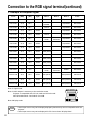
Connection to the RGB signal terminal(continued)
3. Example of computer signal
Resolution
HXV
fH
(kHz)
fV
(Hz)
640 X 350
31.5
70.1
640 X 400
24.8
640 X 400
Standard
Type
Note 3
Display Dots
HXV
VGA-1
Expanded
800 X 490
56.4
NEC
PC9800
Expanded
800 X 560
31.5
70.1
VGA-2
Expanded
800 X 560
640 X 480
43.3
85.0
VESA
Expanded
800 X 600
640 X 480
31.5
59.9
VESA
Expanded
800 X 600
640 X 480
35.0
66.7
Expanded
800 X 600
640 X 480
37.9
72.8
VESA
Expanded
800 X 600
640 X 480
37.5
75.0
VESA
Expanded
800 X 600
800 X 600
35.2
56.3
VESA
SVGA (56Hz)
800 X 600
800 X 600
37.9
60.3
VESA
SVGA (60Hz)
800 X 600
800 X 600
48.1
72.2
VESA
SVGA (72Hz)
800 X 600
800 X 600
46.9
75.0
VESA
SVGA (75Hz)
800 X 600
800 X 600
53.7
85.1
VESA
SVGA (85Hz)
800 X 600
832 X 624
49.7
74.5
1024 X 768
48.4
60.0
VESA
1024 X 768
56.5
70.1
1024 X 768
60.0
75.0
Note 1
Note 2
VGA-3
Mac13"
mode
Mac16"
mode
SW 1 ON
SW 2 ON
SW 2 ON
SW 4 ON
Partial
800 X 600
XGA (60Hz)
Compressed
768 X 576
VESA
XGA (70Hz)
Compressed
768 X 576
VESA
XGA (75Hz)
Compressed
768 X 576
Note 1: Signal mode
Note 2: MAC adapter is necessary to the resolution mode.
Projector is compatible with 13 inch mode and 16 inch mode.
MAC13"mode=switch 1 and switch 2 are ON.
MAC16"mode=switch 2 and switch 4 are ON.
ON
1 2 3 4 5 6
OFF
Note 3:Display mode
(Example 16inch mode)
Caution
20
· Some input source may not be displayed properly because they are not compatible with the
projector.
· Some input source may not be displayed in full size as shown "Display Dots".
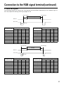
Connection to the RGB signal terminal(continued)
4. Initial set signals
The following signals are initially set. The settings may be different depending on the computer type. In
this case, adjust the settings referring to pages 15, 16.
Back porch(b)
Front porch(d)
Active(c)
DATA
HSYNC
Sync.(a)
Computer/signal
VGA-1
PC-9800
VGA-2
VESA (85Hz)
VGA-3
Mac 13inch mode
VESA (72Hz)
VESA (75Hz)
SVGA (56Hz)
Horizontal Timing (µs)
a
b
c
d
3.8
1.9
25.4
0.6
3.0
3.8
30.4
3.0
3.8
1.9
25.4
0.6
1.6
2.2
17.8
1.6
3.8
1.9
25.4
0.6
2.1
3.2
21.2
2.1
1.3
4.1
20.3
0.8
2.0
3.8
20.3
0.5
2.0
3.6
22.2
0.7
Computer/signal
SVGA (60Hz)
SVGA (72Hz)
SVGA (75Hz)
SVGA (85Hz)
Mac 16inch mode
XGA VESA (60Hz)
XGA VESA (70Hz)
XGA VESA (75Hz)
Horizontal Timing (µs)
a
b
c
d
3.2
2.2
20.0
1.0
2.4
1.3
16.0
1.1
1.6
3.2
16.2
0.3
1.1
2.7
14.2
0.6
1.1
3.9
14.5
0.6
2.1
2.5
15.8
0.4
1.8
1.9
13.7
0.3
1.2
2.2
13.0
0.2
Front porch(d)
Back porch(b)
Active(c)
DATA
VSYNC
Sync.(a)
Computer/signal
VGA-1
PC-9800
VGA-2
VESA (85Hz)
VGA-3
Mac 13inch mode
VESA (72Hz)
VESA (75Hz)
SVGA (56Hz)
Vertical Timing (lines)
a
b
c
d
2
59
350
38
8
25
400
7
2
34
400
13
3
25
480
1
2
33
480
10
3
39
480
3
3
28
480
9
3
16
480
1
2
22
600
1
Computer/signal
SVGA (60Hz)
SVGA (72Hz)
SVGA (75Hz)
SVGA (85Hz)
Mac 16inch mode
XGA VESA (60Hz)
XGA VESA (70Hz)
XGA VESA (75Hz)
Vertical Timing (lines)
a
b
c
d
4
23
600
1
6
23
600
37
3
21
600
1
3
27
600
1
3
39
624
1
6
29
768
3
6
29
768
3
3
28
768
1
21
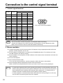
Connection to the control signal terminal
1. Control signal terminal
Pin No.
RS-232C
Mouse
PS/2
ADB
Serial
1
2
CLK
3
DATA
DATA
1
5
4
10
6
5
6
SELO
SELO
SELO
7
RTS
RTS
RTS
+5V
+5V
GND
GND
RTS
11
15
D-sub 15pin shrink terminal (Male)
8
9
10
GND
GND
11
12
13
RTD
14
TDP
TD
15
Caution
Turn off the power of both the projector and computer before connecting.
Connect the computer to the control terminal of the projector using an appropriate cable.
Refer to the instruction manual of each device before connecting.
2. Mouse emulation
(1) Connect the projector and the mouse terminal of computer using an appropriate cable, while the
projector and the computer are turn off.
(2) Turn the power of the projector on and press the STANDBY/ON switch. The indicator will light.
(The ON indicator will light up orange.).
(3) Press the INPUT of the projector or RGB 1/2 button of the remote control transmitter and select the
input connection.
(4) Turn on the computer.
(5) Start mouse emulation mode.
If can not start mouse emulation, reset the computer. (With soft reset or reset switch)
(6) See on the page 9 about to operate the remote control transmitter.
Caution : Mouse cannot be operated while start up screen or menu screen is being displayed.
Caution
22
· In some note computers which have internal pointing device, mouse emulation don't work
without setting the internal pointing device disabled. In this case, set the internal pointing
device disabled in BIOS setting. After setting in BIOS, operate (1) ~ (5) Please check its
hardware manuals to disable internal pointing device in BIOS setting.
· In some computers, mouse emulation don't work without the utility program. In this case,
see and check the operating manuals of the computer.
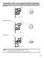
Connection to the control signal terminal (continued)
PS/2 mouse
Projector
1
CLK 2
DATA 3
4
5
SEL0 6
RTS 7
8
+5V 9
GND 10
11
12
13
14
15
Computer
1
2
3
4
5
6
DATA
Mini Din 6pin
GND
+5V
CLK
6
5
3
4
2
1
PS/2 cable
ADB (Mac) mouse
Projector
Computer
1
2
3
4
5
6
7
8
9
10
11
12
13
14
15
ADB cable
Projector
Computer
DATA
RTS
+5V
GND
1
2
3
4
ADB
(POWER ON)
+5V
GND
Mini Din 4pin
3
4
1
2
Serial mouse
SEL0
RTS
GND
TD
Caution
1
2
3
4
5
6
7
8
9
10
11
12
13
14
15
1
2
3
4
5
6
7
8
9
CD
RD
TD
DTR
GND
DSR
RTS
CTS
RI
D-sub 9pin
1
2
6
3
7
5
4
8
9
Serial cable
Serial mouse cannot be operated with provided RS-232C cable.
Purchase exclusive serial mouse cable separately.
Type name : SC-MS201X (Serial mouse)
Parts No. : EW02882
23
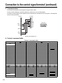
Connection to the control signal terminal (continued)
3. Communication
(1) Connect the projector and computer using RS 232C cable.
(2) Turn off the computer and after computer is setting up, turn on the projector.
(3) Select the data speed (COM.SPEED) and the data format (COM.BITS) of the projector. (See page 18)
(4) Start communication.
Projector
SEL0
RTS
GND
RDP
TDP
Computer
1
2
3
4
5
6
7
8
9
10
11
12
13
14
15
1
2
3
4
5
6
7
8
9
CD
RD
TD
DTR
GND
DSR
RTS
CTS
RI
D-sub 9pin
1
2
6
3
7
5
4
8
9
RS232C cable (Reference)
4. Control command table
Control command table
Item
MOUSE
COMMUNICATE
POWER
MIRROR
INPUT
(VIDEO) SYSTEM
VOLUME
MUTE
BRIGHT
CONTRAST
COLOR
TINT
SHARPNESS
H. PHASE
H. POSIT
H. SIZE
V. POSIT
BLANK
REVEAL
MAGNIFY
FREEZE
24
Projector
Computer
Reply code
1st
2nd
data
11h
05h
+1
11h
06h
+1
11h
11h
+1
11h
14h
+1
11h
21h
+1
12h
22h
+2
11h
23h
+1
11h
24h
+1
13h
31h
+3
13h
32h
+3
13h
33h
+3
13h
34h
+3
13h
35h
+3
13h
37h
+3
14h
38h
+4
14h
36h
+4
14h
3Ah
+4
11h
41h
+1
11h
42h
+1
11h
15h
+1
16h
15h
+6
11h
16h
+1
Ask code
1st
2nd
20h
05h
20h
06h
20h
11h
20h
14h
20h
21h
20h
22h
20h
23h
20h
24h
20h
31h
20h
32h
20h
33h
20h
34h
20h
35h
20h
37h
20h
38h
20h
36h
20h
3Ah
20h
41h
20h
42h
20h
15h
20h
16h
Computer
Projector
Set code
2nd
data
1st
+1
31h
05h
+1
31h
06h
11h
+1
31h
+1
31h
14h
+1
31h
21h
32h
22h
+2
31h
23h
+1
+1
31h
24h
33h
31h
+3
33h
32h
+3
33h
+3
33h
34h
+3
33h
33h
35h
+3
37h
+3
33h
+4
34h
38h
34h
36h
+4
+4
34h
3Ah
+1
31h
41h
31h
42h
+1
36h
31h
15h
16h
+6
+1
Default code
2nd
1st
05h
40h
06h
40h
40h
40h
40h
40h
40h
40h
40h
40h
40h
40h
40h
40h
40h
40h
40h
14h
21h
22h
23h
24h
31h
32h
33h
34h
35h
37h
38h
36h
3Ah
41h
40h
15h
40h
16h
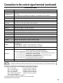
Connection to the control signal terminal (continued)
Control data table
Item
MOUSE
Data code
POWER
00h=stop mouse emulation. 01~7Fh=start mouse emulation
0Xh=8N1
1Xh=7N1
X0h=1200bps, X1h=2400bps, X2h=4800bps, X3h=9600bps, X4h=19200bps
1Eh=Power off (Standby mode), 1Fh=Power on
MIRROR
00h=Normal, 01h=H:Invert, 02h=V:Invert, 03h=H&V:Invert
INPUT
11h=VIDEO1, 12h=VIDEO2, 21h=RGB1, 22h=RGB2
VIDEO
SYSTEM
00h 00h=Auto, 00h 01h=NTSC, 00h 04h=NTSC4.43
00h 02h=PAL, 00h 03h=SECAM, 00h 05h=M-PAL
VOLUME
00h (min) ~ 24h (max)
MUTE
00h=Mute off, 01h=Mute on
BRIGHT
00h 00h 00h (dark) ~ 00h 00h 24h (brite)
CONTRAST
00h 00h 00h (lower) ~ 00h 00h 24h (higher)
COLOR
00h 00h 00h (less) ~ 00h 00h 24h (more)
TINT
00h 00h 00h (red) ~ 00h 00h 24h (green)
SHARPNESS
00h 00h 00h (soft) ~ 00h 00h 24h (sharp)
H. PHASE
00h 00h 00h ~ 00h 00h 1Fh
H. POSIT
00h 00h 00h 00h (left) ~ 00h 00h 37h 04h (right)
H. SIZE
00h 00h 78h 05h (narrow) ~ 00h 00h 30h 0Eh (wide)
V. POSIT
00h 00h 01h 00h (down) ~ 00h 00h 58h 04h (up)
0Xh=Blank off
1Xh=Blank on
bit0 0=Blue off, 1=Blue on, bit1 0=Green off, 1=Green on
bit2 0=Red off, 1=Red on, bit3 0=Not change, 1=change
X1h=Reveal down, X4h=Reveal right, X=0 (slow) ~ 7 (fast)
COMMUNICATE
BLANK
REVEAL
MAGNIFY
(1) Circuit codes when ask code and default set code are issued (Number of data byte=1)
00h=normal display, 01h=magnified display
(2) When magnification is set by setting codes (Number of data bytes=6)
1st, 2nd data bytes: magnification starting positions in horizontal direction (left end)
00h 00h (left) ~ 3Ch 05h (right)
3rd, 4th data bytes: magnification starting positions in vertical direction (top)
00h 00h (top) ~ 0Dh 04h (bottom)
5th, 6th data bytes: Horizontally magnified dot number data
64h 00h (large) ~ 20h 06h (small)
FREEZE
00h=normal display, 01h=still picture display
Caution
If computer sends the undefined command code or data code, Projector can not guarantee operation.
Command is consisted of 2 command bytes and following data bytes.
1-st byte indicates the kinds of commands and the length of command.
'0xH' : Error-reply
Projector sends to computer.
'1xH' : Command reply
Projector sends to computer.
'2xH' : Ask command
Computer sends to Projector.
'3xH' : Set command
Computer sends to Projector.
'4xH' : Default set command
Computer sends to Projector
'5xH' - 'FxH' : Reserved
'x' indicates the length of data bytes.
2-nd byte indicates the command code 'yy' as command table.
Data table shows the data byte.
25
Connection to the control signal terminal (continued)
The procedure of getting the Projector status
(1)Computer sends the command '20H'+'yyH' to Projector.
(2)Projector reply the command '1xH'+'yyH'+data bytes.
The procedure of setting the Projector status
(1)Computer sends the command '3xH'+'yyH'+data bytes.
(2)Projector changes it’s status.
(3)Projector reply the command '1xH'+'yyH'+data bytes which indicate status.
Caution
· (3) data bytes is not always same as (1) data bytes. If projector cannot realize the status of (1)
data bytes, projector set the proper status and reply this new setting data bytes or projector
reply the error reply '0xH'+'yyH'+data bytes same as (1).
· When only power control (POWER COMMAND) is performed, it takes about 2~80 seconds
between sending set code and receiving answering code.
The procedure of default setting the Projector status
(1)Computer sends the command '40H'+'yyH'
(2)Projector changes it's status to default setting.
(3)Projector reply the command '1xH'+'yyH'+data bytes which indicate default.
Caution
If projector replys '4Dh', (before command code, etc.) computer ignores '4Dh'
The example of command error
When projector cannot accept command from PC, error code '00H'+'yyH' is sent back.
(in a case when command code '2xH', '3xH' or '4xH'+'yyH'+data is sent from PC to projector)
The example of data error
When projector cannot accept command from PC, error code with data '00H'+'yyH'+data is sent back as it
is. (in a case when command code '2xH', '3xH' or '4xH'+'yyH'+data is sent from PC to projector)
When data is longer than required data code length, projector ignores excess data code.
When data is shorter than required data code length, projector sends back error code shown above.
The example of framing error
After setting to 1200bps 7N1, projector sends error code '70H'+'70H' up to 10 times at intervals of 1 second
until any answer is received. When projector receives framing error code ('70H'+'70H'),
'12H'+'03H'+'03H'+'10H' is sent with 1200 bps 7N1.
The interval of command bytes and data bytes
After command code '2xH', '3xH' or '4xH' is sent from PC, if command or data is not sent within 500ms,
projector sends back error command '70H'+70H'. If no answer is sent within 1 second from that time,
framing error is assumed.
Caution
26
· The interval of command bytes and data bytes must be over 1mS and under 500mS. If it is
under 1mS, it may be treat as framing error.
· After projector has sent back answer code, when next command is to be sent from PC, allow
for an interval of 40ms or more between answer code and other code.
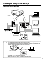
Example of system setup
Connecting various equipment.
AC Inlet
Computer (Note type)
INPUT
S-VIDEO
1
2
RGB IN
RGB OUT
VIDEO
1
1
2
CONTROL
AUDIO
L
1
2
2
R
IN
AUDIO
1
CRT Display
OUT
2
VTR, etc.
(video model only)
VTR with S-VHS out
(video model only)
Computer(Desk type)
Audio amplifying equipment
Caution
· To protect from radio interference, core is attached to each provided or optional cable: Do
not use cables other than provided cables and optional cables.
· Since both ends of audio cable are the same shape, either end can be connected to any side.
However, use the cable with the core set to the projector side.
1
Liquid crystal projector
Core
Computer
· Turn power off to all devices before connecting.
· Refer to the instruction manual of each device before connecting.
27
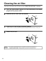
Cleaning the air filter
Clean the air filter about every 100 hours or when "CHECK THE AIR FLOW" is displayed.
1
Turn the main power switich off and disconnect the power
plug from the power outlet.
2
Remove the air filter from the bottom.
3
Clean the air filter using a vacuum cleaner.
4
Install the air filter.
· When air filter is very dirty, wash it using neutral detergent diluted with water, and dry well.
Caution
28
· If air filter is stutted with dust, etc., protection circuit will turn the power off.
· "CHECK THE AIR FLOW" is displayed when you block the ventilation holes.
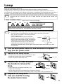
Lamp
Light source lamp has a service life.
The picture will become dark or color will be poor when the lamp is used for a long time.
If usage of lamp is continued in such cases, it could cause a malfunction. Replace lamp with new one.
As reference for replacement time, indicator will operate or message will be displayed when the power is
turned on, as shown on page 30~31. In these cases the lamp should be replaced. Consult your dealer.
Caution
Also LAMP indicator will light when the lamp becomes too hot. Turn off the power and let the
projector cool for 45 minutes. Turn on. If LAMP indicator still lights up red, contact your
dealer.
1. How to replace lamp
(Option lamp : Lamp unit DT00181)
HIGH VOLTAGE
HIGH TEMPERATURE
HIGH PRESSURE
When replacing lamp, turn off and remove AC cord, wait 45 minutes to let lamp cool.
High-pressure lamp when hot, may explode if improperly handled.
Caution
· For disposal of used lamp, treat according to the instruction of community authorities.
· Since the lamp is made of glass, do not apply shock to it and do not scratch it.
· Also, do not use old lamp. This could also cause
explosion of the lamp.
· If it is probable that the lamp has exploded
Reflector
Front glass
(explosive sound is heard), disconnect the power
plug from the power outlet and ask your dealer to
replace lamp. The lamp is covered by front glass
and air-tight structure, but, in rare cases, the
Lamp
reflector and the inside of the projector may be
damaged by scattered broken pieces of glass, and broken pieces could cause injury when
being handled.
1
Turn the main power switch off and disconnect the power
plug from the power outlet.
2
Remove the lamp cover.
3
· If lamp is hot at this time, this could cause burn. Wait
for about 45 minutes until lamp is cooled down.
· Loosen a screw and remove the cover.
Loosen two screws and pull
the handle to remove the
lamp.
Screw
Lamp cover
Screw
· If the screws are not loosened completely, your
Lamp
fingers may be damaged.
· Do not insert your hand into the box after the lamp is removed.
(There are optical parts inside. If touched by hand, it may result in color unevenness, etc.)
4
Replace the lamp with
new one and fix it using
the same two screws.
29
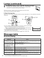
Lamp (continued)
5 Install the lamp cover and fix it using screws.
· To prevent burn, install the lamp cover and secure it using the screws.
· Do not turn on the power with lamp cover removed.
Whenever the lamp is replaced, reset the total operation time of the lamp.
Do not reset if the lamp has not been replaced.
2. Reset the lamp time
Please carry out the following operation within 10 minutes from power on, if you replaced the lamp after
2,000 hours.
VOLUME
MAGNIFY
OFF
RESET
POSITION ON
3
3
RIGHT
RESET
2
MENU
MUTE
MENU ON
1, 2
LASER
MOUSE ON
1
LAMP
INPUT
ON
TEMP
STANDBY/ON
BLANK
TIMER
RGB
VIDEO
INPUT
1) Press the RESET button on projector for 3 seconds or remote control TIMER
button for 3 seconds and display the total lamp used time.
· When accumulated operation time of the lamp reaches 1700 hours, the
following display will appear at the bottom of the screen.
2) Press the RESET button on projector or remote control MENU ON button
during displaying the lamp used time.
3) Select the “0” on the screen using the MENU (
) button or DISK PAD.
LAMP 1700 h
LAMP 1700 □→ 0 ■CANCEL
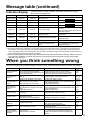
Message table
On-screen display
The following messages are displayed on the screen.
MESSAGE
Action
CHANGE THE LAMP
"AFTER REPLACING LAMP,
RESET THE LAMP TIMER."
Accumulated operation of lamp has exceeded 1,700 hours. It is recommended
to replace lamp. Replace with new lamp. If accumulated operation reaches
2,000 hours, lamp will automatically turn off. *1
Lamp has 1,979 hours on it.
Call a maintenance person. *1
Time is 20 ~ 0. (count down.)
CHANGE THE LAMP
"AFTER REPLACING LAMP,
RESET THE LAMP TIMER."
THE POWER WILL TURN
OFF AFTER 20 Hr.
30
Bilnking of
"CHANGE THE LAMP"
When the lamp has 2,000 hours or more on it, the message will blink, and the
power will turns off after 10 minutes.
NO INPUT IS DETECTED
Signal is hot input. (See page 19, 20)
SYNC IS OUT OF RANGE
The horizontal frequency of the input signal exceeds the range of the projector,
it cannot be displayed. (See page 20, 21)
CHECK THE AIR FLOW
Clean the air filter of remove the blocking ventilation holes. (See page 28)
*1 This message are not displayed after 3 minutes.
But this message are displayed when you turn on the power again.
Message table (continued)
Indicator display
ON indicator
The ON indicator, LAMP indicator and TEMP indicator will light or
blink in the following cases.
LAMP indicator TEMP indicator
Meaning
Remedy
Lights orange
Goes off
Goes off
Standby mode
Blinks green
Goes off
Goes off
During warming up
Lights green
Goes off
Goes off
During operation *1
Blinks orange
Goes off
Goes off
During cooling down
Lights red
Lights red
Goes off
Lamp cannot light
Lights red
Blinks red
Goes off
Lamp is not inserted or the Securely insert the lamp or close the
lamp door open
lampe door.
Lights red
Goes off
Lights red
Lights red
Goes off
Blinks red
Blinks red
Blinks red
Goes off
Cool projector by power off for 45
minutes.
If the indicator is still it, lamp may be
defective. Replace.
Temperature inside too hight
Correctly reinstall so as not to block
ventilation holes.
Cooling fan accidented
Call a maintenance person.
Accumulated lamp operation
time has exceeded 2,000
hours
Replace lamp and reset the
accumulated lamp operation time.
(See page 29, 30)
When the LAMP indicator lights, turn the power off. If the problem cannot be recovered, contact your dealer.
*1 Even when the indicator lights green, if the power supply section becomes too hot , the lamp may be automatically
turned off to cool it down (indicator continues to light green). In this case, turn off the power switch and allow the
unit to cool down before turning the power switch on again. The lamp will light. If the lamp does not light because it
is still automatically turned off, contact your dealer.
*2 When inside temperature becomes high because ventilation holes are blocked, normally, TEMP indicator
will light red. However, to protect the projector, the lamp may be turned off and at this time LAMP
indicator may light red.
When you think something wrong
Check the following again before asking for service. If the trouble cannot be recovered, consult your dealer.
Phenomena
Power cannot be
turned on.
Cause
power was turned off.
No picture and
sound
Only picture is
displayed with no
sound
Only sound is
heard without a
picture
Color is weak and
tint is incorrect
Picture is dark
Check point
·The Main power is not turned on.
·Turn the MAIN POWER switch on.
·The power cord is disconnected.
·Insert the power cord into an AC socket.
·60 seconds have not elapsed since the ·When the power is turned off turn the power
Page
P.12
P.8
P.12
switch on after waiting at least 60 seconds.
·The setting of the input source is not
·Set the correct input using the input select button P.7, 9,
·Wiring to the projector is not correct.
·Wiring to the projector is not correct.
·The volume is set to minimum.
P.8, 27
·Connect the cable correctly.
P.8, 27
·Connect the cable correctly.
·Press the VOL button or press the MENU button P.9, 16
·The unit enters the mute mode.
·Wiring the projector is not correct.
·The brightness is set fully to the dark
P.7, 9
·Press the MUTE button.
P.8, 27
·Connect the cable correctly.
·Press the MENU button and select BRIGHT and P.16
·Lens cap is attached.
·Remove the lens cap.
correct.
side.
of the projector or the remote control.
12, 17
and adjust the volume.
press the
button.
P.12
The color and tint have been adjusted Adjust the color and tint correctly.
incorrectly.
P.16
·The brightness and contrast has been
·Adjust the brightness and contrast correctly.
P.16
·Replace the lamp with a new one.
P.29
Adjust the focus or H.PHASE
P.12, 16
adjusted incorrectly.
·The lamp has not been adjusted.
Picture is not clear
Focus or H.PHASE is not matched.
LAMP indicator
lights red.
Trouble with the lamp.
Turn off the power and leave for 45 minutes ;
P.31
then turn the power on again.
P.5
·Do not block the venational holes.
TEMP indicator
P.28
Inside
the
projector
too
hot.
·
Clean
the
air
filter.
lights red.
·Use the projector under 35°C temperature.
·Cable was connected after the power ·Be sure to pertorm procedure in the following order:
Remote control
(1)Connect cable. (2)Turn on projector. (3)Turn PC on.
was turned on.
mouse cannot be
·
Video
signal
not
selected.
·
Input
video signal and select and display input
operated.
source.
A bright dot may be seen in the picture. This is a phenomenon peculiar to the liquid crystal and is not a problem.
31
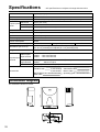
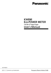
Specifications
· All specifications are subject to change without notice.
Product name
Liquid crystal projector
Model name
CP-S833W/E
Display system
3 sheets of liquid crystal panels, 3 primary color lights shutter system
2.3cm (0.9 inchs)
Panel size
Liquid crystal
TFT active matrix
Drive system
panel
Number of pixels 480,000 pixels (V600 X H800)
Lens
Zoom lens F=2.0 ~ 2.3
Lamp
UHP lamp 120W
Speaker
1W+1W (stereo)
Power supply
AC100 ~ 120V, 2.6A/AC220 ~ 240V, 1.3A
Power consumption
200W
Usable temperature range
32 ~ 95°F
Dimensions (W X H X D)
9.4" X 4.8" (including foot adjuster) X 12.6" (including lens).
9.4" X 5.2" (excluding foot adjuster) X 13.2" (excluding lens).
Weight
11.9 lbs.
Video signal
input terminal
Input/Output
terminal
RGB input/output
signal terminal
f=38 ~ 50mm
Storage Temperature range
-4 ~ 140°F
S VIDEO : Mini DIN4-pin terminal
VIDEO : RCA Jack terminal
AUDIO : RCA Jack terminal
RGB signal : D-sub 15pin shrink terminal (Female)
AUDIO
: Stereo mini jack
Control terminal D-sub 15pin shrink terminal (Male)
Remote control
POWER code
1
3 (CP-S833W)
2 (CP-S833E)
2
1
Accessories
BATTERIES LR6
RGB cable
Dimension diagram
12.6
All dimensions shown in inches.
0.6
32
(0.4)
4.8
2.9
9.4
MAC adaptor
Video/Audio cable
Mouse cable
Operating guide
1
1
3
1