1
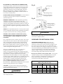
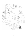
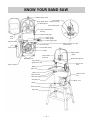
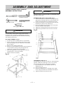
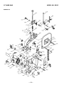
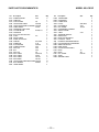
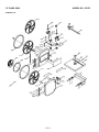
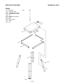
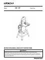
Model
CB 13F
Band Saw
INSTRUCTION MANUAL AND SAFETY INSTRUCTIONS
WARNING
Improper and unsafe use of this power tool can result in death or serious bodily injury!
This manual contains important information about product safety. Please read and understand
this manual before operating the power tool. Please keep this manual available for others before
they use the power tool.
TABLE OF CONTENTS
SECTION
Page
Products Specifications .......................................................... 3
Safety ...................................................................................... 4
Accessories and Attachments ............................................... 7
Carton Contents ..................................................................... 7
Know Your Band Saw ............................................................ 9
Glossary of Terms ................................................................. 10
SECTION
Page
Assembly and Adjustments ................................................. 11
Operation ............................................................................... 17
Maintenance .......................................................................... 20
Troubleshooting Guide ......................................................... 21
Parts List ................................................................................ 23
HITACHI AUTHORIZED SERVICE CENTERS
Service under this warranty is available from Hitachi Koki U.S.A., Ltd. at :
IN THE U.S.A.
IN CANADA
6395 Kestrel Road Mississauga, ON L5T 1Z5
3950 Steve Reynolds Blvd. Norcross, GA 30093
9409 Owensmouth Ave. Chatsworth, CA 91311
OR CALL: (800) 546-1666 for a service center nearest you. OR CALL: (800) 970-2299 for a service center nearest you.
— 2—
WARNING
Some dust created by power sanding, sawing, grinding, drilling and other construction activities contains chemicals
known to the state of California to cause cancer, birth defects or other reproductive harm. Some examples of these
chemicals are:
• Lead from lead-based paints
• Crystalline silica from bricks, cement and other masonry products
• Arsenic and chromium from chemically treated lumber
Your risk from these exposures varies, depending on how often you do this type of work. To reduce your exposure to
these chemicals, work in a well-ventilated area and work with approved safety equipment such as dust masks that are
specially designed to filter out microscopic particles.
PRODUCT SPECIFICATIONS
MOTOR
Power source ........................ 120 V, AC, 60 HZ, 7AMPS.
Speeds Low .......................... 1410 F.P.M
(Feet per minute)
High ......................... 2600 F.P.M
Horsepower .......................... 1HP(Max. Developed)
DRIVE BELT
A 26
Cutting Capacity
Throat .................................... 12”
Height .................................... 5”
Blade
Width ..................................... 1/8”, 1/4”, 3/8”, 1/2”
Length ................................... 80”
Table
Size ........................................ 13” x 13”
Tilt .......................................... 0° Left –– 45° Right
DUST COLLECTION ....................... Yes
NET WEIGHT .................................. 145.5 LB (66.0Kg.)
WARNING
To avoid electrical hazards, fire hazards, or damage to the
tool, use proper circuit protection.
Use a separate electrical circuit for your tools.
Your Band Saw is wired at the factory for 120V operation.
Connect to a 120V, 15 AMP branch circuit and use a 15
Amp time delay fuse or circuit breaker. To avoid shock or
fire, replace power cord immediately if it is worn, cut or
damaged in any way.
—3—
SAFETY
12. ALWAYS WEAR EYE PROTECTION. Any Band Saw
can throw foreign objects into the eyes that could
cause permanent eye damage. ALWAYS wear Safety
Goggles (not glasses) that comply with ANSI Safety
standard Z87.1 Everyday eyeglasses have only
impact–resistance lenses. They ARE NOT safety
glasses. Safety Goggles are available at HITACHI.
NOTE: Glasses or goggles not in compliance with
ANSI Z87.1 could cause serious injury.
GENERAL SAFETY INSTRUCTIONS
BEFORE USING THE BAND SAW
Safety is a combination of common sense, staying alert
and knowing how to use this Band Saw.
WARNING
To avoid mistakes that could cause serious injury, do not
plug the Band Saw in until you have read and understood
the following:
1.
READ and become familiar with the entire Operator’s
Manual. LEARN the tool’s application, limitations and
possible hazards.
13. WEAR A FACE MASK OR DUST MASK. Sawing
operation produces dust.
14. SECURE WORK. Use clamps or a vise to hold work
when practical. It’s safer than using your hand and it
frees both hands to operate tool.
2.
KEEP GUARDS IN PLACE and in working order.
15. DISCONNECT TOOLS before servicing; when
changing accessories such as blades, bits, cutters, and
the like.
3.
REMOVE ADJUSTING KEYS AND WRENCHES.
Form the habit of checking to see that keys and
adjusting wrenches are removed from the tool before
turning ON.
16. REDUCE THE RISK OF UNINTENTIONAL STARTING.
Make sure switch is in OFF position before plugging in.
4.
KEEP WORK AREA CLEAN. Cluttered areas and
benches invite accidents.
5.
DON’T USE IN DANGEROUS ENVIRONMENT.
Don’t use power tools in damp or wet locations, or
expose them to rain. Keep work area well lighted.
6.
KEEP CHILDREN AWAY. All visitors should be kept a
safe distance from work area.
7.
MAKE WORKSHOP CHILD PROOF with padlocks,
master switches, or by removing starter keys.
8.
DON’T FORCE THE TOOL. It will do the job better and
safer at the rate for which it was designed.
9.
USE THE RIGHT TOOL. Do not force tool or
attachment to do a job for which it was not designed.
17. USE RECOMMENDED ACCESSORIES. Consult the
Operator’s Manual for recommended accessories.
The use of improper accessories may cause serious
injury.
18. NEVER STAND ON TOOL. Serious injury could occur
if the tool is tipped or if the cutting tool is
unintentionally contacted.
10. USE PROPER EXTENSION CORD. Make sure your
extension cord is in good condition. When using an
extension cord, be sure to use one heavy enough to
carry the current your product will draw. An
undersized cord will result in a drop in line voltage
and in loss of power that will cause the tool to
overheat. The table on page 7 shows the correct size
to use depending on cord length and nameplate
ampere rating. If in doubt, use the next heavier gauge.
The smaller the gauge number, the heavier the cord.
11. WEAR PROPER APPAREL. Do not wear loose clothing,
gloves, neckties, rings, bracelets, or other jewelry that
may get caught in moving parts. Non-slip footwear is
recommended. Wear protective hair covering to
contain long hair.
19. CHECK FOR DAMAGED PARTS. Before further use of
the tool, a guard or other part that is damaged should
be carefully checked to determine that it will operate
properly and perform its intended function – check for
alignment of moving parts, binding of moving parts,
breakage of parts, mounting, and any other conditions
that may affect its operation. A guard or other part
that is damaged should be properly repaired or
replaced.
20. NEVER LEAVE TOOL RUNNING UNATTENDED.
TURN POWER “OFF”. Don’t leave tool until it comes
to a complete stop.
21. DON'T OVERREACH. Keep proper footing and balance
at all times.
22. MAINTAIN TOOLS WITH CARE. Keep tools sharp and
clean for best and safest performance. Follow
instructions for lubricating and changing accessories.
23. DO NOT use power tools in the presence of flammable
liquids or gases.
—4—
24. DO NOT OPERATE the tool if you are under the
influence of any drugs, alcohol or medication that
could affect your ability to use the tool properly.
14. CUT only one work-piece at a time. Make sure the
table is clear of everything except the work-piece and
its guides before you turn the saw on.
25. ALWAYS operate the band saw in a well-ventilated
area and provide for proper dust removal. Use dust
collection systems whenever possible. Dust generated
from certain materials can be hazardous to your
health.
15. ALWAYS WATCH the saw run before each use. If
there is excessive vibration or unusual noise, stop
immediately. Turn the saw OFF. Unplug it
immediately. Do not start the saw again until the
problem has been located and corrected.
16. TO FREE any jammed material, turn the switch OFF.
Remove the switch key and unplug the saw. Wait for
all moving parts to stop before removing jammed
material.
SPECIFIC SAFETY INSTRUCTIONS FOR
BAND SAWS
1.
TO AVOID INJURY from unexpected movement, make
sure the saw is on a firm, level surface, properly
secured to prevent rocking. Make sure there is
adequate space for operating. Bolt the saw to a
support surface to prevent slipping, walking, or sliding
during operation.
2.
TURN the saw OFF and unplug the saw before moving
it.
3.
USE THE CORRECT size and style of blade.
4.
USE blades rated at 2700 FPM or greater.
5.
MAKE SURE the blade teeth point down and towards
the table.
6.
BLADE GUIDES, SUPPORT BEARINGS, AND BLADE
TENSION must be properly adjusted to avoid
accidental blade contact and to minimize blade
breakage. To maximize blade support, always adjust
the upper blade guide and blade guard so that it is 1/8
inch above the work-piece.
7.
TABLE LOCK HANDLE should be tight.
8.
USE EXTRA CAUTION with large, very small or
awkward work-pieces.
9.
USE EXTRA SUPPORTS to prevent work-pieces from
sliding off the table top. Never use another person to
support the work-piece.
17. DON’T LEAVE the work area until all moving parts are
stopped. To child-proof the workshop, shut OFF the
power to master switches and remove the switch key
from the band saw. Store it in a safe place, away from
children.
WARNING
For your own safety, read the entire instruction manual
before operating the band saw.
1. Wear eye protection.
2. Do not wear gloves, necktie, or loose clothing.
3. Make sure the saw is on a firm level surface and
properly secured.
4. USE ONLY THE RECOMMENDED ACCESSORIES.
5. Use extra caution with very large, very small, or
awkward work-pieces.
6. Keep hands away from the blade at all times to
prevent accidental injury.
7. Do not remove jammed cutoff pieces until the blade
has stopped.
8. Maintain proper adjustment of blade tension, blade
guides and thrust bearings.
9. Adjust upper guide to just clear the work-piece.
10. Hold the work-piece firmly against the table.
ELECTRICAL REQUIREMENTS
POWER SUPPLY AND MOTOR SPECIFICATIONS
WARNING
10. WORK-PIECES must be secured so they don’t twist,
rock, or slip while being cut.
11. PLAN intricate and small work carefully to avoid
pinching the blade. Avoid awkward operation and
hand positions to prevent accidental contact with the
blade.
12. SMALL PIECES should be secured with jigs or fixtures.
Do not hand hold pieces that are so small your fingers
are under the blade guard.
13. SUPPORT round work properly (with a V-block or
clamped to the miter gauge) to prevent it from rolling
and the blade from biting.
To avoid electrical hazards, fire hazards, or damage to the
tool, use proper circuit protection. Use a separate
electrical circuit for your tools. Your saw is wired at the
factory for 120V operation. Connect to a 120V, 15 Amp
circuit and use a 15 Amp time delay fuse or circuit
breaker. To avoid shock or fire, if power cord is worn or
cut, or damaged in any way, have it replaced immediately.
GROUNDING INSTRUCTIONS
WARNING
This tool must be grounded while in use to protect the
operator from electrical shock.
—5—
IN THE EVENT OF A MALFUNCTION OR BREAKDOWN,
grounding provides a path of leas t res is tance for electric
current and reduces the ris k of electric s hock. T his tool is
equipped with an electric cord that has an equipm entgrounding conductor and a grounding plug. T he plug
M U S T be plugged into a m atching receptacle that is
properly ins talled and grounded in accordance with A LL
local codes and ordinances .
Fig. A
3-Prong Plug
G rounding Prong
DO NOT MODIFY THE PLUG PROVIDED. If it will not fit the
receptacle, have the proper receptacle ins talled by a
qualified electrician.
Properly G rounded
3-Prong R eceptacle
Fig. B
IMPROPER CONNECTION of the equipm ent-grounding
conductor can res ult in ris k of electric s hock. T he
conductor with green ins ulation (with or without yellow
s tripes ) is the equipm ent-grounding conductor. If repair or
replacem ent of the electric cord or plug is neces s ary, DO
N OT connect the equipm ent-grounding conductor to a live
term inal.
G rounding Lug
M ake S ure T his
is Connected to a
K nown G round
2-Prong
R eceptacle
A dapter
CHECK with a qualified electrician or s ervice pers on if you
do not com pletely unders tand the grounding ins tructions ,
or if you are not s ure the tool is properly grounded.
USE ONLY 3-wire extension cords that have 3-prong
grounding plugs and 3-pole receptacles that accept the
tool's plug. Repair or replace damaged or worn cord
immediately.
T his band s aw is for indoor us e only. Do not expos e to
rain or us e in dam p locations
GUIDELINES FOR EXTENSION CORDS
U s e a s eparate electrical circuit for your tools . T his circuit
m us t not be les s than # 12 wire and s hould be protected
with a 15 A m p tim e delay fus e. B efore connecting the
m otor to the power line, m ake s ure the s witch is in the
OFF pos ition and the electric current is rated the s am e as
the current s tam ped on the m otor nam eplate. R unning at
a lower voltage will dam age the m otor.
T his tool is intended for us e on a circuit that has a
receptacle like the one illus trated in Figure A .
s hows a 3-prong electrical plug and receptacle that has a
grounding conductor. If a properly grounded receptacle is
not available, an adapter (Figure B ) can be us ed to
tem porarily connect this plug to a 2-contact ungrounded
receptacle. T he adapter (Figure B ) has a rigid lug extending
from it that M U S T be connected to a perm anent earth
ground, s uch as a properly grounded receptacle box.
T HE T E N POR A R Y A DA PT E R S HOU LD B E U S E D ON LY
U N T IL A PR OPE R G R OU N DE D PU T LE T CA N B E
IN S T A LLE D B Y A QU A LIFIE D E LE CT R ICIA N . T he Canadian
E lectrical Code prohibits the us e of adapters .
CAUTION: In all cas es , m ake certain the receptacle is
properly grounded. If you are not s ure, have a qualified
electrician check the receptacle.
WARNING
WARNING
USE PROPER EXTENSION CORD. M ake s ure your
extens ion cord is in good condition. W hen us ing an
extens ion cord, be s ure to us e one heavy enough to carry
the current your product will draw. A n unders ized cord
will caus e a drop in line voltage, res ulting in los s of power
and caus e overheating. T he table below s hows the correct
s ize to us e depending on cord length and nam eplate
am pere rating. If in doubt, us e the next heavier gauge.
T he s m aller the gauge num ber the heavier the cord.
Be sure your extension cord is properly wired and in good
condition. A lways replace a dam aged extens ion cord or
have it repaired by a qualified pers on before us ing it.
Protect your extens ion cords from s harp objects ,
exces s ive heat and dam p or wet areas .
MINIMUM GAUGE FOR EXTENSION CORDS (AWG)
(When using 120 Volt only)
A m pere R ating
N ot
M ore T han M ore T han
0
6
6
10
10
12
12
16
T his tool is for indoor us e only. Do not expos e to rain or
us e in dam p locations .
—6—
T otal length in feet
25'
18
18
16
14
50'
16
16
16
12
100'
150'
16
14
14
12
14
12
N ot A pplicable
ACCESSORIES AND ATTACHMENTS
RECOMMENDED ACCESSORIES
䢇
WARNING
䢇
To avoid injury:
䢇 Use only accessories recommended for this band saw.
䢇 Follow instructions that accompany accessories. Use
of improper accessories may cause hazards.
Use only accessories designed for this band saw to
avoid injury from thrown broken parts or workpieces.
Do not use any accessory unless you have completely
read the instruction or operator’s manual for that
accessory.
ITEM
Blade width: 1/8”,1/4”,3/8”,1/2”
Blade length: 80”
CARTON CONTENTS
UNPACKING AND CHECKING CONTENTS
TABLE OF LOOSE PARTS
Carefully unpack the band saw and all its parts, and
compare against the illustration following. Place the saw
on a secure surface and examine it carefully.
ITEM
WARNING
䢇
䢇
䢇
To avoid injury from unexpected starting, do not plug
the power cord into a power source receptacle during
unpacking and assembly. This cord must remain
unplugged whenever you are assembling or adjusting
the saw.
Although compact, this saw is heavy. To avoid back
injury, get help whenever you have to lift the saw.
If any part is missing or damaged, do not plug the
band saw in until the missing or damaged part is
replaced, and assembly is complete.
DESCRIPTION
BAND SAW:
A.
Band saw with motor
B.
Table with extension wing
C.
Trunnion support bracket
D.
Miter gauge
E.
Sawdust port
F.
Power cord hooks
Foot pads
G.
Hex. Bolt & nuts
H.
Hex. Bolt
I.
Knobs
J.
Hex. Key
K.
Screws
L.
Long hex. Bolt
M.
Hex. Nuts
N.
Large washers
LEG STAND:
O.
Leg stand top plate
P.
Short lower brackets
Q.
Long lower brackets
R.
Legs
S.
Bag:
Carriage bolts
Hex. Nuts
Washers
—7—
QUANTITY
1
1
1
1
1
2
4
1
4
2
1
2
1
4
8
1
2
2
4
32
32
32
UNPACKING YOUR BAND SAW
B
C
E
D
G
J
H
A
K
L
F
I
O
N
M
P
Q
R
S
—8 —
KNOW YOUR BAND SAW
Blade tension knob
Upper blade wheel
Lower blade
support bearing
Blade guard
Lower blade guide
Upper blade support
bearing
Upper blade guide
Upper
cover
Table insert
Miter gauge
Table aligning pin
ON/OFF switch
Tilt bevel scale
Table removed for clarity
of illustration
Lower blade wheel
Lower cover
V-Belt
Mounting holes
Upper blade
guide lock knob
Upper blade
guide rod
Blade tension
gauge
Blade tracking knob
Power cord
wrap
Motor pulley
Blade
Miter slot
Table
V-Belt tension
lock
Table trunnion
Table lock plate
Sawdust port
Motor cord
Motor
Stand top table
Leg stand
—9—
GLOSSARY OF TERMS
BAND SAW TERMS
BLADE GUIDES — Support the blade and keep it from
twisting during operation. Blade guides must be adjusted
when blade is changed or replaced.
BLADE TENSION KNOB — Controls the amount of blade
tension when changing blades.
KERF — The material removed by the blade in a through
cut, or the slot produced by the blade in a non-through or
partial cut.
LEADING EDGE — The front edge of the workpiece
pushed into the cutting tool first.
MITER CUT — An angle cut made across the width of a
workpiece.
BLADE TRACKING KNOB — Adjusts blade position so
blade always runs in the center of the wheel.
RESAW — A cutting operation to reduce the thickness of
the workpiece to make thinner workpiece.
ON/OFF SWITCH — Has a built-in child safety lock. To lock
the switch in the OFF position, remove the switch key
from the switch.
RESIN — A sticky sap that has hardened.
RIPPING CUT — A cutting operation along the length of
the workpiece.
RELIEF CUT —Removal of waste material by a cut from
the outside edge, allowing easier cutting of intricate
curves.
R.P.M. — Revolutions per minute. The number of turns
completed by a spinning object in one minute.
SAWDUST PORT — Helps keep the machine free from
sawdust. The sawdust port makes an excellent hook-up
for a wet/dry vacuum.
SAW BLADE PATH — The area of the workpiece or table
top directly in line with the travel of the blade or the part
of the workpiece that will be cut.
TABLE LOCK KNOB — Locks the table in place.
SET — The distance between two saw blade teeth tips,
that are bent outward in opposite directions to each other.
The further apart the tips are, the greater the set.
TILT (BEVEL) SCALE — Shows the degree the table is
tilted for bevel cutting.
UPPER GUIDE LOCK KNOB — Locks the upper slide. Use it
after adjusting the upper guide assembly to make sure
upper blade guide just clears workpiece before cutting.
Upper guide lock knob must be tightened before the band
saw is turned on.
TRAILING EDGE — The workpiece edge last cut by the
blade.
WORKPIECE — The item being cut. The surfaces of a
workpiece are commonly referred to as faces, ends and
edges.
WOODWORKING TERMS
WORKTABLE — The surface on which the workpiece
rests while performing a cutting or sanding operation.
BEVEL CUT — An angle cut made through the face of a
workpiece.
COMPOUND CUT — A simultaneous bevel and miter cut.
CROSSCUT — A cut made across the width of the
workpiece.
Leading Edge
F.P.M. — Feet per minute. Used in reference to the surface
speed of the saw blade.
Kerf
Relief cut
Sawblade
Path
Surface
FREE HAND — Performing a cut without using a fence
(guide), hold-down or other proper device to prevent the
workpiece from twisting during the cutting operation.
GUM — A sticky sap-based residue from wood products.
HEEL — Misalignment of the blade.
— 10 —
Workpiece
Trailing Edge
ASSEMBLY AND ADJUSTMENT
ESTIMATED ASSEMBLY TIME 35~50MINUTES
ASSEMBLY INSTRUCTIONS
WARNING
Although compact, this saw is heavy. To avoid back injury,
get help to lift the saw.
Philips screwdriver
Combination square
Adjustable wrench
Straight edge
ASSEMBLE BAND SAW TO LEG STAND (Fig. B)
1. Lift the saw body (1) and place on the leg stand (2),
aligning the mounting holes (3) of the saw base with
the four mounting holes of the leg stand top plate.
2. Attach the band saw to the stand with four long hex
head bolts (4) and four flat washers (5).
3. Place a flat washer (5) and hex nut (6) on each bolt
from the underside. Hand tighten.
4. Tighten all mounting bolts and nuts with a wrench.
5. Tighten all leg stand bolts and nuts with a wrench.
Feeler gauge - size 0.02
Fig. B
WARNING
1
For your safety, never connect plug to power source
receptacle until all assembly and adjustment steps are
completed, and you have read and understood the safety
and operating instructions.
4
5
3
2
LEG STAND ASSEMBLY (Fig. A)
1. Lay the top plate (1) upside down on a flat surface.
2. Attach a leg (2) to the outside of the stand top plate
with four carriage bolts (3), washers (4), and nuts(5).
Do not tighten.
3. Repeat for the remaining three legs.
4. Attach two long brackets (6) and two short brackets (7)
to the inside for the legs, using carriage bolts (3),
washers (4), and nuts (5). Do not tighten.
5. Place the leg pads (8) on each leg and turn the leg
stand upright on a firm level surface.
6. Adjust the stand for stability.
Fig. A
5
6
11
12
1
54
2
7
3
THE SAWDUST PORT (Fig. C)
The sawdust port has a 2-1/2"(O.D) /2-1/4"(I.D) diameter
opening, suitable for attaching to a wet / dry vacuum
hose, to help keep the work area free of sawdust.
1. Remove the bolts (1) and washers (2) from the
sawdust port (3).
2. Open the wheel cover (4).
3. Attach the sawdust port to the edge of the wheel
cover, using the same hex. head bolts and washers.
4. Tighten the bolts and close the cover.
6
8
— 11 —
Fig. C
6.
7.
8.
4
3
1
9.
Turn the table right side up.
Remove the table insert (13) from the table.
Guide the table slot (14) over the saw table and
rotates 1/4 turn, so the slot is perpendicular to the
blade.
Placing the scale lock knob bolts (10) through the
trunnion bracket holes (15) as shown, lower the table
onto the trunnion bracket.
Fig. E
13
14
2
10
ASSEMBLE THE BAND SAW TABLE (Fig. D, E, F)
Mounting the trunnion support bracket (Fig. D)
1. Remove the two hex head bolts (1) and washers (2),
located on the lower band saw housing.
2. Place the trunnion support bracket (3) on the saw
body, as shown, aligning the mounting holes.
3. Place the washers on the hex head bolts, and insert
into the threaded holes, through the bracket and saw
body. Tighten.
4. Thread a nut (4) onto the table stop bolt (5) and screw
bolts into the rear tab (6) on the trunnion support
bracket.
5. Tighten the nut down onto the bracket tab.
Fig. D
15
13. Place a lock knob (16) on each scale knob bolt adjust
the table by aligning the zero scale mark to the scale
pointer (17), and tighten the knob.
14. Replace the table insert (13), aligning the indents.
15. Place the table aligning pin (18) in the hole at the front
of the table, and tighten.
Fig. F
13
5
4
1
2
6
3
17
16
— 12 —
18
INSTALLING AND REMOVING THE BLADE(Fig.G)
WARNING!
To avoid injury from accidental starting, always turn the
switch OFF and remove the plus from the power source
before moving, replacing, or adjusting the blade.
Removing
1. Loosen the blade tension by turning the blade tension
knob (1) counterclockwise.
2. Remove the table insert (2) and the table aligning
pin (3) from the table.
Unlock the lock knobs (12) under the table. Unfasten
the screw (13) at the right of extension tube and
remove the extension table from the table.
3. Open up wheel cover door (4).
4. Loosen the two Phillips screws (5) and remove the
upper blade guard (6).
5. Release the lock knobs (12) under the table, then
remove the screw (13) at the right of extension tube
and the extension table.
6. Remove the blade (7) from the upper and lower blade
guides (8).
7. Carefully pull the blade from the side slot (9) and from
the wheels (10).
8. Swing the left side of the blade toward you, turning
the blade so it will fit through the slot (11) in the table,
and remove.
Fig. G
Installing
1. Make sure the blade tension knob (1) turned
counterclockwise until it stops.
2. Remove old blade as explained in "Removing".
3. Guide the new blade teeth are pointing forward and
down.
NOTE: To avoiding lifting the workpiece, the blade
teeth must point downward toward the table.
4. Swinging the left side off the blade away and back,
place the blade on the upper and lower wheels (10).
5. Place the blade carefully between the upper and lower
blade guides (8).
6. Slide the blade into the slot (9) at the left of the
wheels, and make sure the blade is positioned at the
middle of the wheels.
7. Turning the blade tension knob (1) clockwise, tighten
the tension until the blade is tight on the wheels.
8. Replace the table insert (2) and the table aligning pin (3).
Install the extension table and fasten the screw (13) at
the right of extension tube. Lock the lock knobs (12)
under the table.
9. Adjust the blade tracking and tension properly (See
ADJUSTMENT INSTRUCTIONS section) before
operation the band saw.
WARNING
1
To avoid injury, the blade tension, tracking, and upper and
lower guides and bearings must be properly adjusted
before operating the band saw. (See ADJUSTMENT
INSTRUCTIONS section)
10
MITER GAUGE (Fig. H)
A miter gauge (1) is supplied with your band saw to be
used in the table slot (2) on the right side of the blade. The
miter gauge can be tilted 0 to 45 deg. right or left to maintain
an accurate angle for your workpiece. A bracket is
provided on the leg stand for convenient miter gauge
storage.
6
5
8
9
7
4
2
11
Fig. H
1
3
8
2
10
13
12
WARNING
Before operation always make sure the blade is in center
of table insert slot.
— 13 —
INSTALL POWER BCORD BRACKETS (Fig. I)
1. Power cord brackets (1) are provided for convenient
cord storage. Attach the power cord brackets to the
back of the saw body, as shown, with two Phillips
head screws (2). Tighten.
2. Wrap the power cord onto the brackets when the band
saw is not in use, to prevent damage to the cord.
Fig. I
2
ADJUSTING THE 90° TABLE STOP (Fig. K)
1. Loosen the table lock knobs (2) and tilt the table to the
right.
2. Loosen the nut (4) on the table stop bolt (5) and lower
the stop bolt as far as possible.
3. Tilt the table until rests on the stop bolt.
4. Place a combination square (6) on the table with the
heel of the square against the saw blade
5. Adjust the tilt of the table left or right until it is 90° to
the blade. Male sure there is no space between the
square and the blade. Tighten the table lock knobs.
6. Adjust the table stop bolt up until it touches the table.
7. Loosen the lock knobs and see that the table is resting
on the stop bolt.
8. Check the square to make sure the table is still square
to the blade. If not, readjustment the stop bolt.
9. When the adjustment is accurate at 90°, align the
pointer (7) to 0° the scale (8)
Fig. K
1
5
6
ADJUSTMENT INSTRUCTIONS
WARNING
To avoid injury, turn the switch OFF and unplug the band
saw from the power source before making any
adjustments.
8
TABLE ADJUSTMENTS (Fig. J, K)
Tilting the table (Fig. J)
The band saw table (1) tilts 0° to 45° right
1.
2.
3.
7
Loosen both table lock knobs (2) underneath the table.
Tilt the table to the desired angle on the scale (3)
underneath the table.
Tighten the two table lock knobs.
1
Fig. J
2
3
2
— 14 —
4
5.
BLADE TENSION(FIG. L)
WARNING
6.
To avoid injury, turn the switch OFF and disconnect the
saw from the power source before making any
adjustments.
NEVER make tension adjustments with the machine
running.
If the blade moves toward the front of the wheel, turn
the tracking knob (5) on the rear of the band saw
clockwise. This tilts the top of the wheel and moves
the blade toward the center.
If the blade moves toward the back edge, turn the
tracking knob counterclockwise, moving the blade
toward the center.
NOTE: Turn the tracking knob SLIGHTLY to make
blade tracking adjustments.
Fig. M
The gauge (1) on the bracket (2) at the rear of the upper
wheel housing indicates the proper tension for the various
blade widths.
1.
2.
3.
Set the blade tension gauge to correspond with the
width of the blade in use.
Turn the blade tension knob (3) clockwise, raising the
upper wheel to tighten the blade. Turn the knob
counterclockwise to lower the upper wheel, loosening
the blade.
As you become familiar with the saw, you may want
to change the tension settings.
NOTE: Changes in blade width and type of material
being cut will have an effect on the blade tension. Too
much or too little tension could break the blade. When
the band saw is not in use, relax the blade tension.
5
4
3
2
Fig. L
1
3
UPPER BLADE GUIDE ASSEMBLY (FIG. N)
2
WARNING
1
To avoid injury, turn the switch OFF and disconnect the
saw form the power source before making any
adjustments.
NEVER make adjustments with the machine running;
1.
2.
Loosen the lock knob (1) and move the blade guide
assembly (2) up or down to 1/8” above the workpiece.
Tighten the lock knob.
Fig. N
BLADE TRACKING (FIG. M)
WARNING
1
To avoid injury, turn the switch OFF and disconnect the
saw from the power source before making any
adjustments.
NEVER make tension adjustments with the machine
running.
1.
2.
3.
4.
The blade (1) must be tensioned properly before
adjusting the tracking.
Open blade (1) the upper cover.
Move the blade guides (2) and support bearings (3)
away from the blade, if necessary. See page 15 for
bearing and guide adjustment.
Rotate the wheel (4) slowly forward by hand, and
check the position of the blade on the wheel. The
blade should remain centered on the wheel as it turn.
— 15 —
2
UPPER BALDE GUIDES AND BLADE SUPPORT BEARING
(Fig. O, P)
Fig. P
WARNING
䢇
The blade guard has been removed for clarity of
illustration. To avoid injury never operate the band
saw without all guards in place and in working order.
䢇 To avoid injury, turn the switch OFF and disconnect
the saw from the power source before making any
adjustments. NEVER make adjustments with the
machine running.
NOTE: Make sure the blade is tensioned and tracking
properly. Adjust the blade guides and support bearing
after each blade tension and tracking adjustment. When
the upper blade guides and support bearings are adjusted,
the lower guides and bearing should also be adjusted.
Blade guides (Fig. O)
1. Make sure the blade is tensioned and tracking
properly.
2. Loosen the front hex socket screws (1) with a hex
wrench.
3. Move the guides (2) as close to the blade (3) as
possible without pinching it.
4. Using a feeler gauge, make sure the space between
each guide and the blade measures 0.02”. (the
thickness of a dollar bill)
5. Tighten the hex socket screws.
6. Loosen the side hex socket screw (4) by turning
counterclockwise.
7. Move the blade guides bracket shaft (5) in or out until
the guides are at least 1/32” behind the blade teeth.
8. The guides must remain behind the blade teeth during
operation to prevent damage to the saw blade.
9. Tighten the hex socket screw.
1/64”
6
7
8
LOWER BLADE GUIDES AND SUPPORT BEARING
WARNING
To avoid injury, turn the switch OFF and disconnect the
saw from the power source before making any
adjustments.
NEVER make adjustments with the machine running.
NOTE: Make sure the blade is tensioned and tracking
properly.
The lower blade guides and support bearings should
always be adjusted after the blade is tensioned, the
tracking is adjusted, and the upper blade guides and
upper support bearings are properly adjusted.
Blade guides (Fig. Q)
1. Loosen both front hex socket screws (1) with a hex
wrench.
2. Move the guides (2) as close to the sides of the blade
(3) as possible without pinching it.
3. Using the feeler gauge, measure the spaces between
the guide and the blade. Adjust to 0.02”
4. Tighten the hex screws.
5. Loosen the side hex socket screw (4). Move the guide
support bracket (5) in or out until the guides are at
least 1/32” behind the saw teeth. Tighten the screw.
Fig. O
2
1
3
3
Fig. Q
4
2
8
5
3
1
2
Support bearing (Fig. P)
10. Loosen the bearing hex socket screw (6).
11. Move the support bearing shaft (7) in or out, until the
bearing (8) is 1/64” behind the blade.
12. Tighten the hex socket screw (6).
NOTE: The blade support learning prevent the blade
from moving back too far and damaging the saw teeth
setting.
— 16 —
1
5
4
Support bearing (Fig. R)
6. Loosen the bearing hex socket screw (7) with the hex
wrench.
7. Move the blade support bearing shaft (8) in or out
until the support beating (9) is 1/64 " behind the saw
blade.
8. Tighten the beating hex socket screw.
Fig. R
1. Place a straight edge in the front groove of both
pulleys, behind the blade wheel.
2. Turn the hex socket screw (1) in the side of the motor
pulley (2) to loosen the pulley on the shaft.
3. Adjust the motor pulley in or out on the motor shaft
(3) to align the edges of the two pulleys.
4. When aligned, tighten the hex socket screw on the
side of the motor pulley.
Fig. S
2
7
3
9
8
1
MOTOR
Pulley alignment (Fig. S)
The pulley alignment is adjusted properly at the factory
and should not need readjustment.
If adjustment is needed , or the belt needs replacing:
3
1
OPERATION
BASIC SAW OPERATIONS
Fig. T
ON / OFF SWITCH (Fig. T)
The keyed switch is intended to prevent unauthorized use
of the band saw.
1. To turn the band saw ON insert the yellow key (1) into
the key slot in the center of the switch.
2. Push the key firmly into the slot, then push switch to
the ON position to start the band saw.
3. To turn the band saw OFF push the switch to the
down position.
4. Remove the yellow switch key, when the saw has
come to a complete stop, by gently pulling it outward.
1
WARNING
Remove the switch key whenever the saw is not in use.
Place it in a safe place and out of reach of children.
USING THE TABLE EXTENSION (Fig. T-1)
NOTE:
A. For ripping 5-3/4"~ 7-1/2" workpiece, the extension
fence has to be installed in the IN-RIP position (Fig. P).
Remove the lock handles (1) and fence. Place the
fence on extension table as shown. Raise the fence to
a position that just clears the table surface and secure
in place using lock handles (1) for IN-RIP position.
B. For ripping 7-1/2 "~ 12 " workpiece, the extension fence
has to be installed in the OUT-RIP position.
— 17 —
1. Release both cam locking levers.
2. Slide the table extension on the side your workpiece
will be needing support, and tighten both cam locking
levers.
Slide the extension out until the correct measurement is
displayed on the tube scale. GENERAL CUTTING
Fig. T-1
CUTTING CURVES
When cutting curves, carefully turn the workpiece so the
blade follows without twisting, If the curve is so sharp that
you repeatedly back up and cut new kerf, use a narrower
blade, or a blade with more set (teeth further apart).
When a blade has more set, the workpiece turns easier
but the cut is rougher.
When changing a cut, do not withdraw the workpiece
from the blade. The blade may get drawn off the wheels.
To change a cut, turn the workpiece and saw out through
the scrap material area.
When cutting long curves, make relief cuts as you go
along.
WARNING
For your safety, read and understand all GENERAL and
SPECIFIC SAFETY INSTRUCTIONS on pages 4-6 before
using the band saw.
Operating band saws involves a certain amount of hazard.
Before attempting regular work, use scrap lumber to check
the settings and to get the feel of operating the band saw.
Read instructions and plan your work before cutting a
workpiece.
CIRCLE CUTTING (Fig. U)
1. Adjust the guide assembly to 1/8 " above the
workpiece.
2. Use both hands while feeding the work into the blade.
Hold the workpiece firmly against the table. Use
gentle pressure. Do not force the work, ALLOW the
blade to cut.
3. The smallest diameter circle that can be cut is
determined by the width of the blade. For example, a
1/4 " wide blade will cut a minimum diameter of
approximately 1-1/2 ".
Fig. U
Do not turn the power ON until after you have made all
adjustments, checked that the guard is in place, and
turned the wheel by hand to make sure all parts work
properly. Always keep the guide assembly close to your
work, 1/8 "above the workpiece.
1/2 "D 1 "D
1/8" 3/16"
Do not force the workpiece, against the blade. Light
contact permits easier cutting and prevents unwanted
friction and heating of the blade.
Sharp saw blade need little pressure for cutting. Steadily
move the workpiece against the blade without forcing it.
To avoid twisting the blade, do not turn sharp comers,
saw around corners.
A band saw is basically a "curve-cutting " saw. It is not
capable of doing intricate inside cutting as can be done
with a scroll saw.
It is also used for straight line operations such as
crosscutting ripping , mitering, beveling, compound
cutting, and resawing.
WARNING
To avoid blade breakage, fire or other damage or injury,
NEVER use this band saw to cut ferrous metals.
1-1/2"D
1/4"
2"D
3/8"
Minimum
2-1/2 "D Circle Diameter
1/2"
Blade Width
BLADE SELECTION (FIG. V)
CAUTION: blade teeth are sharp. Use care when handling
a saw blade.
For longest wear and best cutting results, use the correct
blade thickness width, and temper for the type of material
you will cut.
When sawing small curves and delicate work, use narrow
blades. Otherwise, use the widest blade possible, For
cutting wood and similar materials with this bandsaw,
purchase blades in widths up to 1/2 ", and a length of 80 ".
Do not cut ferrous metals with this band saw.
— 18 —
Common causes of blade breakage:
䢇 Poor guide alignment and adjustment.
䢇 Forcing or twisting a wide blade around a short
radius.
䢇 Feeding too fast.
䢇 Dull teeth or not enough set.
䢇 Too much blade tension.
CHANGING SPEED SETTING (Fig. X)
WARNING
For longest wear and best cutting results, use the correct
blade thickness width, and temper for the type of material
you will cut.
When sawing small curves and delicate work, use narrow
blades. Otherwise, use the widest blade possible, For
cutting wood and similar materials with this bandsaw,
purchase blades in widths up to 1/2”, and a length of 80”.
Do not cut ferrous metals with this band saw.
Common causes of blade breakage:
䢇 Poor guide alignment and adjustment.
䢇 Forcing or twisting a wide blade around a short
radius.
䢇 Feeding too fast.
䢇 Dull teeth or not enough set.
䢇 Too much blade tension.
䢇 Setting top guide assembly too high above the
workpiece.
䢇 Lumpy or improperly finished braze or weld on the
blade.
䢇 Continuous running of blade when not cutting.
To avoid injury, turn the switch OFF and disconnect the
saw from the power source before making any
adjustments.
NEVER make adjustments with the machine running.
1. Loosen the belt tension by turning the tension lock
handle (6).
2. Open the lower wheel cover and reposition the V-belt (3).
A. Changing the speed from 1410 to 2600 FPM:
Remove the belt (3) from the band saw pulley (4)
first, and reposition in the saw pulley groove(1).
Next, remove the belt from the motor pulley (5)
and reposition in the motor pulley groove (2).
B. Changing the speed from 2600 to 1410 FPM:
Remove the belt (3) from the motor pulley (5) first,
and reposition in the motor pulley groove (2).
Remove the belt from the saw pulley (4) and
Reposition in the saw pulley groove (2).
3. Tighten the belt tension by turning the tension lock
handle (6).
NOTE: After readjusting belt position and belt tension,
check and readjust the settings for the blade tension
and tracking, guides and bearings (See ADJUSTMENT
section).
Fig. X
Fig. V
Operation
Recommended Blade Width
(Inches)
Cross Cutting
Mitering
Beveling
Compound Cutting
Circle Cutting
Curve Cutting
2
1/4, 3/8, 1/2
1/4, 3/8, 1/2
1/4, 3/8, 1/2
1/4, 3/8, 1/2
See Fig. U
1/8, 1/4
1
4
5
3
4
6
BLADE SPEED SELECTION (Fig. W)
This band saw has two speed settings:
1. 2600 F.P.M for normal operation.
2. 1410 F.P.M for operation requiring more control.
5
MOTOR
RECOMMENDED SPEEDS
Fig. W
SPEED
2600 F.P.M
1410 F.P.M
1
APPLICATION
BLADETYPE
1. Basic wood cutting 1.Skip tooth type
2. Resawing
2.Hook tooth type
3.Regular tooth blades
1. Intricate wood cutting
2. Veneers, tiles,
plastics
3. Nonterrous metals; 15 teeth per inch blades
brass. copper,
aluminum
2
WARNING
To avoid possible injury or damage, NEVER use this band
saw to cut ferrous metals.
CAUTION: When cutting nonferrous metals, metal
shavings can react with wood dust and start a fire. To
avoid this:
1. Disconnect any dust collecting hose from the band
saw.
2. Remove all traces of wood dust from inside the saw.
3. Remove all metal shaving from inside the saw
before sawing wood again.
— 19 —
MAINTENANCE
GENERAL MAINTENANCE
WARNING
WARNING
䢇
䢇
䢇
For your own safety, turn switch OFF and remove the
plug from power source receptacle before
maintaining, cleaning, adjusting, or lubricating your
band saw.
To avoid fire or toxic reaction, never use gasoline,
naphtha, acetone, lacquer thinner or similar highly
volatile solvents to clean the band saw.
To avoid eye injury from blowing debris, wear safety
goggles when blowing out sawdust.
To avoid injury, the blade tension, tracking, and upper and
lower guides and bearings must be properly adjusted
before operating the band saw. (See ADJUSTNEBT
INSTRUCTIOONS section)
Fig. Y
1
4
BAND SAW
Sawdust will accumulate under the table and base. This
could cause difficulty in the movement of the table when
setting up a band saw cut, and also cause a fire hazard.
Frequently blow out or vacuum up the sawdust.
Keep your band saw clean. Remove the sawdust from the
inside. Vacuum or blow out frequently.
Do not allow filth to build up on the table, the guides, or
the support bearings. Clean them with gum and pitch
remover.
NOTE: Do not immerse the support bearing in the gum
and pitch remover.
Put a thin coat of paste wax on the table so that the wood
slides easily while cutting.
TO INSTALL A NEW BELT (Fig. Y)
1. Open the lower wheel door.
2. Loosen the blade tension by turning the blade tension
lock knob (1).
3. Remove the blade from the lower blade wheel.
4. Loosen and remove the hex head blot (2) and flange
(3) on the lower blade wheel.
5. Remove the lower blade wheel.
6. Turn the belt tension handle (4) on the rear of the saw
housing to loosen the v-belt tension.
7. Remove the v-belt (5)
8. Check the alignment of the two pulleys.
9. If the edges of the two pulleys are not aligned, see:
ALIGN THE PULLEYS” in ADJUSTMENT section.
10. Place the new v-belt on the saw pulley and the motor
pulley. See OPERATION section “CHANGING SPEED
SETTINGS” on page for proper belt placement.
11. When positioned properly, tighten the v-belt tension
by turning the tension lock handle.
NOTE: The pulley belt is properly tensioned when there is
1/2”deflection if pressed in the center between the
pulleys.
12. Replace the blade wheel. Push the wheel on firmly
until it is touching the saw pulley. Replace and tighten
the flange and nut.
13. Reinstall the blade (See INSTALLLING BLADES
Section on page ).
14. Adjust the blade tension, tracking, and the upper and
lower blade guides and bearings before operating the
band saw.
3
2
5
BLADE WHEEL TIRES
Pitch and sawdust that build up on the tires should be
removed with a stiff brush or scrape off with a piece of
Wood.
NOTE: To avoid damaging the tires do not use a sharp
knife or any kind of solvent.
When the tires become worn they should be replaced.
When replacing the tires, stretch them around the wheels
but do not glue then on.
MOTOR
Frequently blow or vacuum out any sawdust from the
motor. Follow lubrication instruction on the motor label.
WARNING
To avoid electrocution or fire, immediately replace a worn,
cut or damaged power cord.
LUBRICATION
All of the bearings are packed with grease at the factory.
They require no further lubrication.
CAUTION: Never put lubricants on the blade while it is
spinning.
— 20 —
TROUBLESHOOTING GUIDE
WARNING
䢇
䢇
To avoid injury from an accidental start, turn the switch OFF and remove the plug from the power source before
making any adjustments.
All electrical or mechanical repairs should be done only by qualified service technicians. Contact Hitachi Authorized
Service Center.
GENERAL
PROBLEM
PROBABLE CAUSE
REMEDY
Blade does not run in the
center of the upper wheel.
1. Not tracking properly.
1. Adjust tracking. See ASSEMBLY AND
ADJUSTMENTS section BLADE TRACKING
2. Replace blade.
1. Adjust belt tension. See ASSEMBLY AND
ADJUSTMENTS section BL ADE TENSION.
2. Stop feeding, back up the material
slightly, until the band saw speeds up.
3. Replace blade.
4. Slow down, trying to cut too fast. See
MOTOR TROUBLESHOOTING GUIDE on
page 19.
1. Adjust tension. See ASSEMBLY AND
ADJUSTMENTS section BLADE TENSION
2. Use correct cutting technique.
See OPERATION section GENERAL
CUTTING.
1. Adjust upper and lower blade guides.
2. See OPERATION section BLADE SELECTION.
1. Adjust according to ASSEMBLY AND
ADJUSTMENTS section, INSTALL THE
BELT.
Band saw slows down
when cutting.
2. Defective blade.
1. Belt too loose.
2. Cutting too small a radius.
3. Dull blade.
4. Overloading motor.
Blades braking.
Blade dulls too quickly.
Band saw vibrates.
1. Too much tension on the blade.
2. Kink in the blade caused by cutting too
small a radius or turning the material too
fast when cutting
1. Blade guides set too close to the teeth.
2. Cutting incorrect material.
1. Too much tension on motor belt.
— 21 —
MOTOR
PROBLEM
PROBABLE
REMEDY
Noisy operation.
1. Incorrect belt tension.
1. Adjust tension. See ASSEMBLY AND
ADJUSTMENTS section INSTALL THE BELT.
2. Readjust and tighten motor pulley set screw.
3. Readjust and tighten pulley cover
mounting screws.
1. Plug it into the power outlet.
2. Insert key and turn the switch ON.
3. Take to your Service Center for new cord.
4. Take to your Service Center for new plug.
5. Re-set; may be too many machines on
line.
6. Take to your Service Center for repair or
replacement.
1. Turn off other machines and try again.
2. Try time delay fuse, or go to circuit with
higher rated fuse or circuit breaker.
3. Unplug and turn wheels by hand, move
obstruction.
4. Use correct size extension cord; see page 6.
5. Cord, plug, or motor need repair; take to
your Service Center for repair.
2. Loose motor pulley.
3. Loose pulley cover.
Motor will not start.
1. Not plugged into power outlet.
2. Switch and key not in ON position.
3. Motor cord cut or abraded.
4. Plug on cord is faulty.
5. Fuse on circuit breaks open.
6. Faulty motor.
Motor
1. Too many electrical machines.
2. Incorrect fuse.
3. Wheels do not rotate.
4. Undersized extension cord.
5. Short circuit.
Motor fails to develop
full power.
1. Low line voltage.
2. Faulty motor or capacitor.
Motor overheats.
1. Overload on motor.
2. Poor ventilation of motor.
Provide better air circulation.
Motor stalls or slows
Frequent blowing of
fuses or breaking of
circuit
1. Motor overload.
2. Low line voltage.
3. Loose wire connections.
4. Faulty motor.
1. Motor overload.
2. Overload of electrical circuit.
3. Incorrect fuse or circuit breaker.
— 22 —
1. Check power line for proper voltage.
2. Take to your Service Center for
evaluation.
1. Reduce load to motor, feed work slower
into blade.
2. Unplug and clean out around motor;
provide better air circulation.
3. Take to your Service Center for repair.
1. Reduce load to motor, feed work slower
into blade.
2. Check power line for proper voltage.
3. Take to your Service Center for repair.
4. Take to your Service Center for repair.
1. Reduce load to motor, feed work slower
into blade.
2. Too many electrical appliances on same
circuit.
3. Have electrician upgrade service to outlet.
PARTS LIST
12” BAND SAW
MODEL NO. CB13F
Always order by I.D. Number
PARTS LIST FOR SCHEMATIC A
I.D.
X1VV
X1W2
X1ZU
X217
X218
X219
X21A
X21B
X21C
X21D
X21E
X21F
X21G
X21H
X21J
X21K
X21L
X21M
X21N
X21P
X21Q
X21R
X21S
X21T
X21U
X21V
X21W
X21X
X21Z
X221
X221
X223
X224
X225
X227
X228
X229
X22B
X22C
X22D
Description
SCREW(CROSS HEAD)W/I WASHER
CROSS HEAD SCREW
STEEL BALL
BEARING SHAFT
SHAFT OF LOWER WHEEL
SHAFT OF UPPER WHEEL
POWER CORD STORAE
GUARD
HEX. FIXTURE BOLT
CLIP HEAD
BLADE GUARD, LOWER
PLASTIC BRUSH ASSY.
PIN
PIN FIXTURE BOLT
ADJUST KNOB ASSY.
UPPER WHEEL SHAFT HINGE
SLIDING BKT.
GUIDE POST (V TYPE)
STEEL PIN
PIN
ADJUST SPRING
SPRING
STAR KNOB
KNOB
STAR KNOB
C RING
KEY
FLAT KEY
TOOTH WASHER
STEEL WASHER
FLAT WASHER
FLAT WASHER
FLAT WASHER
FLAT WASHER
SPRING WASHER
SQUARE NUT
BUTTERFLY NUT
HEX. NUT
SCREW (HEADLESS)
SET SCREW
Size
3/16*3/8
3/16*1/4
1/4
ABS
1/4*25
1/4*16
5/16*2
3/8*1-1/4
5/16*1-1/4
S-15
5*5*54
5*5*32.5
5
5/16-23*2.
5/16*23
3/8*23
3/8*19
1/4
3/4
5/16
3/4
5/16*5/16
1/4*1/4
Qty
13
2
1
2
1
1
2
1
2
2
1
1
2
2
1
1
1
1
4
2
1
1
1
1
1
1
1
1
2
2
8
1
1
2
1
1
1
1
1
5
I.D.
X22E
X22F
X22H
X22K
X22L
X22M
X22N
X22P
X22Q
X22R
X22S
X22T
X22T
X22U
X22V
X22W
X22X
X22Y
X22Z
X231
X232
X233
X23H
X23J
X23M
X23R
X247
X25U
X25V
X25W
X25X
X25Y
X25Z
X260
X261
X262
X263
X264
X26C
X26P
— 23 —
Description
Size
SET SCREW
1/4*1/2
SET SCREW(HEADLESS)
M6*16
HEADLESS CROSS SCREW
3/16*3/8
CROSS HEAD SCREW
3/16*3/8
STRAIN RELIEF BUSHING
6N-4
SAFETY SWTTCH
4P J9301A
BALL BEARING
626ZZ
BALL BEARING
6202ZZ
POWER CORD W/PLUG
POWER CORD W/INSERT PLUG
BEARING COVER
LOWER SUPPORT BKT
LOWER GUIDE HOLDER ASSY.
Y TYPE BLOCK
UPPER GUIDE HOLDER ASSY.
FRAME ARM COVER, LOWER
FRAME ARM COVER, UPPER
UPPER COVER, INNER
UPPER ARM
BASE
PLATE
COMPLETED MOTOR W/CORD
SPRING WASHER
3/16
HEX.NUT
5/16
HEX.SCREW
5/16*1-1/4
SCREW (CROSS HEAD)W/I WASHER 3/16*1/4
CROSS HEAD SCREW W/I WASHER 3/16*1/2
POST SEAT
MOTOR LABEL
GUIDE SUPPORT BRACKET BLADE GUARD
COPPER WASHER
STEEL WASHER
3/16-14
FLAT WASHER
3/4
NYLON NUI
3/4
HEX. SCREW
3/8*1-1/2
HEX. SCREW
3/4*2-1/2
HEX. SCREW
1/4*3/4
MOTOR PULLEY
ø50-ø76
SPRING PIN
ø3X30
STEEL WASHER
3/8*19
Qty
4
1
2
2
2
1
2
2
1
1
1
1
1
2
1
1
1
1
1
1
2
1
2
4
4
2
2
1
1
1
2
4
2
1
1
1
2
1
1
2
12” BAND SAW
MODEL NO. CB13F
SCHEMATIC A
— 24 —
PARTS LIST FOR SCHEMATIC B
I.D.
X1V7
X21P
X225
X22K
X22K
X234
X235
X236
X238
X239
X23A
X23B
X23C
X23D
X23F
X23G
X23H
X23J
X23K
X23L
X23M
X23N
X23P
X23P
X23R
X23S
X2BF
Description
SPRING WAHSER
TABLE PIN
FLAT WASHER
CROSS HEAD SCREW
CROSS HEAD SCREW W/I WASHER
TABLE INSERT
TRUNNION CLAMP SHOE
CUTTING BLADE
TRUNNION
DUST COLLECTION HOSE
SCALE
HINGE LOWER
MITER GAUGE ASSY.
POINTER
SPRING PIN
HLAT WASHER
SPRING WASHER
HEX. NUT
NUT
HEX. NUT
HEX. SCREW
HEX. SCREW
HEX. SCREW
HEX.SCREW
CROSS HEAD SCREW W/WASHER
BALL BEARING
LOWER WHEEL
Size
5/16
1/4
3/16*3/8
3/16*3/8
2.5mm
80*3/8*0.5
45°
MT-2000P
3*10
5/16*18
3/16
5/16
3/16
1/2
5/16*1-1/4
5/16*1
1/4*5/8
1/4*5/8
3/16*1/4
6002ZZ
MODEL NO. CB13F
Qty
6
1
2
1
4
1
2
1
2
1
1
1
1
1
1
2
1
1
12
1
2
1
6
1
12
2
1
I.D.
X2BG
X23W
X23X
X23Z
X240
X241
X242
X243
X244
X245
X265
X266
X267
X26J
X26K
X26M
X26N
X26Q
X26S
X26T
X26U
X26V
X26W
— 25 —
Description
UPPER WHEEL
UPPER DOOR
LOWER DOOR
PULLEY
HEX.WRENCH
HEX. SCREW
UPPER WHEEL ASSEMBLY
SPRING CLIPPER
V-BELT
TRUNNION BRACKET
NAME PLATE
INSTRUCTION MANUAL
PUSH/PULL LABLE
EXTENSION TUBE W/KNOB RIGHT
FLAT WASHER FOR LOWER WHEEL
WHEEL PROTECTOR
HINGE UPPER
CLAMP SHOE ASSEMBLY
KNOB
KNOB
HEX. SCREW
TABLE
WARNING LABEL
Size
ø180-ø163
3mm
1/4*1/4
A-26
10
3/8
M10*40
Qty
1
1
1
1
1
2
1
2
1
1
1
1
2
1
1
2
1
1
2
2
2
1
1
12" BAND SAW
MODEL NO. CB13F
SCHEMATIC B
X2BG
X2BF
— 26 —
PARTS LIST FOR STAND
MODEL NO. CB13F
STAND
I.D.
X24C
X24A
X249
X24B
X246
X247
X23J
X221
X247
X26R
Description
STAND TOP PLATE
LOWER BRACKER (LONG)
LOWER BRACKER (SHORT)
LEG
MITER GAUGE STORAGE
SCREW
NUT
FLAT WASHER
SCREW
PAD
Size
Qty
1
2
2
4
1
2
32
32
32
4
— 27 —
Issued by
Hitachi Koki Co., Ltd.
Shinagawa Intercity Tower A, 15-1, Konan 2-chome,
Minato-ku, Tokyo 108-6020, Japan
Distributed by
Hitachi Koki U.S.A., Ltd.
3950 Steve Reynolds Blvd.
Norcross, GA 30093
Hitachi Koki Canada Co.
6395 Kestrel Road
Mississauga ON L5T 1Z5
407
Code No. C99134861
Printed in Taiwan