1
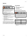
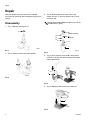
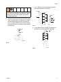
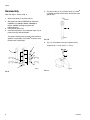
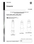
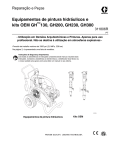
Instructions
Displacement Pump
311845C
- For portable spray application of architectural paints and coatings -
Model 288466, 288467, 288468, 288819
3300 psi (22.8 MPa, 25 bar) Maximum Working Pressure
Important Safety Instructions
Read all warnings and instructions in this manual.
Save these instructions.
Model 288466
Model 288467/288468
Model 288819
Ti8844a
Graco Inc. P.O. Box 1441 Minneapolis, MN 55440-1441
Copyright 2007, Graco Inc. is registered to I.S. EN ISO 9001
Warnings
Warnings
The following warnings are for the setup, use, grounding, maintenance, and repair of this equipment. The exclamation point symbol alerts you to a general warning and the hazard symbol refers to procedure-specific risk. Refer back
to these warnings. Additional, product-specific warnings may be found throughout the body of this manual where
applicable.
WARNING
EQUIPMENT MISUSE HAZARD
Misuse can cause death or serious injury.
• Do not operate the unit when fatigued or under the influence of drugs or alcohol.
• Do not exceed the maximum working pressure or temperature rating of the lowest rated system
component. See Technical Data in all equipment manuals.
• Use fluids and solvents that are compatible with equipment wetted parts. See Technical Data in all
equipment manuals. Read fluid and solvent manufacturer’s warnings. For complete information
about your material, request MSDS forms from distributor or retailer.
• Check equipment daily. Repair or replace worn or damaged parts immediately with genuine manufacturer’s replacement parts only.
• Do not alter or modify equipment.
• Use equipment only for its intended purpose. Call your distributor for information.
• Route hoses and cables away from traffic areas, sharp edges, moving parts, and hot surfaces.
• Do not kink or over bend hoses or use hoses to pull equipment.
• Keep children and animals away from work area.
• Comply with all applicable safety regulations.
MOVING PARTS HAZARD
Moving parts can pinch or amputate fingers and other body parts.
• Keep clear of moving parts.
• Do not operate equipment with protective guards or covers removed.
• Pressurized equipment can start without warning. Before checking, moving, or servicing equipment,
follow the Pressure Relief Procedure in this manual. Disconnect power or air supply.
2
311845C
Service
Service
Pressure Relief Procedure
The system pressure must be manually relieved to prevent the system from starting or spraying accidentally.
To reduce the risk of an injury from accidental spray
from the gun, splashing fluid, or moving parts, follow
the Pressure Relief Procedure whenever you,
•
•
•
•
Tools Needed
•
•
•
•
•
•
Vise
12-inch adjustable, open-end wrench (2)
Hammer, 20 oz. maximum
Small screwdriver
Throat Seal Liquid
Pick or long small screwdriver
Cleaning and Inspecting Parts
are instructed to relieve the pressure
stop spraying
check or service any of the system equipment
install or clean the spray nozzle.
1. Engage trigger lock.
2. Turn engine ON/OFF switch to OFF.
3. Move pump switch to OFF and turn pressure control
knob fully clockwise.
4. Unlock trigger lock. Hold metal part of gun firmly to
side of grounded metal pail and trigger gun to
relieve pressure.
5. Engage the trigger lock.
6. Open all fluid drain valves in the system, having a
waste container ready to catch drainage. Leave
drain valve(s) open until you are ready to spray
again.
If you suspect the spray tip or hose is clogged or that
pressure has not been fully relieved after following the
steps above, VERY SLOWLY loosen tip guard retaining
nut or hose end coupling to relieve pressure gradually,
then loosen completely. Clear hose or tip obstruction.
Never use a sharp or pointed tool to remove sleeve
or other components which could result in pump rupture and cause serious bodily injury. If the sleeve
cannot be removed easily, return the sleeve and cylinder to an authorized Graco distributor for removal.
•
•
311845C
Clean and inspect all parts. Replace worn or damaged parts.
Component
What to look for
Ball seats in intake valve
and piston
nicks or wear
Inside sleeve
worn or scratched
Piston rod
worn or scratched
Remove and clean the sleeve when you are repacking the pump.
3
Repair
Repair
See your sprayer instruction manual for complete
instructions for removing and installing the pump in your
sprayer.
3. (Fig. 3) Disassemble intake valve. Clean and
inspect o-ring (17). You may need to use a pick to
remove o-ring.
Spring (26) for model 288819 is optional and is not
included with the pump.
Disassembly
1. (Fig. 1) Remove packing nut (3).
3
26
(288467/288468)
18
26
(288819)
19
16
17
1
ti8845a
FIG. 1
ti8847b
2. (Fig. 2) Unscrew intake valve from cylinder.
FIG. 3
4. (Fig. 4) Use a hammer to tap piston rod (5) out of
cylinder (2), or flip pump over and tap piston rod out
against work bench.
5
2
ti8846a
FIG. 2
ti8848a
FIG. 4
5. (Fig. 5) Remove piston rod (5) from sleeve (4).
4
5
ti8849a
FIG. 5
4
311845C
Repair
7. (Fig. 7) Remove packing and glands from piston
rod. Note orientation for installation.
11
Do not clean or wipe piston valve (6) threads. Cleaning the piston valve threads could destroy the special
sealing patch and cause the piston valve to come
loose during operation.
6
5
6. (Fig. 6) Unscrew piston valve (6) from piston rod (5).
Clean and inspect parts. The piston has a special
thread locking/sealing patch. Do not remove the
patch. The patch allows for disassembly/assembly
procedures before it is necessary to apply Loctite®
to the threads.
13
12
10
9
8
ti8851a
FIG. 7
8. (Fig. 8) Remove throat packings and glands from
cylinder. Discard throat packings and glands.
6
23
5
22
21
ti8850a
FIG. 6
ti8853a
FIG. 8
311845C
5
Repair
Reassembly
5. (Fig 10) Install ball (11) in piston rod (5). If Loctite®
is applied to piston valve threads, ensure that none
gets on ball.
Note: For steps 1-4 refer to Fig. 9.
1. Stack male gland (7) on piston rod (5).
11
2. Alternately stack blue UHMWPE (8) and brown
UHMWPH (9) (288466, 288467, 2884680) or
leather (288819) packings on piston rod.
Note orientation.
3. Install female gland (10).
4. Install backup washer (13) and piston wiper (12) on
piston valve (6). Note orientation.
The special sealing patch on piston valve threads is
good for 4 repackings. Use Loctite® on piston valve
threads after 4 repackings.
5
ti8855a
FIG. 10
6. (Fig. 11) Install piston valve (6) to piston rod (5).
Torque to 55 +/- 3 ft-lb (74.57 +/- 4 N• m).
6
5
6
13
12
5
9
8
7
FIG. 9
6
10
ti8854a
ti8856a
FIG. 11
311845C
Repair
7. Soak all leather packings in SAE 30W oil for 1 hour
minimum prior to assembly.
Note: For steps 8-10 refer to Fig. 12.
8. Place male gland (20) in cylinder.
9. Alternately stack UHMWPE (21) and leather packings (22). Note orientation.
10. Place female gland (23) in top of cylinder. Seat
packings.
12. (Fig. 14) Install o-rings (14) inside cylinder (2) and
on sleeve (4). Slide sleeve (4) into bottom of cylinder
(2). Replace o-ring (15) if desired.
Place inside cylinder (2)
and push to shoulder
with sleeve (4).
2
23
22
21
4
14
OR
20
288467/
288468
288819
15
288466
ti8859a
FIG. 14
Note: O-ring (15) is not required for safe pump operation.
ti8857a
FIG. 12
11. (Fig. 13) Install packing nut (3) into cylinder and
hand tighten.
13. (Fig. 15) Grease top inch or two of piston rod (5)
that goes through the sleeve/cylinder assembly
throat packings. Grease piston packings at bottom
of piston pump.
Carefully slide piston assembly (5) into bottom of
sleeve/cylinder assembly (2) until pump rod protrudes out the top and piston packings are totally
inside the sleeve (4).
3
2
15
ti8858a
FIG. 13
4
CAUTION
Never slide piston assembly (5) into top of sleeve (4)
as this may damage piston packings.
5
ti8860a
ti8860a
FIG. 15
311845C
7
Repair
14. (Fig. 16) Reassembly intake valve with new o-ring
(17), seat (16) and ball (19). Seat may be flipped
over and used on the other side. Clean seat thoroughly.
Spring (26) for model 288819 is optional and is not
included with the pump.
18
19
16. Torque packing nut to:
140 +/- 10 in-lb (15 +/- 1 N•m) 288467/288468, 288819.
125 +/- 10 in-lb (14 +/- 1 N•m) 288466
When pump packings begin to leak, tighten packing
nut down until leakage stops or lessens. This allows
approximately 100 gallons of additional operation
before repacking is required.
26
(288467/ 288468)
26
(288819)
16
17
ti8847b
FIG. 16
15. (Fig. 17) Install intake valve on cylinder. Torque to:
200 +/- 5 ft-lb (271 +/- 7 N•m) 288467/288468, 288819.
110+/- 5 ft-lb (149 +/- 7 N•m) 288466.
FIG. 17
8
311845C
Parts
Parts
Model 288467/288468
Ref
1
2
11
3
4
12
13
5
6
24
6
7*
8*
9*
10*
11*
12*
13*
14*
15*
16†
17†*
18
19†*
20*
21*
23*
24*
25*
26*
3
25
23
2
8
21
15
14
20
4
5
14
26
18
7
9
Part
15E655
288482
288483
15J792
249121
287817
288469
288470
249177
189585
189588
107203
119636
15J800
108822
107306
240918
107098
198505
107167
15G658
15G657
112590
108832
245256
Description
Qty
HOUSING
1
CYLINDER (model 288467)
1
CYLINDER (model 288468)
NUT, packing
1
SLEEVE, cylinder (model 288467)
1
SLEEVE, cylinder (model 288468)
ROD, piston (model 288467)
1
ROD, piston (model 288468)
VALVE, piston
1
GLAND, packing, male
1
PACKING,VEE (blue)
8
PACKING,VEE (brown)
3
GLAND, packing, female
1
BALL, valve, check
1
WIPER, piston
1
WASHER, back up
1
PACKING, o-ring
2
PACKING, o-ring
1
SEAT, carbide
1
PACKING, o-ring
1
GUIDE, ball
1
BALL,SST
1
GLAND, male
1
PACKING,VEE (leather)
3
GLAND, female
1
PLUG, throat, seal
1
PACKING, o-ring
1
SPRING, intake ball
1
* Included in Repair Kit 287813
† Included in Repair Kit 240918
19
16
17
8
1
10
ti8826a
311845C
9
Parts
Model 288466
24
3
5
25
10
7
8
22
8
9
7
10
12
13
5
11
6
Ref
1
2
3
4
5
6
7*
8*
9*
10*
11*
12*
13*
14*
15*
16†
17†
18
19†*
22*
24*
25*
Part
195894
288727
193032
248210
288479
240150
183178
183185
101947
118504
15C998
107098
106556
244199
108526
193027
102972
183171
120818
Description
HOUSING, intake
CYLINDER
NUT, packing
SLEEVE, cylinder
ROD, piston
VALVE, piston
GLAND, packing, male
PACKING (blue)
PACKING,VEE (brown)
GLAND, packing, female
BALL, bearing
WIPER, piston
WASHER, backup
PACKING, o-ring
PACKING, o-ring
SEAT, carbide
PACKING, o-ring
GUIDE, ball
BALL
PACKING,VEE (leather)
PLUG
PACKING, o-ring
Qty
1
1
1
1
1
1
2
8
3
2
1
1
1
2
1
1
1
1
1
3
1
1
*Included in Repair Kit 288471
†Included in Repair Kit 244199
2
18
19
15
16
17
14
4
14
10
1
ti8825a
311845C
Parts
Model 288819
24
12
13
11
3
6
Ref
1
2
3
4
5
6
7*
8*
9*
10*
11*
12*
13*
14*
15*
16†
17†*
18
19†*
20*
23
24*
25*
26†
25
23
2
9
8
20
15
14
4
5
Part
15A303
288822
15J792
248979
288821
249177
189585
189588
118601
119636
15F183
108822
107306
245885
107098
15D158
118602
198768
194175
112590
108832
118600
Description
HOUSING, intake
CYLINDER, pump
NUT, packing
SLEEVE, cylinder
ROD, piston
VALVE, piston
GLAND, packing, male
PACKING, vee, blue
PACKING, vee, leather
GLAND, packing, female
BALL, ceramic, 0.5625 dia
WIPER, piston
WASHER, backup
PACKING, o-ring
PACKING, o-ring
SEAT, carbide
PACKING, o-ring
GUIDE, ball
BALL, ceramic, 0.875 dia
GLAND, packing, male
GLAND, female
PLUG, throat seal
PACKING, o-ring
SPRING, compression; optional,
not included with pump
Qty
1
1
1
1
1
1
1
8
6
1
1
1
1
2
1
1
1
1
1
1
1
1
1
1
14
* Included in Repair Kit 288820
† Included in Repair Kit 245885
18
26
19
16
9
7
17
8
1
10
311845C
ti9569a
11
Parts
Notes
12
311845C
Technical Data
Technical Data
Maximum working pressure
Fluid inlet size
Fluid outlet size
Wetted parts
311845C
3300 psi, 25 bar, 22.8 MPa
1-5/16 UN (m) models 288467/288468
3/4-14 npt (m) model 288466
3/8 npt (f)
stainless steel, PTFE, leather, nylon, zinc-plated carbon
steel, tungsten carbide, brass, fluorelastomer, acetal,
polyethylene, ceramic
13
Graco Standard Warranty
Graco Standard Warranty
Graco warrants all equipment referenced in this document which is manufactured by Graco and bearing its name to be free from defects in
material and workmanship on the date of sale to the original purchaser for use. With the exception of any special, extended, or limited warranty
published by Graco, Graco will, for a period of twelve months from the date of sale, repair or replace any part of the equipment determined by
Graco to be defective. This warranty applies only when the equipment is installed, operated and maintained in accordance with Graco’s written
recommendations.
This warranty does not cover, and Graco shall not be liable for general wear and tear, or any malfunction, damage or wear caused by faulty
installation, misapplication, abrasion, corrosion, inadequate or improper maintenance, negligence, accident, tampering, or substitution of
non-Graco component parts. Nor shall Graco be liable for malfunction, damage or wear caused by the incompatibility of Graco equipment with
structures, accessories, equipment or materials not supplied by Graco, or the improper design, manufacture, installation, operation or
maintenance of structures, accessories, equipment or materials not supplied by Graco.
This warranty is conditioned upon the prepaid return of the equipment claimed to be defective to an authorized Graco distributor for verification of
the claimed defect. If the claimed defect is verified, Graco will repair or replace free of charge any defective parts. The equipment will be returned
to the original purchaser transportation prepaid. If inspection of the equipment does not disclose any defect in material or workmanship, repairs will
be made at a reasonable charge, which charges may include the costs of parts, labor, and transportation.
THIS WARRANTY IS EXCLUSIVE, AND IS IN LIEU OF ANY OTHER WARRANTIES, EXPRESS OR IMPLIED, INCLUDING BUT NOT LIMITED
TO WARRANTY OF MERCHANTABILITY OR WARRANTY OF FITNESS FOR A PARTICULAR PURPOSE.
Graco’s sole obligation and buyer’s sole remedy for any breach of warranty shall be as set forth above. The buyer agrees that no other remedy
(including, but not limited to, incidental or consequential damages for lost profits, lost sales, injury to person or property, or any other incidental or
consequential loss) shall be available. Any action for breach of warranty must be brought within two (2) years of the date of sale.
GRACO MAKES NO WARRANTY, AND DISCLAIMS ALL IMPLIED WARRANTIES OF MERCHANTABILITY AND FITNESS FOR A
PARTICULAR PURPOSE, IN CONNECTION WITH ACCESSORIES, EQUIPMENT, MATERIALS OR COMPONENTS SOLD BUT NOT
MANUFACTURED BY GRACO. These items sold, but not manufactured by Graco (such as electric motors, switches, hose, etc.), are subject to
the warranty, if any, of their manufacturer. Graco will provide purchaser with reasonable assistance in making any claim for breach of these
warranties.
In no event will Graco be liable for indirect, incidental, special or consequential damages resulting from Graco supplying equipment hereunder, or
the furnishing, performance, or use of any products or other goods sold hereto, whether due to a breach of contract, breach of warranty, the
negligence of Graco, or otherwise.
FOR GRACO CANADA CUSTOMERS
The Parties acknowledge that they have required that the present document, as well as all documents, notices and legal proceedings entered into,
given or instituted pursuant hereto or relating directly or indirectly hereto, be drawn up in English. Les parties reconnaissent avoir convenu que la
rédaction du présente document sera en Anglais, ainsi que tous documents, avis et procédures judiciaires exécutés, donnés ou intentés, à la suite
de ou en rapport, directement ou indirectement, avec les procédures concernées.
Graco Information
TO PLACE AN ORDER, contact your Graco distributor or call 1-800-690-2894 to identify the nearest distributor.
All written and visual data contained in this document reflects the latest product information available at the time of publication.
Graco reserves the right to make changes at any time without notice.
This manual contains English. MM311845
Graco Headquarters: Minneapolis
International Offices: Belgium, China, Japan, Korea
GRACO INC. P.O. BOX 1441 MINNEAPOLIS, MN 55440-1441
www.graco.com
4/2007
14
311845C