1
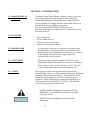
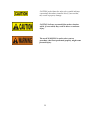
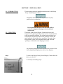
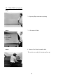
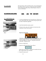
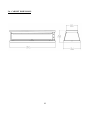
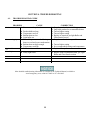
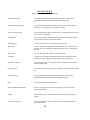
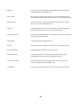
Henny Penny
Display Counter Warmer
Model DCW-2
OPERATOR’S MANUAL
LIMITED WARRANTY FOR HENNY PENNY EQUIPMENT
Subject to the following conditions, Henny Penny Corporation makes the following limited warranties to the original
purchaser only for Henny Penny appliances and replacement parts:
NEW EQUIPMENT: Any part of a new appliance, except baskets, lamps, and fuses, which proves to be defective
in material or workmanship within two (2) years from date of original installation, will be repaired or replaced
without charge F.O.B. factory, Eaton, Ohio, or F.O.B. authorized distributor. Baskets will be repaired or replaced
for ninety (90) days from date of original installation. Lamps and fuses are not covered under this Limited
Warranty. To validate this warranty, the registration card for the appliance must be mailed to Henny Penny within
ten (10) days after installation.
FILTER SYSTEM: Failure of any parts within a fryer filter system caused by the use of the non-OEM filters or
other unapproved filters is not covered under this Limited Warranty.
REPLACEMENT PARTS: Any appliance replacement part, except lamps and fuses, which proves to be defective
in material or workmanship within ninety (90) days from date of original installation will be repaired or replaced
without charge F.O.B. factory, Eaton, Ohio, or F.O.B. authorized distributor.
The warranty for new equipment covers the repair or replacement of the defective part and includes labor charges and
maximum mileage charges of 200 miles round trip for a period of one (1) year from the date of original installation.
The warranty for replacement parts covers only the repair or replacement of the defective part and does not include any
labor charges for the removal and installation of any parts, travel, or other expenses incidental to the repair or replacement of
a part.
EXTENDED FRYPOT WARRANTY:
Henny Penny will replace any frypot that fails due to manufacturing or
workmanship issues for a period of up to seven (7) years from date of manufacture. This warranty shall not cover any frypot
that fails due to any misuse or abuse, such as heating of the frypot without shortening.
0 TO 3 YEARS: During this time, any frypot that fails due to manufacturing or workmanship issues
will be replaced at no charge for parts, labor, or freight. Henny Penny will either install a new frypot at no
cost or provide a new or reconditioned replacement fryer at no cost.
3 TO 7 YEARS: During this time, any frypot that fails due to manufacturing or workmanship issues
will be replaced at no charge for the frypot only. Any freight charges and labor costs to install the new
frypot as well as the cost of any other parts replaced, such as insulation, thermal sensors, high limits,
fittings, and hardware, will be the responsibility of the owner.
Any claim must be presented to either Henny Penny or the distributor from whom the appliance was purchased. No
allowance will be granted for repairs made by anyone else without Henny Penny’s written consent. If damage occurs during
shipping, notify the sender at once so that a claim may be filed.
THE ABOVE LIMITED WARRANTY SETS FORTH THE SOLE REMEDY AGAINST HENNY PENNY FOR ANY
BREACH OF WARRANTY OR OTHER TERM. BUYER AGREES THAT NO OTHER REMEDY (INCLUDING
CLAIMS FOR ANY INCIDENTAL OR CONSEQUENTIAL DAMAGES) SHALL BE AVAILABLE.
The above limited warranty does not apply (a) to damage resulting from accident, alteration, misuse, or abuse; (b) if the
equipment’s serial number is removed or defaced; or (c) for lamps and fuses. THE ABOVE LIMITED WARRANTY IS
EXPRESSLY IN LIEU OF ALL OTHER WARRANTIES, EXPRESS OR IMPLIED, INCLUDING MERCHANTABILITY
AND FITNESS, AND ALL OTHER WARRANTIES ARE EXCLUDED. HENNY PENNY NEITHER ASSUMES NOR
AUTHORIZES ANY PERSON TO ASSUME FOR IT ANY OTHER OBLIGATION OR LIABILITY.
Revised 01/01/07
FM05-052-A
8-15-08
TABLE OF CONTENTS
Section
Page
Section 1. INTRODUCTION........................................................................................................ 1
1-1. Heated Display Cabinet ...................................................................................... 1
1-2. Features............................................................................................................... 1
1-3. Proper Care ......................................................................................................... 1
1-4. Assistance ........................................................................................................... 1
1-5. Safety .................................................................................................................. 2
Section 2. INSTALLATION.........................................................................................................
2-1. Introduction ........................................................................................................
2-2. Unpacking...........................................................................................................
2-3. Location ..............................................................................................................
2-4. Electric Data Table .............................................................................................
2-5. Light Bulbs and Glass Panels .............................................................................
2-6. Cabinet Dimensions............................................................................................
3
3
3
5
5
5
6
Section 3. OPERATION ............................................................................................................... 7
3-1. Introduction ........................................................................................................ 7
3-2. Operating Controls ............................................................................................. 7
3-3. Start-Up.............................................................................................................. 10
3-4. Operation with Product ...................................................................................... 10
3-5. Shut-Down and Cleanup .................................................................................... 10
Section 4. TROUBLESHOOTING............................................................................................... 12
4-1. Troubleshooting Guide ...................................................................................... 12
GLOSSARY............................................................................................................................ 13
SECTION 1. INTRODUCTION
1-1. HEATED DISPLAY
CABINET
The Henny Penny Heated Display Cabinet is a basic unit of food
processing equipment used to display the food product and
maintain the temperature of hot foods in the commercial food
service operation. This highly efficient, quality-built cabinet will
keep hot foods at proper holding temperatures
The Henny Penny Heated Display Cabinets have seethru doors which allow viewing and access to the hot foods from
both front and back.
1-2. FEATURES
•
•
•
•
Easy to keep clean
DCW-2 holds two trays
All heat sources are adjustable
Flip-up, see-through door panels
1-3. PROPER CARE
As in any unit of food service equipment, the Henny Penny
Heated Display Cabinet does require care and maintenance.
Requirements for the maintenance and cleaning are contained
in this manual and must become a regular part of the
operation of the unit at all times.
1-4. ASSISTANCE
Should you require outside assistance, just call your local
independent Henny Penny distributor in your area, call Henny
Penny Corp. at 1-800-417-8405 toll free or 1-937-456-8405,
or go to Henny Penny online at www.hennypenny.com.
1-5. SAFETY
The only way to ensure safe operation of the Henny Penny
Heated Display Cabinet is to fully understand the proper installation,
operation, and maintenance procedures. The instructions in this
manual have been prepared to aid you in learning the proper
procedures. Where information is of particular importance or is
safety related, the words NOTICE, CAUTION, or WARNING
are used. Their usage is described below.
SAFETY ALERT SYMBOL is used with DANGER,
WARNING, or CAUTION which indicates a personal
injury type hazard.
NOTICE is used to highlight especially important
information.
1
CAUTION used without the safety alert symbol indicates
a potentially hazardous situation which, if not avoided,
may result in property damage.
CAUTION indicates a potentially hazardous situation
which, if not avoided, may result in minor or moderate
injury.
The word WARNING is used to alert you to a
procedure, that if not performed properly, might cause
personal injury.
2
SECTION 2. INSTALLATION
2-1. INTRODUCTION
This section provides the installation instructions for the Henny
Penny Heated Display Cabinet.
Installation of this unit should be performed only by a
qualified service technician.
2-2. UNPACKING
Do not puncture the skin of the unit with drills or
screws as component damage or electrical shock
could result.
The Henny Penny Heated Display Cabinet has been tested,
inspected, and expertly packed to ensure arrival at its destination
in the best possible condition. The cabinet has been bolted to a
wooden skid. All glass items have been packed in cartons and
taped inside the unit and the doors taped shut. The unit is then
packed inside a triple wall corrugated carton with sufficient
padding to withstand normal shipping treatment.
Any shipping damages should be noted in the presence of the
delivery agent and signed prior to his or her departure.
Step 1
To remove the Henny Penny Heated Display Cabinet from the
carton, you should:
1. Carefully cut banding straps.
3
2-2. UNPACKING (Continued)
Step 2
2. Open top flaps and remove packing.
Step 3
Step 4
3. Lift carton off skid.
4. Remove four bolts from under skid.
The unit is now ready for location and set-up.
4
2-3. LOCATION
2-4. ELECTRIC DATA TABLE
2-5. LIGHT BULBS AND
GLASS PANELS
Place the unit on a table, preferably with a cut-out opening below
the cabinet to allow easy service connections and serviceability.
When setting up the Henny Penny Heated Display Cabinet, be
sure to level the table.
Model
Volts
Phase
DCW-2
120/230
1
Watts Amps
760
4.7
1. Cut the tape holding the doors shut and remove all boxes and
boxes and packing. One carton contains the glass panels and
the other contains the light bulbs.
2. Install the light bulbs and glass panels.
3. The unit is now ready to be cleaned per instructions in the
Operations section of this manual.
Step 1
Replacing Light Bulbs
Light bulbs and glass may be hot. Severe burns could result.
1. Remove the glass panel by carefully pushing up on back of
panel and sliding away from you. The panel will fall into
your hand. See photo at left.
2. Remove the light bulb.
3. Replace the light bulb Henny Penny offered.
Step 2
If this bulb is not available, a standard 60 watt bulb will work
until a long life bulb can be obtained.
4. Replace the glass panel.
5
2-6. CABINET DIMENSIONS
6
SECTION 3. OPERATING INSTRUCTIONS
3-1. INTRODUCTION
This section provides operating procedures for the heated display
cabinets. The Introduction, Installation and Operation sections
should be read, and all instructions should be followed before
operating the cabinet.
3-2. OPERATING CONTROLS
Figures 3-1 through 3-7 identify and describe the function of all
the operating controls and the major components of the cabinet.
1
2
3
4
Figure 3-1
Figure 3-2
Figure 3-3
Figure 3-4
7
3-2. OPERATING CONTROLS (Continued)
Figure 3-5
Figure 3-6
Figure 3-7
8
3-2. OPERATING CONTROLS (Continued)
Fig. No. Item No.
Description
Function
3-1
1
Radiant Heat
Infinite Regulator
A time proportioning controller, which means the higher
the number setting, the greater percentage of time the
Radiant heat will be on
3-1
2
Tubular Heat
Infinite Regulator
A time proportioning controller, which means the higher
the number setting, the greater percentage of time the
Tubular heat will be on
3-1
3
Light Fuse Holder
A 15 amp protective device for the lighting circuit, that
must be replaced by a fuse of the same size and rating
3-1
4
Power Switch
A two-position, three pole switch used to turn on and
off the heat control systems
3-2
5
Radiant Heater
A long tubular heater mounted in a reflector located in
the ceiling panel of the unit
3-3
8
Lower Level
Pan Grid
A grid that sets in the lower level to prevent a bun pan
from dropping into the bottom of the unit when being lifted
out
3-4
9
Pan Support Top
Tilts the bun pans used in the top toward the customer
side of the unit
3-5
10
Light Bulb
A 60 watt rated, long-life bulb that should be replaced
by the same wattage bulb
3-6
11
Lamp Socket
A high temperature ceramic socket for holding the light
bulb
3-7
12
Tinted Glass
Specially tempered colored glass with a thin film of
silicone that protects the light bulbs as well as color
the light
9
3-3. START-UP
Before using, the Henny Penny Heated Display Cabinet
should be thoroughly cleaned as indicated in the Shut-Down
and Cleanup section of this manual.
1. Move all switches and controls on the cabinet to the OFF
position.
2. Turn on power supply for the cabinet at the main circuit
breaker.
Step 2
3. Place the grids in the lower level.
4. Install the perforated bun pans well.
5. Close the doors.
6. Turn the power switch to the ON position.
7. Turn the light switch to the ON position.
Step 3
8. Turn the radiant heat switch to the desired setting. We
recommend starting at “6” for the lower radiant. If you have
upper radiant, start at “4”. These settings are adjustable and
may change as you become familiar with the food product
in this unit.
3-4. OPERATION WITH
OPERATION WITH PRODUCT
1. Place product on wire grids in the pans.
2. Serve product from the outside edges first. The product
closest to the door opened often will cool fastest.
3. Only leave the doors open when demand requires. During
slow periods, keep the doors closed.
10
3-5. SHUT-DOWN AND
CLEANUP
1. Turn the radiant heat to OFF
2. Open the doors.
3. Remove all the pans.
4. Remove the grids from the lower level and clean with
soap and water at sink.
Do not use steel wool, other abrasive cleaners or
cleaners/sanitizers containing chlorine, bromine, iodine
or ammonia chemicals, as these will deteriorate the
stainless steel material and shorten the life of the unit.
5. Clean all surfaces with a soft cloth, soap, and water.
6. Clean around electrical controls with a damp cloth.
7. Turn off the lights and power switch.
8. Leave the doors open until ready to use again.
11
SECTION 4. TROUBLESHOOTING
4-1.
TROUBLESHOOTING GUIDE
PROBLEM
CAUSE
z Doors are not kept closed
CORRECTION
Keep doors closed when holding possible
Only hold product for recommended times
Turn to higher setting
Turn to higher setting
Replace as required, per light Bulbs and
Glass Panels section
z Keep doors closed when possible
z
z
z
z
z
Product not holding
Doors are fogging
z
z
z
z
z
Lights will not turn
on
Not all lights on
z Faulty light bulbs
Product held too long
Temperature too low
Radiant heat too low
Light bulbs out
Doors left open too much allowing
doors to cool and cause condensation
z Radiant heat not high enough
z Turn to higher setting
z Temperature too high
z See recommended settings and temperature
z Defective fuse
z Replace 15 amp fuse
z Replace with recommended bulb, per Light
Bulbs and Glass Panels section
More detailed troubleshooting information is available in the Technical Manual, available at
www.hennypenny.com, or 800-417-8405 or 937-456-8405.
12
GLOSSARY
HENNY PENNY HOLDING CABINETS
air temperature probe
a round device located inside the cabinet that measures the inside air
temperature and sends that information to the control panel
concentration ring assembly
a metal assembly located in the water pan in the bottom of the unit that
helps keep an even humidity level inside the cabinet
clean water pan setpoint
a preset temperature at which a sensor warns the operator that the water pan
has excessive lime deposits
control panel
the components that control the operating systems of the unit; the panel is
located on the top front surface of the cabinet
deliming agent
a cleaner used to remove lime deposits in the water pan
drain valve
a device that lets the water drain from the water pan into a shallow pan on
the floor; the valve should be closed while the unit is in use if humidity is
desired
float switch
a device that senses low water levels in the water pan
food probe
a sensor located outside the cabinet that, when inserted into the product,
communicates the temperature of the product to the control panel
food probe receptacle
the connection where the food probe is inserted in order to communicate
with the control panel
humidity sensor
a device that measures the percentage of humidity inside the cabinet during
use
humidity setting
a preset moisture level at which the cabinet operates; this setting is
programmed at the factory but can be changed in the field
LED
an electronic light on the control panel
minimum holding temperature
the lowest temperature at which a food product can be safely held for
human consumption
module
the removable top part of the cabinet that contains all of the operating
system
out of water trip point
a preset temperature at which a sensor warns the operator that the water
pan needs refilled
13
parameters
a preset group of setpoints designed for holding specific food products at
certain temperature and humidity levels
power switch
the ON/OFF switch that sends electricity to the unit’s operating systems;
this switch does not disconnect the electrical power from the wall to the unit
pressure sprayer
a device that shoots a stream of water under pressure; this device should
NOT be used to clean a holding cabinet
probe clip
a metal holder that attaches to the outside of the control panel to hold the
food probe when not in use; the clip is an optional accessory
product load capacity
the highest recommended number of pounds/kilograms of food product that
can be safely held in the cabinet
proof function
a program used for allowing bread to rise
set point
a preset temperature or humidity; the setpoint is a programmable feature
system initialization
a programming process that resets factory settings
temperature setting
a preset temperature up to which the cabinet will heat; this setting is
programmed at the factory but can be changed in the field
vent activation switch
an automatic control that opens and closes the vent on the rear of the
cabinet to maintain the preset humidity level
vented panels
openings on the cabinet that allow air access on the sides and rear of the
14