1
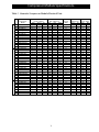
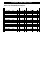
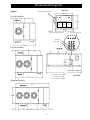
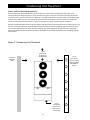
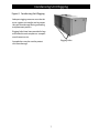
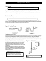
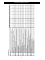
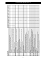
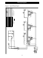
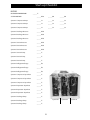
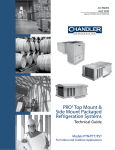
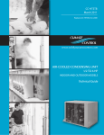
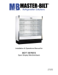
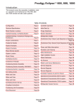
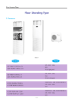
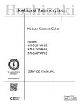
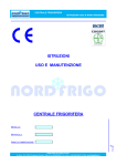
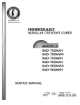
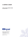
Multiple Compressor Condensing Units H-IM-FP April 2011 Part No. 25006801 Updates to March 2004 version. Installation and Operation Manual Table of Contents Nomenclature................................................................................2 General Safety Information......................................................2 Compressor Module Specifications...................................3-4 Dimensional Diagrams...............................................................5 Condensing Unit Placement....................................................6 Condensing Unit Rigging..........................................................7 Refrigeration Piping and Line sizing...............................8-10 Leak Detection and Evacuation........................................... 11 Field Wiring.................................................................................. 12 Refrigeration Charging............................................................ 13 Operational Checkout............................................................. 14 System Balancing...................................................................... 14 Preventive Maintenance...................................................15-17 Parts................................................................................................ 18 Wiring Diagram.......................................................................... 19 Start-up Checklist................................................................20-21 Nomenclature TPC1 - One Condenser Fan Cabinet TPC2 - Two Condenser Fan Cabinet TPC3 - Three Condenser Fan Cabinet General Safety Information 1. Installation and maintenance to be performed only by certified personnel who are familiar with this type of equipment. 2. Make sure that all field wiring conforms to the requirements of the equipment and all applicable national and local codes. 3. Avoid contact with sharp edges and coil surfaces. They are a potential injury hazard. 4. Make sure all power sources are disconnected before any service work is done on units. Inspection Responsibility should be assigned to a dependable individual at the job site to receive material. Each shipment should be carefully checked against the bill of lading. The shipping receipt should not be signed until all items listed on the bill of lading have been accounted for. Check carefully for concealed damage. Any shortage or damages should be reported to the delivering carrier. Damaged material becomes the delivering carrier’s responsibility and should not be returned to the manufacturer unless prior approval is given to do so. When uncrating, care should be taken to prevent damage. Heavy equipment should be left on its shipping base until it has been moved to the final location. © 2011, Heatcraft Refrigeration Products LLC 2 Compressor Module Specifications Low Temp. Medium Temp. High Temp. Table 1. Hermetic Compressor Module Electrical Data HP 1/2 1 1/2 1 1/2 2 2 3 3 4 4 5 5 3/4 1 1 1/2 1 1/2 2 2 2 1/2 2 1/2 3 3 3 1/4 3 1/4 4 4 5 5 1/2 3/4 1 1 1 1 1 1/2 1 1/2 2 1/2 2 1/2 3 3 Hermetic Compressor Model ART82C1-CAV CR18KQ-PFV CR18KQ-TF5 CR24KQ-PFV CR24KQ-TF5 CR37KQ-PFV CR37KQ-TF5 CR53KQ-PFV CR53KQ-TF5 CRN-0500-PFV CRN-0500-TF5 RS64C2-CAV RS70C1-PFV CS10K6E-PFV CS10K6E-TF5 CS12K6E-PFV CS12K6E-TF5 CS14K6E-PFV CS14K6E-TF5 CS18K6E-PFV CS18K6E-TF5 CS20K6E-PFV CS20K6E-TF5 CS27K6E-PFV CS27K6E-TF5 CS33K6E-PFV CS33K6E-TF5 RST45C1E-CAV RST55C1E-CAV RST64C1E-CAV RS70C1E-PFV CF04K6E-PFV CF04K6E-TF5 CF06K6E-PFV CF06K6E-TF5 CF09K6E-PFV CF09K6E-TF5 CF12K6E-PFV CF12K6E-TF5 Compressor Electrical Rating Volts Phase Hz 208-230 1 60 208-230 1 50/60 208-230 3 50/60 208-230 1 50/60 208-230 3 50/60 208-230 1 50/60 208-230 3 50/60 208-230 1 50/60 208-230 3 50/60 208-230 1 60 208-230 3 60 208-230 1 50/60 208-230 1 60 208-230 1 60 208-230 3 60 208-230 1 60 208-230 3 60 208-230 1 60 208-230 3 60 208-230 1 60 208-230 3 60 208-230 1 60 208-230 3 60 208-230 1 50/60 208-230 3 50/60 208-230 1 50/60 208-230 3 50/60 208-230 1 50/60 208-230 1 50/60 208-230 1 50/60 208-230 1 60 208-230 1 60 208-230 3 60 208-230 1 60 208-230 3 60 208-230 1 60 208-230 3 60 208-230 1 60 208-230 3 60 Compressor Data Crankcase RLA = MCC/1.56 Heater Refrigerant RLA LRA MCC Watts Type Lbs. 5.9 30.0 5.9 48 22 10 8.1 41.0 12.6 40 22 10 4.9 40.0 7.7 40 22 10 12.2 70.5 19.0 40 22 10 5.1 55.0 8.0 40 22 10 16.7 100.3 26.0 40 22 25 9.9 85.0 15.5 40 22 25 26.0 140.0 40.5 40 22 25 16.3 107.0 25.5 40 22 25 30.8 142.0 48.0 40 22 25 19.2 130.0 30.0 40 22 25 6.9 37.0 10.8 42 22 10 6.3 34.2 9.8 42 22 10 9.8 56.0 15.3 40 404a 9 6.7 51.0 10.5 40 404a 9 9.8 56.0 15.3 40 404a 9 6.7 51.0 10.5 40 404a 9 11.2 61.0 17.4 40 404a 9 8.2 55.0 12.8 40 404a 9 14.4 82.0 22.4 40 404a 22 9.4 65.5 14.6 40 404a 22 16.7 96.0 26.0 40 404a 22 10.3 75.0 16.0 40 404a 22 21.5 121.0 33.5 40 404a 22 13.7 105.0 21.4 40 404a 22 27.6 125.0 43.0 40 404a 22 16.8 102.0 26.2 40 404a 22 4.6 26.5 7.1 35 404a 9 6.1 33.7 9.5 35 404a 9 8.0 43.0 12.5 35 404a 9 6.3 34.2 9.8 45 404a 9 8.6 59.2 13.4 50 404a 9 5.7 52.0 8.9 50 404a 9 10.3 59.2 16.0 50 404a 9 6.3 52.0 9.8 50 404a 9 15.0 87.0 23.4 50 404a 9 9.2 72.2 14.3 50 404a 9 18.4 105.0 28.7 50 404a 9 11.0 85.0 17.2 50 404a 9 3 Evap. Temp. Min. Max 0 40 0 40 0 40 0 40 0 40 0 40 0 40 0 40 0 40 0 40 0 40 0 30 0 40 -25 30 -25 30 -25 30 -25 30 -25 30 -25 30 -25 30 -25 30 -25 30 -25 30 -25 30 -25 30 -25 30 -25 30 -25 30 -25 30 -25 30 -25 30 -40 0 -40 0 -40 0 -40 0 -40 0 -40 0 -40 0 -40 0 Compressor Module Specifications Low Temp. Medium Temp. Table 2. Scroll Compressor Module Electrical Data HP 2 2 2 1/2 2 1/2 3 3 3 1/2 3 1/2 4 1/2 4 1/2 5 1/2 5 1/2 6 2 2 2 1/2 2 1/2 3 3 3 1/2 3 1/2 4 1/2 4 1/2 5 1/2 5 1/2 6 Scroll Compressor Model ZS15K4E-PFV ZS15K4E-TF5 ZS19K4E-PFV ZS19K4E-TF5 ZS21K4E-PFV ZS21K4E-TF5 ZS26K4E-PFV ZS26K4E-TF5 ZS30K4E-PFV ZS30K4E-TF5 ZS38K4E-PFV ZS38K4E-TF5 ZS45K4E-TF5 ZF06K4E-PFV ZF06K4E-TF5 ZF08K4E-PFV ZF08K4E-TF5 ZF09K4E-PFV ZF09K4E-TF5 ZF11K4E-PFV ZF11K4E-TF5 ZF13K4E-PFV ZF13K4E-TF5 ZF15K4E-PFV ZF15K4E-TF5 ZF18K4E-TF5 Compressor Electrical Rating Volts Phase Hz 208-230 1 60 208-230 3 60 208-230 1 60 208-230 3 60 208-230 1 60 208-230 3 60 208-230 1 60 208-230 3 60 208-230 1 60 208-230 3 60 208-230 1 60 208-230 3 60 208-230 3 60 208-230 1 60 208-230 3 60 208-230 1 60 208-230 3 60 208-230 1 60 208-230 3 60 208-230 1 60 208-230 3 60 208-230 1 60 208-230 3 60 208-230 1 60 208-230 3 60 208-230 3 60 Compressor Data Crankcase RLA = MCC/1.56 Heater Refrigerant RLA LRA MCC Watts Type Lbs. 12.2 61.0 19.0 40 404a 22 8.3 55.0 13.0 40 404a 22 14.7 73.0 23.0 40 404a 22 8.7 63.0 13.6 40 404a 22 14.7 88.0 23.0 80 404a 22 9.9 77.0 15.5 80 404a 22 18.6 109.0 29.0 80 404a 22 12.2 88.0 19.0 80 404a 22 24.0 129.0 37.5 80 404a 22 13.5 99.0 21.0 80 404a 22 28.8 169.0 45.0 80 404a 22 19.2 123.0 30.0 80 404a 22 21.5 156.0 33.5 80 404a 22 12.2 61.0 19.0 40 404a 22 8.3 55.0 13.0 40 404A 22 14.7 73.0 23.0 40 404a 22 8.7 63.0 13.6 40 404a 22 12.8 88.0 20.0 80 404a 22 8.7 77.0 13.5 80 404a 22 16.0 109.0 25.0 80 404a 22 10.9 88.0 17.0 80 404a 22 22.4 129.0 35.0 80 404a 22 11.9 99.0 18.5 80 404a 22 25.0 169.0 39.0 80 404a 22 17.0 123.0 26.5 80 404a 22 19.6 156.0 30.5 80 404a 22 4 Evap. Temp. Min. Max -5 35 -5 35 -5 35 -5 35 -5 35 -5 35 -5 35 -5 35 -5 35 -5 35 -5 35 -5 35 -5 35 -40 0 -40 0 -40 0 -40 0 -40 0 -40 0 -40 0 -40 0 -40 0 -40 0 -40 0 -40 0 -40 0 Dimensional Diagrams Figure 1. End View Optional Disconnect Switch One Fan Top View System Position 3 2 1 Electrical Knockout (4) Please note system positions. Liquid Lines Suction Lines Two Fan Top View SYS .1 X = 100.50 (Three Fan Length) X = 78.00 (Two Fan Length) X = 59.00 (Single Fan Length) Three Fan Top View 5 SYS. 2 .3 SYS Side View Condensing Unit Placement Space and Location Requirements The most important consideration which must be taken into account when deciding upon the location of aircooled equipment is the provision for a supply of ambient air to the condenser, and removal of heated air from the condensing unit or remote condenser area. Where this essential requirement is not adhered to, it will result in higher head pressures, which cause poor operation and potential failure of equipment. Units must not be located in the vicinity of steam, hot air or fume exhausts. Corrosive atmospheres require custom designed condensers. Another consideration which must be taken is that the unit should be mounted away from noise sensitive spaces and must have adequate support to avoid vibration and noise transmission into the building. Units should be mounted over corridors, utility areas, rest rooms and other auxiliary areas where high levels of sound are not an important factor. Sound and structural consultants should be retained for recommendations. (Refer to actual building plans for unit locations.) Figure 2. Condensing Unit Placement 3 Feet from Building Wall 3 Feet (minimum) Clearance to the Next Unit 6 3 Feet (minimum) Clearance for Contractor to Service Unit. 3 Feet (minimum) Clearance from unit to an Open Block Wall or Shrubs. Condensing Unit Rigging Figure 3. Condensing Unit Rigging Adequate rigging measures must be taken to support unit weight and to protect the unit from damage during unloading and placement process. Rigging holes have been provided in legs and under the unit compressor compartment frame to assist. Rigging Holes Spreader bars may be used to protect unit from damage. 7 Refrigeration Piping And Line Sizing Refrigeration Piping And Line Sizing The system as supplied by Heatcraft Refrigeration Products, was thoroughly cleaned and dehydrated at the factory. Foreign matter may enter the system by way of the evaporator to condensing unit piping. Therefore, care must be used during installation of the piping to prevent entrance of foreign matter. Install all refrigeration system components in accordance with applicable local and national codes and in conformance with good practice required for the proper operation of the system. The refrigerant pipe size should be selected from the tables in Refrigeration System Installation Manual, Part Number 25001201. The interconnecting pipe size is not necessarily the same size as the stub-out on the condensing unit or the evaporator. The following procedures should be followed: (a) Do not leave dehydrated compressors or filter-driers on condensing units open to the atmosphere any longer than is absolutely necessary. (b) Use only refrigeration grade (ACR) copper tubing, properly sealed against contamination. (c) Suction lines should slope 1/4” per 10 feet towards the compressor (in direction of flow). (d) Suitable P-type oil traps should be located at the base of each suction riser to enhance oil return to the compressor. (e) For desired method of superheat measurement, a pressure tap should be installed in each evaporator suction line in the proximity of the expansion valve bulb. (f ) When brazing refrigerant lines, an inert gas should be passed through the line at low pressure to prevent scaling and oxidation inside the tubing. Dry nitrogen is preferred. (g) Use only a suitable silver solder alloy on suction and liquid lines. (h) Limit the soldering paste of flux to the minimum required to prevent contamination of the solder joint internally. Flux only the male portion of the connection, never the female. After brazing, remove excess flux. (i) Wrap expansion valves with wet rags during brazing to the liquid line. CAUTION: If the temperature gets too high, these components may be damaged. Heat absorbing compounds or wet rags must be used to protect the expansion valve when brazing to the refrigerant piping/line connections, and the suction line sensor must be removed per above instructions. (j) Do not use “bull head” tees. This will cause oil return problems and can cause poor performance. (k) If isolation valves are installed at the evaporator, full port ball valves should be used. 8 Refrigeration Piping Suction Lines NOTE: If the suction line must rise to the point higher than the suction connection on the evaporator, a suction line trap at the outlet of the evaporator must be provided. Horizontal suction lines should slope away from the evaporator toward the compressor at the rate of 1/4’ per 10 feet for good oil return. When multiple evaporators are connected in series using a common suction line, the branch suction lines must enter the top of the common suction line. Suction lines that are outside of refrigerated space must be insulated. See “Line Insulation” for more information. Suction Line Risers NOTE: To provide proper oil return, a suction trap must be provided at the base of all suction risers. Prefabricated wrought copper traps are available, or a trap can be made by using two street ells and one regular ell. The suction trap must be the same size as the suction line. For long vertical risers, additional traps may be necessary. Generally, one trap is recommended for each length of pipe (approximately 20 feet) to insure proper oil movement. See Figure 4 below for methods of constructing proper suction line P-traps. Figure 4. Suction P-traps Condensate Drain Lines Copper drain lines should be used and properly protected from freezing. In running drain lines, provide a minimum of 4 inches per foot pitch for proper drainage. Drain lines should be at least as large as the evaporator drain connection. All plumbing connections should be made in accordance with local plumbing codes. All condensate drain lines must be trapped, and run to an open drain. They must never be connected directly to the sewer systems. Traps in the drain line must be located in a warm ambient. We recommend a trap on all evaporators. Traps located outside, or extensive outside runs of drain line must be wrapped with a drain line heater. The heater should be Figure 5. Drain Line connected so that it is continuously on. It is recommended that the drain line be insulated to prevent heat loss. A heat input of 20 watts per lineal foot of drain line for 0ºF (-18°C) room applications and 30 watts per lineal foot for -20°F (-29°C) rooms is satisfactory. Inspect the drain pan periodically to insure free drainage of condensate. If the drain pan contains standing water, check for proper installation. The drain pan should be cleaned regularly with warm soapy water. WARNING: All power must be disconnected before cleaning. The drain pan also serves as cover for hazardous moving parts. Operation of unit without drain pan constitutes a hazard. NOTE: Always trap drain lines individually to prevent vapor migration. 9 Refrigeration Piping Figure 6. Example of Pipe Support 1. Normally, any straight run of tubing must be supported in at least two locations near each end of the run. Long runs require additional supports. The refrigerant lines should be supported and fastened properly. As a guide, 3/8 to 7/8 should be supported every 5 feet, 1-1/8 and 1-3/8 every 7 feet; and 1-5/8 and 2-1/8 every 9 to 10 feet. 2. When changing directions in a run of tubing, no corner should be left unsupported. Supports should be placed a maximum of 2 feet in each direction from the corner. 3. Piping attached to a vibrating object (such as a compressor or compressor base) must be supported in such a manner that will not restrict the movement of the vibrating object. Rigid mounting will fatigue the copper tubing. 4. Do not use short radius ells. Short radius elbows have points of excessive stress concentration and are subject to breakage at these points. 5. Thoroughly inspect all piping after the equipment is in operation and add supports wherever line vibration is significantly greater than most of the other piping. Extra supports are relatively inexpensive as compared to refrigerant loss. Figure 7. Line Insulation After the final leak test, refrigerant lines exposed to high or low ambient conditions should be insulated to reduce heat loss or gain and prevent the formation of flash gas in the liquid lines. Suction lines should be insulated with 3/4" wall Armstrong “Armaflex” or equivalent. Liquid lines should also be insulated with 1/2-inch wall insulation or better. The insulation located in outdoor environments should be protected from UV exposure to prevent deterioration of insulating value. 10 Leak Detection And Evacuation Leak Testing After all lines are connected, the entire system must be leak tested. The complete system should be pressurized to not more than 150 PSIG with refrigerant and dry nitrogen. The use of an electronic type of leak detector is highly recommended because of its greater sensitivity to small leaks. As a further check, it is recommended that this pressure be held for a minimum of 12 hours and then rechecked. For a satisfactory installation, the system must be leak tight. Leak detection can be carried out in the conventional manner. If HCFC or CFC tracer gas is used, care must be taken to completely remove all traces of the gas prior to introducing HFC’s. Electronic leak detectors are now available that will sense HFC’s. This is considered preferable since it removes the possibility of chlorine remaining in the system after leak testing with HCFC’s and/or HCFC’s. There is a view that even small quantities of chlorine may act as a catalyst encouraging copper plating and/or corrosion and should therefore be avoided. Within the last several years, manufacturers have developed fluorescent dye leak detection systems for use with refrigerants. These dyes mix with the lubricant and, when exposed to an ultraviolet light, fluoresce to indicate the location of leaks. Copeland has tested and approved the Rigid “System Safe” dye and found it to be compatible with the compressor materials in systems. Evacuation CAUTION: Do not use the refrigeration compressor to evacuate the system. Do not start the compressor while it is in a vacuum. Due to the smaller molecule size of HFC’s, they will tend to leak more readily than CFC. Consequently, it is of the utmost importance that proper system evacuation and leak detection procedures be employed. Copeland recommends a minimum evacuation to 500 microns. In addition, a vacuum decay test is strongly recommended to assure there is not a large pressure differential between the system and vacuum pump. Good evacuation processes include frequent vacuum pump oil changes and large diameter, short hose connections to both high and low sides of the system preferably using bronze braided hose. A good, deep vacuum pump should be connected to both the low and high side evacuation valves with copper tube or high vacuum hoses (1/4” ID minimum). If the compressor has service valves, they should remain closed. A deep vacuum gauge capable of registering pressure in microns should be attached to the system for pressure readings. A shut-off valve between the gauge connection and vacuum pump should be provided to allow the system pressure to be checked after evacuation. Do not turn off vacuum pump when connected to an evacuated system before closing shut-off valve. The vacuum pump should be operated until a pressure of 1,500 microns absolute pressure is reached – at which time the vacuum should be broken with the refrigerant to be used in the system through a drier until the system pressure rises above “0” psig. NOTE: Refrigerant used during evacuation can not be vented. Reclaim all used refrigerant. EPA regulations are constantly being updated. Ensure your procedures follow correct regulations. Repeat this operation a second time. Open the compressor’s service valves and evacuate the entire system to 500 microns absolute pressure. Raise the pressure to 2 psig with the refrigerant and remove the vacuum pump. 11 Field Wiring WARNING: All wiring must be done in accordance with applicable codes and local ordinances. The field wiring should enter the areas as provided on the unit. The wiring diagram for each unit is located on the inside of the electrical panel door. All field wiring should be done in a professional manner and in accordance with all governing codes. Before operating unit, double check all wiring connections, including the factory terminals. Factory connections can vibrate loose during shipment. 1. The nameplate on the unit is marked with the electrical characteristic for wiring the unit. 2. Consult the wiring diagram in the unit cooler and in the condensing unit for proper connections. 3. Wire type should be of copper conductor only and of the proper size to handle the connected load. 4. The unit must be grounded. 5. For multiple evaporator systems, follow the wiring diagrams for multiple evaporator systems carefully. This will assure complete defrost of all evaporators in the system. 6. If a remote defrost Timer is to be used, the Timer should be located outside the refrigerated space. Note: Control wiring from the remote machines such as ice machines, drink machines, cases, etc. must be connected to the relays in the Control Panel to properly energize condenser fans. Figure 8. System #3 System #2 12 System #1 Refrigeration Charging Refrigeration Charging 1. Install a liquid line drier in the refrigerant supply line between the service gauge and the liquid service port of the receiver. This extra drier will insure that all refrigerant supplied to the system is clean and dry. 2. When initially charging a system that is in a vacuum, liquid refrigerant can be added directly into the receiver tank to break the vacuum. Weighing in the charge is recommended with the initial charge consisting of approximately 2 pounds per system compressor horsepower. 3. Remove the refrigerant drum and connect it to the suction side of the compressor to charge with refrigerant vapor into the low side of the system until the pressure is above atmospheric. 4. Start the system and finish charging until the sight glass indicates a full charge and the proper amount has been weighed in (a total of 4 to 5 pounds per system compressor horsepower). 5. If refrigerant must be added to the system through the suction side of the compressor, charge in vapor form only. Liquid charging must be done in the high side only or with liquid metering devices to protect the compressor. Check-Out & Start-Up After the installation has been completed, the following points should be covered before the system is placed in operation: (a) Check all electrical and refrigerant connections. Be sure they are all correct and tight. (b) Check setting of time delay relay for low pressure switch in condensing unit. It should be set at two minutes (the third marker). (c) Check high and low pressure controls, pressure regulating valves, oil pressure safety controls, and all other safety controls and adjust them, if necessary. (d) Liquid line should always be insulated. (e) Wiring diagrams, instruction bulletins, etc. attached to the condensing units should be read and filed for future reference. (f ) All fan motors on air cooled condensers, evaporators, etc. should be checked for proper rotation. Fan motor mounts should be carefully checked for tightness and proper alignment. (g) Observe system pressures during charging and initial operation. Do not add oil while the system is short of refrigerant unless oil level is dangerously low. (h) Continue charging until system has sufficient refrigerant for proper operation. Do not overcharge. Remember that bubbles in a sight glass may be caused by a restriction as well as a shortage of refrigerant. (i) Do not leave unit unattended until the system has reached normal operating conditions and the oil charge has been properly adjusted to maintain the oil level at the center of the sight glass. CAUTION: Extreme care must be taken in starting compressors for the first time after system charging. At this time, all of the oil and most of the refrigerant might be in the compressor creating a condition which could cause compressor damage due to slugging. Activating the crankcase heater for 24 hours prior to start-up is recommended. If no crankcase heater is present, then directing a 500 watt heat lamp or other safe heat source on the lower shell of the compressor for approximately thirty minutes will be beneficial in eliminating this condition which might never reoccur. 13 Operational Checkout After the system has been charged and has operated for at least 2 hours at normal operating conditions without any indication of malfunction, it should be allowed to operate overnight on automatic controls. Then a thorough recheck of the entire system operation should be made as follows: (a) Check compressor discharge and suction pressures. If not within system design limits, determine why and take corrective action. (b) Check liquid line sight glass and expansion valve operation. If there are indications that more refrigerant is required, leak test all connections and system components and repair any leaks before adding refrigerant. (c) Using suitable instruments, carefully check line voltage and amperage at the compressor terminals. Voltage must be within 10% of that indicated on the condensing unit nameplate. If high or low voltage is indicated, notify the power company. If amperage draw is excessive, immediately determine the cause and take corrective action. On 3 phase motor compressors, check to see that a balanced load is drawn by each phase. (d) The maximum approved settings for high pressure controls on Heatcraft air cooled condensing equipment is 425 psig. On air cooled systems, check as follows: • Disconnect the fan motors or block the condenser inlet air. • Watch high pressure gauge for cutout point. • Re-check all safety & operating controls for proper operation and adjust if necessary. (e) Check head pressure controls for pressure setting. (f ) Check crankcase heater operation if used. (g) Install instruction card and control system diagram for use of building manager or owner. System Balancing IMPORTANT: In order to obtain the maximum capacity from a system, and to ensure trouble-free operation, it is essential to balance each and every system. The critical value to be checked here is suction superheat at the compressor: 1. Measure the suction pressure at the suction service valve of the compressor and determine the saturation temperature corresponding to this pressure from a “Temperature-Pressure” chart. 2. Measure the suction temperature of the suction line about one foot back from the compressor using an accurate thermometer. 3. Subtract the saturated temperature from the actual suction line temperature. The difference is superheat. Too low a suction superheat can result in liquid being returned to the compressor. This will cause dilution of the oil and eventual failure of the bearings and rings or in the extreme case, valve failure or even “slugging” of the compressor. Too high a suction superheat will result in excessive discharge temperatures which causes a break down of the oil and results in piston ring wear, piston and cylinder wall damage. It should also be remembered that the system capacity decreases as the suction superheat increases. For maximum system capacity, suction superheat should be kept as low as is practical. Copeland mandates a minimum superheat of 20ºF and a maximum of 45ºF at the compressor. Heatcraft recommends a superheat of 30ºF. 14 Preventive Maintenance Routine preventive maintenance of any mechanical equipment is critical to its long term reliability. During normal operation all equipment will experience some deterioration during its lifetime caused by wear and evironmental influences. For that reason, regularly scheduled maintenance of your refrigeration equipment is required in order to keep it operating to its maximum efficiency while avoiding potentially costly repairs of a premature failure due to equipment neglect. The following is our minimum recommendations for regularly scheduled preventive maintenance of your refrigeration system. Only qualified and licensed refrigeration companies should perform all preventive and corrective maintenance on refrigeration equipment. While we cannot guarantee that close adherence to these recommendations will eliminate all equipment problems, it will greatly reduce the potential for mechanical and electrical failures thus providing increased reliability. Refer to pages 16 and 17 for preventive maintenance guidelines. 15 Preventive Maintenance 16 Preventive Maintenance 17 Replacement Parts Table 3. Replacement Parts List Parts Description Part Number Compressor Contactor - 24 Volt 2252440 Compressor Contactor - 230 Volt 2252340 Terminal Block 6 Pole, Control Circuit 2251266 Fan Motor 25399101 Fan Blade 22999901 Fan Guard / Motor Mount 23104401 High Pressure Control 28913201 Low Pressure Control: Adjustable 2891402 Fixed 28913401 Time Delay Relay, Low Pressure Switch 22536801 Fuse 15 Amp 22510001 Top Panel, Over Compressors 40922001 Top Panel, Electrical Components Cover 40927901 Front Panel, Compressor Access 40922301 Hinge, 2 Required Connects Top Panels 3800017 Fan Panel: 3 Fan 46819701 2 Fan 46899601 1 Fan 46898801 18 Fused Disconnect BLUE PB1 GR POWER SUPPLY 208-230 V/60 HZ/1 PH FB1 15 A YELLOW 4 R1 2 M1 FB2 15 A YELLOW 1 2 5 HPC3 SR3 1 C R SC3 RC3 NO C NC C3A1 C3 COMP3 C NO TDR3 LPC3 CCH3 NO C3 TDR 3 CCH2 C CCH1 NO C2A1 BLUE NC YELLOW C NC C1A1 1 2 HPC2 5 SR2 C YELLOW C1 C2 C3 R M1 LPC1 LPC3 CONDENSER FAN MOTORS LO PRESSURE CONTROL SC2 RC2 C2 TDR 2 BLUE HPC1 1 2 5 YELLOW SR1 C R C NO TDR1 LPC1 SC1 RC1 C1 TDR 1 C1 COMP1 CUT-IN, 10 PSIG DIFF CUT-OUT. COMP2 C2 CONTROL CIRCUIT FUSES START RELAY START CAPACITOR RUN CAPACITOR RELAY 1. TIME DELAY RELAY SET AT 1 MINUTE (SECOND DASH MARKING). FB2 TDR3 SR3 SC3 RC3 2. IF ADJUSTABLE, LPS SET TO 10 PSIG C NO TDR2 LPC2 SR2 TDR1 TDR2 SR1 SC2 RC2 FIELD WIRING YELLOW FACTORY WIRING USE COPPER CONDUCTORS ONLY USE 60 DEG. C WIRE LPC2 HI PRESSURE CONTROL POWER BLOCK HPC1 HPC2 HPC3 FAN CIRCUIT FUSES COMPRESSOR SC1 CRANKCASE HEATER PB1 COMP3 CCH3 COMP2 CCH2 RC1 FB1 COMP1 CCH1 R1 COMPRESSOR CONTACTOR COMP. AUX SWITCH YELLOW 0 R1 YELLOW S 19 S WHITE S YELLOW C1A1 C2A1 C3A1 YELLOW BLUE Wiring Diagram Diagram 1. Typical Wiring Diagram BLACK Start-up Checklist Date of Start-up • Is the sight glass free of bubbles? YES NO • Are the COOLER and FREEZER fans at proper speeds? YES NO • Check system for refrigerant leaks. Are there any leaks on the COOLER, FREEZER, CONDENSING UNIT or INTERCONNECTING PIPING? YES NO • Check system piping for unusual vibration or noise. Is there any unusual vibration or noise on the COOLER, FREEZER, CONDENSING UNIT or INTERCONNECTING PIPING? YES NO Location CONDENSING UNIT MODEL # ELECTRICAL • Check Compressor Amps for COOLER and FREEZER compressors. Should match nameplate. YES NO PIPING • Is suction line trapped at the Cooler? YES NO • Is suction line trapped at the Freezer? YES NO DRAIN LINES • • • • • Are drain lines sloped properly? YES NO Is drain line trapped outside the Cooler? YES NO Is drain line trapped outside the Freezer? YES NO Is heat tape wrapped along entire length of the drain line in the Freezer? YES NO Is heat tape plugged in and heating the drain line? YES NO INSULATION • Are Liquid lines fully insulated? YES NO • Are Suction lines fully insulated? YES NO SYSTEM CHECKS • • • • • Check Compressor Superheat for the COOLER (Should be between 20°F. & 30°F.) YES NO Check Compressor Superheat for the FREEZER (Should be between 20°F. & 30°F.) YES NO •Force unit into a Defrost Check heater amps. Should match nameplate amps. YES NO Check LPS Time Delay Relays. Should be set at 1 minute for both the COOLER and FREEZER. YES NO Check Low Pressure Switch on FREEZER. Should be set at 0 psig Cut-out/10 psig Cut-in. YES NO Did FREEZER and COOLER cycle off on LPS at Set-point Temperature? YES NO 20 Start-up Checklist RECORD OUTDOOR TEMPERATURE ______°F. SYSTEM VOLTAGE ______Volts ______PH ______PH System 1 Compressor Amps ______L1 ______L2 ______L3 System 2 Compressor Amps ______L1 ______L2 ______L3 System 3 Compressor Amps ______L1 ______L2 ______L3 System 1 Discharge Pressure ______PSIG System 2 Discharge Pressure ______PSIG System 3 Discharge Pressure ______PSIG System 1 Suction Pressure ______PSIG System 2 Suction Pressure ______PSIG System 3 Suction Pressure ______PSIG System 1 Suction Temp. ______°F. System 2 Suction Temp. ______°F. System 3 Suction Temp. ______°F. System 1 Refrigerant Charge ______lbs. System 2 Refrigerant Charge ______lbs. System 3 Refrigerant Charge ______lbs. System 1 Compressor Superheat ______°F. System 2 Compressor Superheat ______°F. System 3 Compressor Superheat ______°F. System 1 Evaporator Superheat ______°F. System 2 Evaporator Superheat ______°F. System 3 Evaporator Superheat ______°F. System 1 Discharge Temp. ______°F. System 2 Discharge Temp. ______°F. System 3 Discharge Temp. ______°F. System #3 21 System #2 System #1 Notes 22 Notes 23 FlexPack WARNING Refrigerant can be harmful if it is inhaled. Refrigerant must be used and recovered responsibly. Failure to follow this warning may result in personal injury or death. Since product improvement is a continuing effort, we reserve the right to make changes in specifications without notice. Visit our website at www.heatcraftrpd.com for technical literature online. 2175 W. Park Place Blvd. • Stone Mountain, Georgia 30087 (770) 465-5600 • Fax: (770) 465-5990 www.heatcraftrpd.com