1
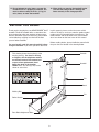
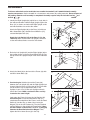
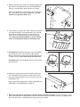
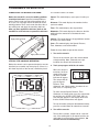
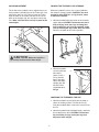
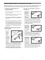
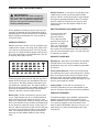
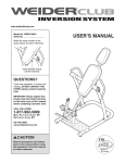
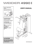
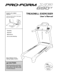
www.healthrider.com
Model No. HRTL01209.0
Serial No.
Write the serial number in the
space above for reference.
Serial Number Decal
QUESTIONS?
If you have questions, or if parts are
damaged or missing, DO NOT CONTACT THE STORE; please contact
Customer Care.
IMPORTANT: Please register this
product (see the limited warranty
on the back cover of this manual)
before contacting Customer Care.
1-888-922-4222
CALL TOLL-FREE:
Mon.–Fri. 6 a.m.–6 p.m. MT
Sat. 8 a.m.–4 p.m. MT
ON THE WEB:
www.healthriderservice.com
CAUTION
Read all precautions and instructions in this manual before using
this equipment. Save this manual
for future reference.
USERʼS MANUAL
TABLE OF CONTENTS
IMPORTANT PRECAUTIONS . . . . . . . . . . . . . . . . . . . . . . . . . . . . . . . . . . . . . . . . . . . . . . . . . . . . . . . . . . . . . . . . 2
BEFORE YOU BEGIN . . . . . . . . . . . . . . . . . . . . . . . . . . . . . . . . . . . . . . . . . . . . . . . . . . . . . . . . . . . . . . . . . . . . . . 3
ASSEMBLY . . . . . . . . . . . . . . . . . . . . . . . . . . . . . . . . . . . . . . . . . . . . . . . . . . . . . . . . . . . . . . . . . . . . . . . . . . . . . . 4
TREADMILL OPERATION . . . . . . . . . . . . . . . . . . . . . . . . . . . . . . . . . . . . . . . . . . . . . . . . . . . . . . . . . . . . . . . . . . . 6
MAINTENANCE AND TROUBLESHOOTING . . . . . . . . . . . . . . . . . . . . . . . . . . . . . . . . . . . . . . . . . . . . . . . . . . . . 8
EXERCISE GUIDELINES . . . . . . . . . . . . . . . . . . . . . . . . . . . . . . . . . . . . . . . . . . . . . . . . . . . . . . . . . . . . . . . . . . . 9
PART LIST . . . . . . . . . . . . . . . . . . . . . . . . . . . . . . . . . . . . . . . . . . . . . . . . . . . . . . . . . . . . . . . . . . . . . . . . . . . . . . 10
EXPLODED DRAWING . . . . . . . . . . . . . . . . . . . . . . . . . . . . . . . . . . . . . . . . . . . . . . . . . . . . . . . . . . . . . . . . . . . . 11
ORDERING REPLACEMENT PARTS . . . . . . . . . . . . . . . . . . . . . . . . . . . . . . . . . . . . . . . . . . . . . . . . . Back Cover
LIMITED WARRANTY . . . . . . . . . . . . . . . . . . . . . . . . . . . . . . . . . . . . . . . . . . . . . . . . . . . . . . . . . . . . . . Back Cover
IMPORTANT PRECAUTIONS
WARNING:
To reduce the risk of serious injury, read the following important precautions before using the treadmill. Before beginning this or any exercise program, consult your physician. This is especially important for persons over age 35 or persons with pre-existing health problems. Read all instructions before using this product. ICON assumes no responsibility for personal
injury or property damage sustained by or through the use of this product.
caught on the treadmill. Always wear athletic
shoes when using the treadmill; do not use
the treadmill with bare feet, wearing only
stockings, or in sandals.
1. It is the responsibility of the owner to ensure
that all users of the treadmill are adequately
informed of all warnings and precautions.
2. Use the treadmill only as described. This
treadmill is intended for in-home use only. Do
not use the treadmill in a commercial, rental,
or institutional setting.
9. Never insert any object into any opening on
the treadmill.
10. Always hold the handrails while using the
treadmill.
3. Place the treadmill on a level surface, with at
least 8 ft. (2.4 m) of clearance behind it and 2
ft. (0.6 m) on each side. Do not place the
treadmill on any surface that blocks air openings. To protect the floor or carpet from damage, place a mat under the treadmill.
11. Keep the treadmill indoors, away from moisture and dust. Do not put the treadmill in a
garage or covered patio, or near water.
12. Do not operate the treadmill where aerosol
products are used or where oxygen is being
administered.
4. Inspect and properly tighten all parts of the
treadmill regularly.
5. The roller guards must be 1/8 inch from the
rear roller (see the drawing on page 3). Adjust
the roller guards, if necessary.
13. Over exercising may result in serious injury
or death. If you feel faint or if you experience
pain while exercising, stop immediately and
cool down.
6. Keep children under age 12 and pets away
from the treadmill at all times.
14. Never remove the motor hood unless
instructed to do so by an authorized service
representative. Servicing other than the procedures in this manual should be performed
by an authorized service representative only.
7. The treadmill should be used only by persons
weighing 250 lbs. (113 kg) or less. Never
allow more than one person on the treadmill
at a time.
8. Wear appropriate clothing when exercising.
Do not wear loose clothing that could become
2
15. Do not attempt to raise, lower, or move the
treadmill until it is properly assembled. You
must be able to safely lift 25 lbs. (11 kg) to
raise, lower, or move the treadmill.
16. When folding or moving the treadmill, make
sure that the storage latch is holding the
frame securely in the storage position.
BEFORE YOU BEGIN
ing this manual, please see the front cover of this
manual. To help us assist you, note the product model
number and serial number before contacting us. The
model number and the location of the serial number
decal are shown on the front cover of this manual.
Thank you for selecting the new HEALTHRIDER® H10T
treadmill. The H10T treadmill offers a selection of features designed to make your workouts at home more
effective. And when youʼre not exercising, the treadmill
can be folded up, requiring less than half the floor
space of other treadmills.
Before reading further, please familiarize yourself with
the parts that are labeled in the drawing below.
For your benefit, read this manual carefully before
using the treadmill. If you have questions after read-
Console
This drawing shows the location(s) of the
warning decal(s). If a decal is missing
or illegible, call the telephone number
on the front cover of this manual and
request a free replacement decal.
Apply the decal in the location
shown. Note: The decal(s) may not be
shown at actual size.
Handrail
Pin
Hood
Walking Belt
Pin
Roller Guards
Rear Roller Adjustment Bolts
3
ASSEMBLY
To hire an authorized service technician to assemble the treadmill, call 1-800-445-2480. Assembly
requires two persons. Set the treadmill in a cleared area and remove all packing materials. Do not dispose of
the packing materials until assembly is completed. Assembly requires only the included hex key and
wrench
.
1. Identify the Right Upright (36), which has a single hole in
the indicated location. Hold the Right Upright against the
Base (14) as shown, and orient the Right Upright so the
two indicated holes are on the side shown.
1
36
37
Attach the Right Upright (36) to the Base (14) with two
M8 x 50mm Bolts (38), two M8 Curved Washers (37),
and two M8 Nylon Nuts (13).
38
Attach the Left Upright (35) to the Base (14) in the
same way. Make sure that the Left Upright is oriented
so the two indicated holes are on the side shown.
2. Raise the Left Upright (35) and the Right Upright (36) to
the position shown. Insert the Reed Switch Wire (6) into
the top of the Left Upright and pull it out of the indicated
hole.
Holes
37
2
14
13
37
Hole
Holes
35
13
38
37
6
35
36
Hole
3. Attach the Hood (28) to the front of the Frame (29) with
two M5 x 10mm Bolts (10).
4. See drawing 4a. Hold the front of the Frame (29)
between the Left Upright (35) and the Right Upright (not
shown). Align the holes near the front of the Frame with
one of the three sets of adjustment holes in the
Uprights. Insert a Pin (4) into each Upright and each
side of the Frame. Make sure that the Pins are fully
inserted at the same height.
Look under the Frame (29) near the Left Upright (35).
See drawing 4b. Locate the Reed Switch Clip (11)
attached to the underside of the Frame. Insert the Reed
Switch (6) into the Clip as shown. Next, locate the
Magnet (12) on the left Flywheel (9). Turn the Flywheel
until the Magnet is aligned with the Reed Switch. Move
the Reed Switch so that there is a 1/8 in. (3 mm) gap
between the Reed Switch and the Magnet. Then,
tighten the M4 x 12mm Screw (3) in the Clip.
4
3
28
10
29
10
4a
29
4
35
4b
12
9
1/8 in.
6
3
11
View from 29
below
5. Hold the Handrail (5) near the Left and Right Uprights (35,
36). Connect the Handrail Wire (2) to the Reed Switch
Wire (6). Insert the Wires down into the Left Upright.
5
Attach the Handrail (5) to the Uprights (35, 36) with four
M8 x 15mm Bolts (33) and four M8 Washers (34). Be
careful not to pinch the Wires (2, 6).
33 34
2
5
6
35
34
36
6. The Console (1) requires two “AAA” batteries (not included). Alkaline batteries are recommended. Press the indicated tab on the Battery Cover (27) and remove the
Battery Cover. Insert two batteries into the two battery
clips; make sure that the negative (–) ends of the batteries are touching the springs in the battery clips.
6
Batteries
1
Tab
27
7. See drawing 7a. Hold the Console (1) near the Handrail
(5). Connect the wire on the Console to the Handrail
Wire (2). Attach the Console to the Handrail with two M4
x 12mm Screws (3). Be careful not to pinch the wires.
7a
3
Make sure that the walking belt is properly tightened (see
SYMPTOM 2 and SYMPTOM 3 on page 8).
7b
1
1
2
See drawing 7b. Press the Battery Cover (27) back onto
the Console (1).
8. Remove the paper backing from the Adhesive Clip (30).
Press the Adhesive Clip onto the left side of the Frame
(29) in the indicated location. Press the Hex Key (20) into
the Adhesive Clip.
33
5
27
8
20
30
29
9. Make sure that all parts are properly tightened before you use the treadmill. To protect the floor or carpet,
place a mat under the treadmill. Note: If a part is not in the hardware kit, check to see if it is preattached to
one of the parts to be assembled. Extra hardware may be included.
5
TREADMILL OPERATION
LUBRICATING THE WALKING PLATFORM
The console features six modes:
Speed—This mode displays your speed, in miles per
hour.
Before the treadmill is used, the walking platform
should be lubricated. Open the included lubricant
packet. Reach under one side of the walking belt as
far as you can, and apply half of the lubricant to the
walking platform. Then, reach under the other side of
the walking belt and apply the remaining lubricant.
After you have applied the lubricant, walk on the
treadmill for a few minutes to spread the lubricant.
Distance—This mode displays the number of miles
you have walked.
Time—This mode displays the elapsed time.
Odometer—This mode displays the distance that the
walking belt has moved since the batteries were
changed.
Calorie—This mode displays the approximate number
of calories you have burned.
Apply lubricant here
Scan—This mode displays the Speed, Distance,
Time, Odometer, and Calorie modes.
Follow the steps below to operate the console.
1. Turn on the console.
Apply lubricant here
To turn on the console, press the console button
or begin walking. Note: If batteries were just
installed, the console will already be on.
STEP-BY-STEP CONSOLE OPERATION
Before the console can be operated, batteries must be
installed (see assembly step 6 on page 5). If there is a
thin sheet of plastic on the console, remove the plastic.
2. Track your progress with the six modes.
When the console is
turned on, the Scan
mode will be selected and the SCAN
indicator will appear.
SCAN Indicator
The console will display the Speed,
Distance, Time,
Odometer, and Calorie modes, for about six seconds each, in a repeating cycle.
To select only the Speed, Distance, Time,
Odometer, or Calorie mode, press the console button until only the SPEED, DIST, TIME, ODO, or
CAL indicator appears in the display. Make sure
that the SCAN indicator does not appear.
To reset all modes (except for the odometer mode),
press the console button for about three seconds.
3. Turn off the console.
To turn off the console, simple wait for a few minutes. If the walking belt is not moved and the console button is not pressed for a few minutes, the
console will turn off automatically.
6
INCLINE ADJUSTMENT
FOLDING THE TREADMILL FOR STORAGE
The incline of the treadmill can be adjusted to any of
three positions. Hold the front of the Frame (29), and
remove the two Pins (4). Raise or lower the Frame,
align the holes in the Frame with one of the sets of
holes in the Uprights (35, 36), and then re-insert the
Pins. Make sure both Pins are fully inserted at the
same height.
35
When the treadmill is not in use, it can be folded to
the compact storage position. CAUTION: You must
be able to safely lift 25 lbs. (11 kg) to raise, lower,
or move the treadmill.
1. Hold the treadmill with your hands in the locations
shown below. CAUTION: To decrease the possibility of injury, bend your legs and keep your
back straight. As you raise the treadmill, make
sure to lift with your legs rather than your back.
Raise the treadmill to the vertical position.
36
4
1
29
4
CAUTION:
Make sure both Pins
(4) are fully inserted at the same height.
2. Hold the treadmill
securely with your
left hand as
shown. Insert a
Pin (4) into the
hole in the right
side of the Right
Upright (36) and
into the Frame
(29) as far as it
will go.
2
29
36
4
LOWERING THE TREADMILL FOR USE
1. Hold the treadmill securely with your left hand as
shown in drawing 2 above. Pull out the Pin (4).
Pivot the treadmill down a few inches and re-insert
the Pin.
2. Hold the treadmill firmly with both hands, and lower
the treadmill to the floor. CAUTION: To decrease
the possibility of injury, bend your legs and
keep your back straight.
7
MAINTENANCE AND TROUBLESHOOTING
Most treadmill problems can be solved by following the steps below. Find the symptom that applies, and
follow the steps listed. If further assistance is needed, please see the front cover of this manual.
1. SYMPTOM: THE CONSOLE DOES NOT
FUNCTION PROPERLY
3. SYMPTOM: THE WALKING BELT SLIPS OR IS
OFF-CENTER
a. If the walking
belt slips
when walked
on, use the
hex key to turn
both rear roller
adjustment
bolts clockwise,
1/4 of a turn. When the walking belt is correctly
tightened, you should be able to lift each side of
the walking belt 2 to 3 in. (5 to 7 cm). Walk on the
treadmill for a few minutes. Repeat until the walking belt is properly tightened. Be careful to keep
the walking belt centered.
a. Replace the batteries in the console (see assembly step 6 on page 5).
b. Make sure that the reed switch is properly adjusted (see assembly step 4 on page 4).
c. Make sure that the handrail wire is plugged fully
into the wire on the console (see assembly step 7
on page 5).
d. The console, like most electronics, is susceptible
to static electricity build-up caused by certain
types of clothing or by the operation of the treadmill. If the display is blank or gives incorrect readings, apply an anti-static spray to the handrail.
Anti-static spray is available where laundry supplies are sold.
b. If the walking
belt has shifted to the left
side, use the
hex key to turn
the left adjustment bolt
clockwise, and
the right adjustment bolt counterclockwise, 1/4 of
a turn each. Be careful not to overtighten the
walking belt. Walk on the treadmill for a few minutes. Repeat until the walking belt is centered.
2. SYMPTOM: THE WALKING BELT DOES NOT
MOVE SMOOTHLY
a. If the walking belt is
Walking Belt
overtightened, performance
may be
reduced and
the walking
belt may be
2–3 in.
permanently
damaged.
Bolts
Using the
hex key,
turn both rear roller adjustment bolts counterclockwise 1/4 of a turn. When the tension of the
walking belt is correct, you should be able to lift
each side of the walking belt 2 to 3 in. (5 to 7
cm). Walk on the treadmill for a few minutes.
Repeat until the walking belt is properly tightened.
Be careful to keep the walking belt centered.
c. If the walking
belt has shifted to the right
side, use the
hex key to turn
the left adjustment bolt counterclockwise,
and the right adjustment bolt clockwise, 1/4 of a
turn each. Be careful not to overtighten the walking belt. Walk on the treadmill for a few minutes.
Repeat until the walking belt is centered.
8
EXERCISE GUIDELINES
WARNING:
Aerobic Exercise—If your goal is to strengthen your
cardiovascular system, you must perform aerobic
exercise, which is activity that requires large amounts
of oxygen for prolonged periods of time. For aerobic
exercise, adjust the intensity of your exercise until
your heart rate is near the highest number in your
training zone.
Before beginning
this or any exercise program, consult your
physician. This is especially important for
persons over age 35 or persons with preexisting health problems.
HOW TO MEASURE YOUR HEART RATE
These guidelines will help you to plan your exercise
program. For detailed exercise information, obtain a
reputable book or consult your physician. Remember,
proper nutrition and adequate rest are essential for
successful results.
To measure your heart
rate, exercise for at
least four minutes.
Then, stop exercising
and place two fingers on
your wrist as shown.
Take a six-second heartbeat count, and multiply
the result by 10 to find your heart rate. For example, if
your six-second heartbeat count is 14, your heart rate
is 140 beats per minute.
EXERCISE INTENSITY
Whether your goal is to burn fat or to strengthen your
cardiovascular system, exercising at the proper intensity is the key to achieving results. You can use your
heart rate as a guide to find the proper intensity level.
The chart below shows recommended heart rates for
fat burning and aerobic exercise.
WORKOUT GUIDELINES
Warming Up—Start with 5 to 10 minutes of stretching
and light exercise. A warm-up increases your body
temperature, heart rate, and circulation in preparation
for exercise.
Training Zone Exercise—Exercise for 20 to 30 minutes with your heart rate in your training zone. (During
the first few weeks of your exercise program, do not
keep your heart rate in your training zone for longer
than 20 minutes.) Breathe regularly and deeply as you
exercise–never hold your breath.
To find the proper intensity level, find your age at the
bottom of the chart (ages are rounded off to the nearest ten years). The three numbers listed above your
age define your “training zone.” The lowest number is
the heart rate for fat burning, the middle number is the
heart rate for maximum fat burning, and the highest
number is the heart rate for aerobic exercise.
Cooling Down—Finish with 5 to 10 minutes of
stretching. Stretching increases the flexibility of your
muscles and helps to prevent post-exercise problems.
EXERCISE FREQUENCY
Burning Fat—To burn fat effectively, you must exercise at a low intensity level for a sustained period of
time. During the first few minutes of exercise, your
body uses carbohydrate calories for energy. Only after
the first few minutes of exercise does your body begin
to use stored fat calories for energy. If your goal is to
burn fat, adjust the intensity of your exercise until your
heart rate is near the lowest number in your training
zone. For maximum fat burning, exercise with your
heart rate near the middle number in your training
zone.
To maintain or improve your condition, complete three
workouts each week, with at least one day of rest
between workouts. After a few months of regular exercise, you may complete up to five workouts each
week, if desired. Remember, the key to success is to
make exercise a regular and enjoyable part of your
everyday life.
9
PART LIST—Model No. HRTL01209.0
Key No. Qty.
1
2
3
4
5
6
7
8
9
10
11
12
13
14
15
16
17
18
19
20
21
22
1
1
3
3
1
1
10
2
1
4
1
1
4
1
2
2
2
1
1
1
2
2
Description
Key No. Qty.
Console
Handrail Wire
M4 x 12mm Screw
Pin
Handrail
Reed Switch/Wire
M5 x 20mm Bolt
Frame Cap
Front Roller/Flywheel
M5 x 10mm Bolt
Reed Switch Clip
Magnet
M8 Nylon Nut
Base
Base Pad
Roller Guard
Base Cap
Walking Belt
Walking Platform
Hex Key
Frame Foot
Rear Roller Adjustment Bolt
23
24
25
26
27
28
29
30
31
32
33
34
35
36
37
38
39
40
41
*
*
2
2
1
1
1
1
1
1
2
2
4
4
1
1
4
4
1
1
2
–
–
Description
R1209A
Rear Roller Washer
Frame Plate
Rear Roller
Wrench
Battery Cover
Hood
Frame
Adhesive Clip
Handrail Cap
Handrail Foam Grip
M8 x 15mm Bolt
M8 Washer
Left Upright
Right Upright
M8 Curved Washer
M8 x 50mm Bolt
Grommet
Warning Decal
Platform Cover
Lubricant Packet
Userʼs Manual
Note: Specifications are subject to change without notice. For information about ordering replacement parts, see
the back cover of this manual. *These parts are not illustrated.
10
EXPLODED DRAWING—Model No. HRTL01209.0
33
1
31
32
40
3
10
31
28
32
23
22
30
24
20
7
25
21
7
26
24
23
22
36
4
41
19
29
16
34
33
35
10
10
6
27
2
5
34
R1209A
39
6
11
3
12
13
37
13
37
9
18
7
7
41
4
8
7
13
7
10
37
7
16
15
17
21
38
7
17
11
8
7
14
15
7
38
4
ORDERING REPLACEMENT PARTS
To order replacement parts, please see the front cover of this manual. To help us assist you, be prepared to provide the following information when contacting us:
• the model number and serial number of the product (see the front cover of this manual)
• the name of the product (see the front cover of this manual)
• the key number and description of the replacement part(s) (see the PART LIST and the EXPLODED
DRAWING near the end of this manual)
LIMITED WARRANTY
IMPORTANT: You must register this product within 30 days of the purchase date to avoid added
fees for service needed under warranty. Go to www.healthriderservice.com/registration.
ICON Health & Fitness, Inc. (ICON) warrants this product to be free from defects in workmanship and
material, under normal use and service conditions, for a period of ninety (90) days from the date of purchase.
This warranty extends only to the original purchaser. ICONʼs obligation under this warranty is limited to
repairing or replacing, at ICONʼs option, the product through one of its authorized service centers. All
repairs for which warranty claims are made must be preauthorized by ICON. If the product is shipped to
a service center, freight charges to and from the service center will be the customerʼs responsibility. For
replacement parts shipped while the product is under warranty, the customer will be responsible for a minimal handling charge. For in-home service, the customer will be responsible for a minimal trip charge. This
warranty does not extend to any damage to a product caused by or attributable to freight damage, abuse,
misuse, improper or abnormal usage, or repairs not provided by an ICON authorized service center; to
products used for commercial or rental purposes or as store display models; or to products transported
or purchased outside the US. No other warranty beyond that specifically set forth above is authorized by
ICON.
ICON is not responsible or liable for indirect, special, or consequential damages arising out of or in connection with the use or performance of the product; damages with respect to any economic loss, loss of
property, loss of revenues or profits, loss of enjoyment or use, or costs of removal or installation; or other
consequential damages of whatsoever nature. Some states do not allow the exclusion or limitation of incidental or consequential damages. Accordingly, the above limitation may not apply to you.
The warranty extended hereunder is in lieu of any and all other warranties, and any implied warranties of
merchantability or fitness for a particular purpose are limited in their scope and duration to the terms set
forth herein. Some states do not allow limitations on how long an implied warranty lasts. Accordingly, the
above limitation may not apply to you.
This warranty gives you specific legal rights. You may also have other rights that vary from state to state.
ICON Health & Fitness, Inc., 1500 S. 1000 W., Logan, UT 84321-9813
Part No. 294582 R1209A
HealthRider is a registered trademark of ICON IP, Inc.
Printed in USA © 2009 ICON IP, Inc.