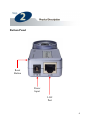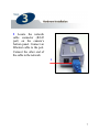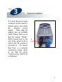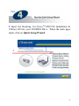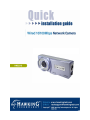
1
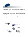
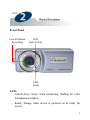
1
Step 1: Check Contents & Installation Requirements
3
Step 2: Physical Description
5
Step 3: Hardware Installation
7
Step 4: Run the Quick Setup Wizard
9
Step 5: Viewing & Tips
24
2
Congratulations on the purchase of your new Hawking NetVisionTM HNC210 Wired 10/100Mbps Network Camera. The
HNC210 is a high performance standalone camera system that
provides an ideal solution for remote monitoring, surveillance, or
sending live video over the Internet. The camera offers a broad
array of applications and can be used to monitor various critical
locations such as homes, offices, and other industrial and public
areas. Please read this quick installation guide carefully before
beginning your installation.
General Installation:
3
4
Front Panel
Lens & Manual
Focus Ring
LED:
Link/Activity
LED:
Ready
LEDs
- Link/Activity: Green when monitoring; flashing for video
transmission/reception
-
Ready: Orange when device is powered on & ready for
access
5
Bottom Panel
Reset
Button
Power
Input
LAN
Port
6
1 Locate the network
cable connector (RJ-45
port) on the camera’s
bottom panel. Connect an
Ethernet cable to the port.
Connect the other end of
the cable to the network.
1
7
2 Locate the power input
connector on the camera’s
bottom panel, and attach
the
external
power
supply. Then, plug the
adapter into an available
outlet. Please check to see
that the orange “Ready”
LED located next to the
lens of the camera is lit to
ensure that the camera is
powered on. (To ensure
that there is a network
connection, please check
to see that the green
“Link/Activity” LED is lit
or flashing.)
2
8
1 Insert the Hawking Net-VisionTM HNC210 Installation &
Utilities CD into your CD-ROM Drive. When the main page
loads, click on Quick Setup Wizard.
1
9
2
2 The Setup Wizard will search for similar cameras available on
your local area network. A “similar” camera will have the same
code of four letters at the beginning of its serial number. This
code is “HEMT” and can be found on either the right or left
panel of the box, or on the label on the bottom of the camera.
10
Each available camera will be displayed in the camera list
with its MAC address, current default IP address, and model
number. (NOTE: The Setup Wizard may display an IP
address for the camera that is already consistent with your
network [LAN] settings, rather than the default one.) In the
camera list, click on the camera you would like to configure so
that it is highlighted blue, and then click Next. (If you are
unsure about which camera you would like to configure, you
can compare its MAC address displayed in the camera list to
the one printed on the label on the underside of the camera.)
NOTE: If the camera list does not display any available
cameras, you should:
a.
b.
Click on the “Rescan Camera” button, and
Make sure that all available similar network cameras are
connected properly to the network.
If neither option above is successful, you can also perform a
factory default reset by holding down the “Reset” button on
the back panel of the camera for at least five seconds. Then,
allow about 45 seconds to one minute for the camera to
complete the reboot process. This should easily resolve the
issue.
11
3 Next, the login username and password screen will appear.
Please type in the default login and password and then press
“OK”. The default values are:
Login: admin
Password: 1234
If you have already set a username and password, enter them
and press “OK”.
3
12
4 The Setup Wizard will try to determine your network
settings. If a DHCP server is present on your network, the
Wizard will obtain your network settings and automatically
configure your network camera to operate on your LAN by
returning network settings that are consistent with your
network.
If no DHCP server is present, the Wizard will poll your PC’s
internal network settings and suggest an appropriate static IP
address in the “Manual IP” section to assign to the network
camera. If you do not wish to use the suggested IP address,
you may change your IP settings in the “Manual IP” section
only.
NOTE: Typically, your Gateway address is the IP address of
your network’s router or Internet gateway. The Wizard will
try and automatically fill in this address for you based on your
PC’s current settings.
Please click Next once your computer has found the
appropriate IP settings.
NOTE: If you are unfamiliar with how to manually set an IP
address, a detailed example is provided at the end of this section.
13
4
14
5 To protect your camera from unauthorized access and use,
you will need to change the Admin Password, which is
“1234” by default. The password can have a maximum of
four characters. Confirm the new password by typing it again
identically in the “Reconfirm” field.
Click Next once you have confirmed your new password.
5
15
6 The following status page will appear. It will display a
summary of the changes you have made to the network
camera’s settings. If all the settings are correct, click Next to
continue.
6
16
7 The setup process has now been completed. Please briefly
review the text on the page before clicking on Reboot. After
clicking Reboot, the Setup Wizard will close. Please allow about
45 seconds to one minute for the camera to reboot. After the
camera has finished rebooting, you can type in its new IP address
in your web browser to begin accessing the camera.
11
17
Example on How to Set the IP Address Manually
The example shown here illustrates how to manually set an IP
address using the Windows XP operating system. However, the
procedure is similar for all other versions of Windows.
When setting an IP address, you must make sure that the address
you specify has the same first three octets (or segments) as the
other devices on your LAN. In the figures on the previous pages,
the camera has the following IP address: 10.1.1.144. The address
is comprised of four segments separated by periods. Each
segment is called an “octet”. All devices on your LAN must have
the same first three octets, in this case “10.1.1”. Therefore, all
devices on your LAN must have IP addresses of the form
“10.1.1.x”, where “x” is a number between 0 and 254. When
setting the IP address for the network camera, it is recommended
(but not required) that you choose a number towards the end of
the range between 0 and 254, excluding 254 itself. (Occasionally,
the number 254 is used as the final segment for the default IP
address of other devices.) Selecting a number towards the end of
the range (preferably between 200 and 250) will help avoid
conflicts with IP addresses that are already being used by other
devices on the LAN.
To determine the common octets/segments for your LAN
settings, follow the steps outlined in the next two pages.
18
a. Click on Start in the bottom left corner of your screen.
Then click on My Network Places.
a
19
b. Click on View Network Connections.
b
20
c. In the Network Connections window, you should see an
icon titled Local Area Connection (or something similar).
You can access this icon in two ways: a. by clicking or doubleclicking on it, or b. by right-clicking on it and then clicking on
Status from the resulting menu.
c
21
d. A window with the title Local Area Connection Status
(or something similar) will appear. (See the figure on the
following page.) Click on the Support tab. Under the
heading Address Type, you will find an IP Address line and
a Default Gateway line. These two lines will have IP
addresses with the first three octets in common.
Use this
information to set the IP address for your network camera.
You will use these same three octets as the first three octets
for the IP address of your network camera. The final octet
will be a number between 0 and 254.
22
d
23
•
You can access and view your network camera’s images via
a web browser by typing “http://IPAddressofCamera” in
the address bar.
•
You can also use the included software application to view,
record, and playback the network camera’s images.
•
The example illustrated in the previous section “Step 4: Run
the IP Setup Program” deals with setting up an IP address to
view the network camera within your LAN. For an example
of how to view your network camera outside of your existing
LAN via the Internet, please refer to the section in the user’s
manual titled “How to View Your Camera via the
Internet”.
•
If the image is blurry, this is most likely because the camera
lens is out of focus. To focus the lens, gently rotate the lens
in either direction until the desired level of focus is reached.
Please Note: Do not aggressively turn or overturn the lens,
as this could lead to an unscrewing or damaging of the lens.
•
It is highly recommended that you install the network
camera(s) before placing them in the desired physical
location.
24