1
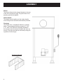
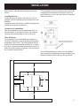
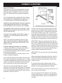
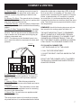
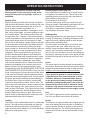
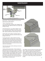
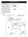
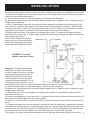
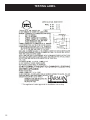
Installation & Operating Manual
The Harman SF 250 Coal Stove
R3
SAFETY NOTICE
Please read this entire manual before you install and use your new room heater. Failure
to follow instructions may result in property damage, bodily injury, or even death.
FOR USE IN THE U.S. AND CANADA. not SUITABLE FOR INSTALLATION IN MOBILE HOMES
IF THIS HARMAN STOVE IS NOT PROPERLY INSTALLED, A HOUSE FIRE MAY RESULT. FOR YOUR SAFETY, FOLLOW INSTALLATION DIRECTIONS.
CONTACT LOCAL BUILDING OR FIRE OFFICIALS ABOUT RESTRICTIONS AND INSTALLATION INSPECTION
REQUIREMENTS IN YOUR AREA.
Contact your local authority (such as municipal building department, fire department, fire
prevention bureau, etc.) to determine the need for a permit.
Cette guide d’utilisation est disponible en francais. Chez votre concessionnaire de Harman
home heating.
save these instructions.
R1
Part # 3-90-70738
Table of Contents
Safety Considerations..........................3
Assembly..............................................4
Installation............................................5
Chimney & Venting...............................6
Operating Instructions..........................8
Preventive Maintenance.......................9
Optional Hot Water Coil.......................10
Testing Label.......................................12
Warranty..............................................13
Safety Considerations
CAUTION
l
l
l
l
l
Keep Children Away
May Cause Serious Burns
All Surfaces of stove are hot. Do not touch.
Keep children away.
Serious burns will result if touched.
Fuel/Firing Warnings
Danger
Do not use chemicals or fluids to start or
“freshen up” a fire. Severe body burns or a
fire in your home could result.
Do not burn garbage, gasoline, thinners,
drain oil or engine oil, kerosene, or fuel oil,
etc. An explosion, a house fire, or personal
injury could result. Keep all such liquids well
away from the stove while in use.
Curing Paint
During the first few hours of burning, a blue smoke
will be observed rising from the painted surface of the
stove. It is advisable to increase the amount of fresh
air (open window) in the room during this breaking-in
period. Do not be alarmed, this is normal and does not
cause harm.
Mobile Homes
This Harman Stove is not approved for installation in
mobile/manufactured homes.
SPECIAL WARNING: NEVER OPERATE YOUR
STOVE WITH THE FIRE OR ASH DOOR OPEN!
Keep Ash Pan Empty.
Excessive ash buildup will block the airflow around
the grates. This, and only this, will cause the grates to
warp and sag. Neglect is not covered by your stove’s
warranty.
Never burn materials other than coal. A chimney fire or heat exchanger failure could result.
This includes large amounts of corrugated
boxes, wood shavings, paper scraps, garbage
or other burnable materials.
If chimney pipes or connectors reach 500 degrees fahrenheit (maximum temperature), the
stove is being over-fired. We recommend the
purchase of a Magnetic Temperature Gauge
to monitor the stove and stack temperatures
relative to the amount of draft the customer
permits the stove to operate.
It has been verified that creosote will ignite
at 650 degrees fahrenheit. It is the owner’s
responsibility to follow these recommendations.
This stove consumes air when it is burning.
if your house is tightly sealed and insulated,
it is advisable that a window in the vicinity be
opened slightly while the stove is burning.
Information contained in this manual is manufacturer’s recommendations and if there is
any difference between our recommendations
and local code requirements, we suggest following local code requirements.
Assembly
Blower
The blower slides into the channel bracket on the rear
of the stove as shown at right. Plug the blower into a
properly grounded receptacle.
Shaker Handle
The shaker handle installs onto the shaker handle
mount using the two hex-bolts and washers provided.
Firebricks
The SF250 uses 14 “standard” firebricks, as shown
below. These standard firebricks measure 9” X 4½”
X 1¼” each. The firebricks are already installed in
the stove but can be removed to lighten the stove for
moving. The doors can also be removed by simply lifting them off of the hinges.
Firebrick Diagram
Installation
WARNING: This stove must be installed in accordance with all state and local building code requirements.
Locating the stove
Locate the stove as close to the chimney or flue as
possible, while still maintaining the clearances to combustibles.
Locate the stove where there is sufficient air supply for
ventilation and proper combustion.
Adjustable Leveling Feet
To accomodate an un-even hearth surface, the SF250
is equipped with adjustable leveling feet. Each foot
can be turned in or out of the leg to lower or raise that
corner of the stove.
Clearance to Combustibles
Safe stove clearance to combustible walls is 24” to
the rear and 36” to the sides and front. Do not place
furniture and the like directly in front of the stove.
Floor Protection
Floor protection for a combustible floor should consist of 3/8” millboard or a stove board providing equal
protection(k=.84, R=.45). The floor protection should
extend 8” to the rear and either side and 16” in front of
the stove. The floor protection should also extend 2” to
either side of the chimney connector, to the wall where
the connector enters the flue.
Turn the round foot in or out to
level each corner of the stove.
It is recommended that you have your unit installed
and serviced by professionals who are certified by the
National Firplace Institute (NFI) as NFI Specialists.
36”
Floor Protection
8”
24”
16”
8”
Floor Protection
8”
36”
Chimney & venting
Types Of Chimneys
The chimney is one of the most important, yet most
neglected and misunderstood portions of any solid
fuel burning stove installation. Do not connect this
stove to a chimney flue serving another heating device.
THE STOVE MUST BE CONNECTED TO ITS OWN
TILE-LINED FLUE. A MINIMUM FLUE SIZE OF 8” X
8” IS NECESSARY FOR PROPER OPERATION.
UNDER NO CIRCUMSTANCES SHOULD A MANUAL
FLUE DAMPER BE INSTALLED IN THE SMOKE
PIPE BETWEEN THE STOVE AND THE CHIMNEY.
NO DAMPER, HEAT SAVER OR AUTOMATIC VENT
DAMPER DEVICE SHOULD BE INSTALLED IN OR
ON THE SMOKE PIPE.
CAUTION: THE CHIMNEY MUST BE A CLASS “A”
CHIMNEY, IN GOOD OPERATING AND CLEAN
CONDITION.
NOTE: THE USE OF ALUMINUM TYPE “B” GAS
VENT FOR SOLID FUELS IS UNSAFE AND PROHIBITED BY THE NATIONAL FIRE PROTECTION
AGENCY CODE.
There are three types of class “A” chimneys:
1. Masonry with tile liner, to include brick or stone. It
must be supported on grade level foundation.
2. Insulated, manufactured chimney, listed or certified
by a national test agency.
3. Triple-wall metal class “A” chimney, listed or certified by a national test agency.
If your masonry chimney has not been used for some
time, have it inspected by a qualified person. If a listed
or certified manufactured chimney is to be used, make
certain it is installed in accordance with the manufacturer’s instructions and all local and state codes.
The three foot, two foot, ten foot rule
In order to have a properly operating solid fuel heating system, the chimney must be capable of providing the necessary draft. The minimum required draft
is .06 inches of water column (W.C.). This must be
measured using a draft gauge. If the chimney cannot
supply this constant draft, the stove will not operate
properly. A barometric damper may be used and properly adjusted to compensate for excessive draft only.
IMPORTANT: When you measure the the draft, the
stove must be operating with sufficient time given for
the stove and chimney to warm. Burn for at least thirty
minutes. The draft reading is best taken 18” up from
the center of the flue outlet, in the connector pipe. Drill
a hole in the pipe for the meter tube, and fill it with a
screw or silicone when done with the test.
IMPORTANT: The connector pipe must be 24 gauge
or thicker.
When connecting the flue pipe to the stove, the first
section should be installed inside the stove collar. It
should be secured to the collar with, at least, three
screws or rivets.
Do not pass the connector pipe through a wall or
ceiling without first checking with your local codes. If
allowed, use only approved pass-thru methods.
The minimum recommended height for solid fuel
chimneys is 16 feet from the stove collar. The chimney
NOTE: All horizontal runs of venting should have a 1/4
must be two feet higher than anything within ten feet.
It also must extend three feet above the point where it inch of rise per foot of length.
intersects or exits the roof line.
Use no more than two 90° elbows in the connector.
If a barometric damper is needed, to compensate for
excessive draft, install it only in a vertical section of
vent pipe.
Chimney & venting
Possible causes of insufficient draft;
A. Chimney Leaks - Air leaking in around a loose fitting cleanout door, flue pipe joints and/or seams not
secured, improper plug openings or defective masonry.
B. Chimney Too Short - The general rule for chimneys;
16 feet tall, three feet above the roof exit, and two feet
taller than anything within ten feet.
C. Blocked Chimney - Have the chimney cleaned and
inspected prior to installation and before each heating
season.
D. Trees Or Other Topographical Barriers - Impeding
on the chimney’s operation or causing a down draft
situation. This can also be caused by adjacent buildings or another roof of the same structure giving air
currents a downward swirl.
NOTE: The chimney on the illustrated house is too
low, it should be raised to compensate for down draft
potential.
dimensions of the liner be at least as large as the appliance flue outlet and no larger than 125% of the collar for a round flue. An example, a 8” flue collar is 50
square inches. Increased by 25% would be 63 square
inches, or approximately a 9” round flue. In general
for round liners, it is recommended that they not be
increased by more than one inch from that of the stove
collar. This will help ensure proper draft with the lower
flue temperatures.
REMEMBER; A solid fuel burning stove can only perform as well as its venting system will allow it to.
THE MOST IMPORTANT THING TO REMEMBER
ABOUT CHIMNEYS IS THEIR NEED FOR MAINTENANCE AND CLEANING. IF A CHIMNEY IS NOT
CLEANED ON A FREQUENT BASIS, IT WILL AFFECT THE DRAFT AS WELL AS BEING A CONTRIBUTING CAUSE TO A POSSIBLE CHIMNEY FIRE.
Wind direction
IF YOU HAVE A CHIMNEY FIRE:
1. GET EVERYONE OUT OF THE HOUSE.
2. CALL THE FIRE DEPARTMENT.
3. CLOSE THE DRAFT CONTROL KNOBS ON THE
STOVE.
DO NOT USE THE CHIMNEY UNTIL IT HAS BEEN
THOROUGHLY CLEANED AND INSPECTED BY A
QUALIFIED PERSON.
E. Chimney Size - The chimney can not be smaller
than the flue exit from the appliance. Too large of a
chimney could stay too cool to promote adequate
draft.
F. Chimney Offsets - Offset chimneys should be
avoided. The offset area can collect debris and cause
a blockage.
G. Elbow restrictions - There should be no more than
two 90° elbows or the equivalent used in connecting
the stove to the chimney flue.
H. Shared Flue - No more than one appliance shall
vent into a single flue.
The most common cause of poor draft is an improperly sized flue liner. It is recommended that the inside
operating instructions
The SF250 is approved for use with coal only.
Burning wood or other such fuels in this stove,
except for the purpose of igniting a coal fire, is
prohibited.
Starting A Fire
Begin by opening the draft control knobs on both the
load door and the ash door. Open both doors. Be sure
all items have been removed from the ash pan (i.e.
touch-up paint, warranty registration, etc...)
Place aproximately eight sheets of newspaper, crumbled, on top of the grates. Lay some kindling on top of
the crumbled paper. This kindling should be dry and
no larger than 3/4 in. diameter. It should be layered in
a criss-cross fashion to allow good air flow. Now place
some slightly larger pieces of wood (about 2” diameter) on top of the kindling. Using a match or grill lighter, ignite the paper at the bottom just inside the door.
Close both doors and allow the kindling and larger
wood to catch fire. After around five minutes, open the
load door slightly, for a few seconds and then open
completely. This is a good practice to get into as it
will allow any smoke and gases to clear away from
the door opening. Add small compact pieces of wood
when the kindling is burning hot. When a substantial
bed of hot wood coals is established, start adding
coal in small amounts at a time. Allow a few minutes
between coal loadings to be sure that what you’ve
added is ignited. You can keep the ash door open
through this process, but NEVER LEAVE THE STOVE
UNATTENDED WITH A DOOR OPEN. Once you have
a bed of burning coal, you can load coal into the stove
to the top of the firebricks. Always make sure there is
some flame showing through the coal. This will ensure
the gases are being burned and not accumulating in
the firebox. After a good coal ignition, set the draft
controls on the load door to about 1/4 turn open. The
draft control on the ash door is used to control the rate
of burn. After starting a fire, keep it about 2 full turns
open for about 30 minutes. Then, adjust further closed
to the proper output level. Normal operation will be
between cracked and one turn open. Since coal responds slowly to draft adjustments, make only small
adjustments and allow time in between.
Loading
Coal should only be added when there is a reasonably
hot fire. The coal bed should be bright and vigorous.
If the fire is burning hot and there is a deep bed of
coals, full loads can be added. If it is not as described,
add coal in small batches only.
Increasing Heat From A Low Fire
Every effort should be made not to let a coal fire burn
so long that it has started to die. This will cause the
reloading process to be much longer, and there is a
good posibility of losing the fire.
Do not shake or stir a low fire.
Open the draft control all the way until the fire gets
as hot as possible. Start adding small batches of coal
and follow the instructions for starting a fire.
Once there is a good bed of burning coals, the grates
may be shaken to remove ashes.
Shaking Ashes
Shaking should be done only when there is a hot fire
burning. The frequency of shaking will depend on the
degree of burning. Shaking should be done at least
once per day, preferably twice.
The best results from shaking will occur when short
choppy strokes are used, rather than long, even
strokes. Grasp the shaker handle with one hand and
shake it, only moving the actual handle 1/2 inch or
less. Do this until you start to see hot coals falling into
the ash pan, then stop. Do not rock the grates, as this
will allow burning coal to fall through, and you’ll lose
the fire.
Ashes
The ashes should never be allowed to accumulate in
the ash pan. Excess ash will block the required airflow
through the grates and cause them to warp and sag.
Neglect is not covered by your stove’s warranty.
Ashes should be placed in a metal container with
a tight fitting lid. This closed container of ashes
should be placed on a noncombustible floor or
on the ground, well away from any combustible
materials, pending final disposal. If the ashes are
disposed of by burial in soil, or otherwise locally
dispersed, they should be retained in the closed
container until all cinders have thoroughly cooled.
Fuel
The SF250 is approved for burning anthracite coal.
Pea, Nut, and Stove sized coal are all suitable.
Grates
The functions of a grate system are to support the fuel
load, while allowing air flow to the fire in a balanced
amount. Another function is to allow for ash removal
without losing the fire. The SF250 grate system provides for all of this and can be removed with no tools
required.
Maintenance
SHAKER
HANDLE
(external)
GRATES
SHAKER
BAR
GRATE LINK
Close-up view of grate system components
Periodic and Normal Everyday Maintenance
Blower Motor- Clean periodically to remove pet hair
and lint from the intake and fan.
Grates- Keep ash pan empty.
Spiral Chamber Cleanout
CAUTION: BEFORE CLEANING THE CHIMNEY AND
SMOKE PIPE, BE SURE THE FIRE IS OUT AND THE
STOVE IS COOL.
Avoid Chimney Fires. On a regular schedule, check
for creosote and soot buildup in the chimney, smoke
pipe, and spiral chamber. These areas must be kept
clean. Keep a professional chimney sweep in mind.
Steel brushes are the safest for cleaning metal surfaces. Salt solutions and some chemical cleaners may
damage the flue liner.
Cleanout Plate Removed
To clean the chimney, obtain a stiff brush with an
extendable handle. Insert the brush into the chimney
from the top. Continue brushing and sweeping downward until the entire length of the chimney is cleaned.
After cleaning the chimney, any debris will be at the
bottom by the clean-out door. Open the clean-out and
vacuum the loose debris.
Clean the smoke pipe, from the chimney to the stove,
using a metal brush.
Cleaning of the spiral chamber - Remove clean-out
plate from the front of the stove. Using a 3/4” wrench,
loosen the clean-out bolt approximately 2 turns. Slide
the clean-out plate to one side and remove it from the
opening. Scrape the spiral chamber with a putty knife
or similar tool. The residue will fall down to the bottom of the chamber and can be removed through the
flue opening on the back of the stove by means of a
vacuum cleaner or a small scoop.
In the firebox, remove all ashes and vacuum the entire
firebox. Inspect and replace any cracked firebricks.
Since coal and coal ashes will draw moisture, it is
important to thoroughly clean the firebox at the end of
the heating season. Some users apply a thin coating
of oil or other rust inhibitor to the inside workings, over
the summer. The main thing is that you remove all of
the ash.
Water coil option
Water Coil Installation
Use a hole saw and the template supplied with the coil to make two holes
through the side wall of the stove. Keep
the coil holes above the firebrick, and
away from the loading door. Place one
of the supplied nuts on each leg of the
coil. Place the coil through the holes in
the stove, and adjust the nuts so that the
pipes stick out about 1¼” to 1½” from
the sidewall of the stove. Put flat washers and nuts on the outside, and tighten
within ¼ inch. Place fiberglass gasket
around each pipe at the washers and
tighten securely. You are now ready to
run pipes according to one of the following examples.
EXAMPLE 1: Thermo-siphon
Method. (less than 10 feet.)
10
Water coil option
Example 1: Thermo-siphon Method. This is the simplest and most economical method, providing the existing
water heater (storage tank) is within 10 feet of the stove. The water inlet, where the Temp/Pressure relief valve
is located, must be higher than the top leg of the water coil. The storage tank should be elevated, if necessary,
to allow for proper thermo-siphon action.
A). Turn off the water heater and the water supply to it. Drain the tank completely.
B). Remove the Temp/Pressure relief valve and discard. Install a short ¾” nipple and tee (1) along with a new
Temp/Pressure relief valve.
C). Run ¾” copper tubing, along with the necessary fittings, between the storage tank and the top leg of the
coil. Install a ¾” vent elbow and automatic “float type” air vent (2) in the high point of the line. Within two feet
of the top leg of the coil, install a 150 lb. pressure relief valve (7). Run ¾” tubing from the release exit of both
relief valves, downward (3) so that the hot water may escape in the event of over-heating.
D). Remove the drain valve, at the bottom of the storage tank. Install a ¾” nipple and tee, and reinstall the
drain valve to the tee (4). Run ¾” copper tubing, with the necessary fittings, between the drain/tee combination
and the lower leg of the coil.
After all of the connections are completed, you can refill the tank. Restore
power to the water heater ONLY after
the tank has been completely refilled.
EXAMPLE 2: Circulator
Method. (more than 10 feet.)
Example 2: Circulating pump method.
Used when the distance is more than
ten feet or when the stove is on a higher
level than the existing water heater. In
addition to a circulator, you may want
to add a aquastat to control the pump
according to water temperature. This is
not necessary if the circulator is left run
continuously. Another option is a gate valve placed near the circulator to control the rate of flow.
A). Turn off the water heater and the water supply to it. Drain the tank completely.
B). Remove the Temp/Pressure relief valve and discard. Install a short ¾” nipple and tee (1) along with a new
Temp/Pressure relief valve.
C). Remove the drain valve, at the bottom of the storage tank. Install a ¾” nipple and tee, and reinstall the
drain valve to the tee (4).
D). Install a circulating pump (6) as shown. Run ¾” copper tubing from the circulator to the lower leg of the coil.
This is where the optional gate valve (5) can be installed.
E). Install a ¾” tee and a 150 lb. pressure relief valve (7) in the top leg within 2 feet of the top outlet of the water coil.
F). Complete the copper line by running it back to the tee at the top of the water tank, making sure to install a
vent elbow and automatic air vent (2) at the high point of the line. The optional aquastat can be installed in this
line a maximum of six feet from the stove. The aquastat must be a “close on temperature rise” type and must
be wired and set to turn on the circulator when the water temperature reaches 120˚ Farenheit.
The system is now ready to be refilled and power restored to the water heater ONLY after the tank is filled. 11
testing label
* This appliance is also approved for installation into a shop
12
13
14
Notes
15