1
AVR 4500 Audio/Video Receiver
OWNER’S MANUAL
®
Power for the Digital Revolution™
Table of Contents
3
4
4
5
7
9
11
14
15
15
15
16
18
19
19
20
20
20
20
21
21
23
24
24
24
25
26
26
27
29
29
31
31
31
32
32
32
33
33
33
33
34
35
35
35
35
36
36
37
37
37
38
38
39
40
40
40
40
41
41
41
41
42
42
42
42
43
43
Introduction
Safety Information
Unpacking
Front Panel Controls
Front Panel Information Display
Rear Panel Connections
Main Remote Control Functions
Zone II Remote Control Functions
Installation and Connections
Audio Connections
Video Connections
SCART A/V Connections
System and Power Connections
Speaker Selection
Speaker Placement
System Configuration
First Turn On
Using the On-Screen Display
Settings to be Made Individually
for Each Input In Use
Input Setup
Speaker Setup
Surround Setup
Adjustments for Other Inputs
Settings Keeping Independent
from the Input Selected
Delay Settings
Night Mode Settings
Output Level Adjustment
Using EzSet
Manual Output Level Adjustment
Operation
Surround Mode Chart
Basic Operation
Source Selection
Controls and Use of Headphones
Surround Mode Selection
Digital Audio Playback
Dolby Digital
DTS
PCM Audio Playback
MP3 Audio Playback
Selecting a Digital Source
Digital Status Indicator
Night Mode
Tape Recording
Front Panel Input/Output Connections
Output Level Adjustment
With Source Signals
6/8-Channel Direct Input
Memory backup
Advanced Features
Display Brightness
Turn-On Volume Level
Semi-OSD Settings
Full-OSD Time Out Adjustment
Multiroom Operation
Tuner Operation
Basic Tuner Operation
Station Selection
Preset Tuning
RDS Operation
RDS Tuning
RDS Display Options
Program Search
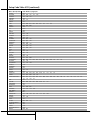
Programming the Remote
Programming the Remote with Codes
Direct Code Entry
Auto Search Method
Code Readout
Learning Codes
2 TABLE OF CONTENTS
43
Erasing Learned Codes
44
Macro Programming
45
Programmed Device Functions
45
Volume Punch-Through
46
Channel Control Punch-Through
46
Transport Control Punch-Through
46
Reassigning Device Control Selectors
47
Resetting the Remote Memory
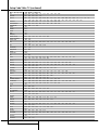
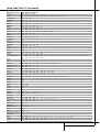
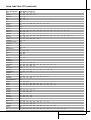
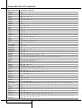
48 Function List
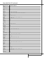
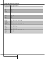
50 Setup Code Tables
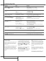
68 Troubleshooting Guide
68
Processor Reset
69 Technical Specifications
Declaration of Conformity
We, Harman Consumer International
2, route de Tours
72500 Château-du-Loir,
FRANCE
declare in own responsibility, that the product
described in this owner’s manual is in compliance
with technical standards:
EN 55013/6.1990
EN 55020/12.1994
EN 60065:1993
EN 61000-3-2/4.1995
Daniel Moyano
Harman Kardon Europe A/S
11/01
Typographical Conventions
In order to help you use this manual with the remote control, front-panel controls and rear-panel
connections, certain conventions have been used.
EXAMPLE – (bold type) indicates a specific remote control or front-panel button, or rear-panel
connection jack
EXAMPLE – (OCR type) indicates a message that is visible on the front-panel information display
1 – (number in a square) indicates a specific front-panel control
0 – (number in a circle) indicates a rear-panel connection
0 – (number in an oval) indicates a button or indicator on the remote
A – (letter in a square) indicates an indicator in the front-panel display
å – (letter in an oval) indicates a button on the Zone II remote
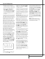
Introduction
Thank you for choosing Harman Kardon!
With the purchase of a Harman Kardon
AVR 4500 you are about to begin many years of
listening enjoyment. Designed to provide all the
excitement and detail of movie soundtracks and
every nuance of musical selections, the
AVR 4500 is truly a multichannel receiver for the
new millennium. In addition to the traditional
5.1 digital decoding modes such as Dolby Digital
and DTS, it offers the latest advancements in
surround technology such as Dolby Pro Logic II,
the full suite of DTS-ES 6.1 modes, DTS Neo:6
and the latest 7.1 channel versions of Harman's
own Logic 7 technology.
The AVR 4500 has been engineered so that it is
easy to take advantage of all the power of its
digital technology. On-screen menus, fully color
coded connection jacks and terminals and our
exclusive EzSet™ remote make installation fast
and simple. However, to obtain the maximum
enjoyment from your new receiver, we urge you
to read this manual. A few minutes spent learning the functions of the various controls will
enable you to take advantage of all the power
the AVR 4500 is able to deliver.
If you have any questions about this product, its
installation or its operation, please contact your
retailer or custom installer. They are your best
local sources of information.
Description and Features
The AVR 4500 is among the most versatile and
multifeatured A/V receivers available, incorporating a wide range of listening options. In addition
to Dolby Digital and DTS decoding for digital
sources, a broad choice of surround modes for
Matrix surround-encoded or Stereo recordings
are available for use with sources such as CD,
VCR, TV broadcasts and the AVR 4500’s own
FM/AM tuner. Along with Dolby Pro Logic II, DTS
Neo:6, Dolby 3 Stereo, 5 Channel or 7 Channel
Stereo and Hall and Theater modes, the AVR
4500 offers Harman International’s exclusive
Logic 7 process in both 5.1 and 7.1 versions to
create a wider, more enveloping field environment and more defined fly-overs and pans.
Another Harman Kardon exclusive is VMAx,
which uses proprietary processing to create an
open, spacious sound field even when only two
front speakers are available. Finally, the AVR
4500 is among the very few A/V receivers that
offer decoding of MP3 data, so that you may listen to the latest music selections directly from
compatible computers or playback devices with
the power and fidelity you expect from Harman
Kardon.
In addition to providing a wide range of listening
options, the AVR 4500 is easy to configure so
that it provides the best results with your speakers and specific listening-room environment. Onscreen menus make it simple to enter settings
for speaker configurations and bass management, and the EzSet remote measures
a system’s sound levels and automatically calibrates them for perfectly balanced sound field
presentation.
For the ultimate in flexibility, the AVR 4500 features connections for six video devices, all with
both composite and S-Video inputs. Two additional audio inputs are available, and a total of
six digital inputs and three outputs make the
AVR 4500 capable of handling all the latest digital audio sources.
For compatibility with the latest HDTV video
sources and progressive scan DVD players, the
AVR 4500 also features wide-bandwidth, lowcrosstalk component video switching.
Coax and optical digital outputs are available for
direct connection to digital recorders, and the
front panel coaxial digital jack may be switched
to output for use with portable digital recorders
– a Harman Kardon exclusive. Two video recording outputs, preamp-out jacks, and a colorcoded eight-channel input make the AVR 4500
virtually future-proof, with everything needed to
accommodate tomorrow’s new formats right on
board.
The AVR 4500’s flexibility and power extend
beyond your main home theater or listening
room. The AVR 4500 includes a sophisticated
multizone control system that allows you to
select one source for use in the main room and a
different one (Audio only) in a second room.
Complete control over volume is possible with a
separate infrared control link. To make it easy to
operate the AVR 4500 from a remote room, a
separate “Zone II” remote is included.
■ Dolby* Digital and Dolby Pro Logic* II
Decoding, and the full suite of DTS®
modes, including DTS-ES® 6.1 Discrete &
Matrix and Neo:6® using the latest 24bit, twin-core Crystal® DSP engine
■ Harman Kardon’s exclusive Logic 7®
processing, available for the first time
with both 7.1 and 5.1 processing in
a variety of modes and two modes
of VMAx®
■ MP3 decoding for use with compatible
computers and digital audio players
■
remote automatically sets
output levels for optimum performance
TM
■ High-bandwidth, HDTV-compatible
component video switching
■ Front panel analog A/V inputs
■ Front panel digital inputs with coax
digital output capability for easy connection to portable digital devices and
the latest video game consoles
■ Multiple digital inputs and outputs
■ On-screen menu and display system
■ Complete multizone system with separate “Zone II” remote included
■ 6-Channel/8-Channel Direct Input and
Preamp Outputs for Easy Expansion and
Use with Future Audio Formats
■ Main Remote with Internal Codes and
Learning Capability
The AVR 4500’s powerful amplifier uses
traditional Harman Kardon high-current design
technologies to meet the wide dynamic range of
any program selection.
Harman Kardon invented the high-fidelity receiver more than forty-seven years ago. With stateof-the-art circuitry and time-honored circuit
designs, the AVR 4500 is the perfect combination
of the latest in digital audio technology, a quiet
yet powerful analog amplifier in an elegant, easyto-use package.
INTRODUCTION 3
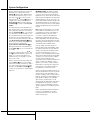
Safety Information
Important Safety Information
Verify Line Voltage Before Use
Your AVR 4500 has been designed for use with
220-240-Volt AC current. Connection to a line
voltage other than that for which it is intended
can create a safety and fire hazard and may
damage the unit.
If you have any questions about the voltage
requirements for your specific model, or about
the line voltage in your area, contact your dealer
before plugging the unit into a wall outlet.
Do Not Use Extension Cords
To avoid safety hazards, use only the power cord
attached to your unit. We do not recommend
that extension cords be used with this product.
As with all electrical devices, do not run power
cords under rugs or carpets or place heavy
objects on them. Damaged power cords should
be replaced immediately by an authorized
service depot with a cord meeting factory
specifications.
Handle the AC Power Cord Gently
When disconnecting the power cord from an AC
outlet, always pull the plug, never pull the cord.
If you do not intend to use the unit for any considerable length of time, disconnect the plug
from the AC outlet.
Do Not Open the Cabinet
There are no user-serviceable components inside
this product. Opening the cabinet may present a
shock hazard, and any modification to the
product will void your guarantee. If water or any
metal object such as a paper clip, wire or a
staple accidentally falls inside the unit,
disconnect it from the AC power source
immediately, and consult an authorized service
station.
4 SAFETY INFORMATION
Installation Location
■ To assure proper operation and to avoid the
potential for safety hazards, place the unit on
a firm and level surface. When placing the
unit on a shelf, be certain that the shelf and
any mounting hardware can support the
weight of the product.
■ Make certain that proper space is provided
both above and below the unit for ventilation.
If this product will be installed in a cabinet or
other enclosed area, make certain that there
is sufficient air movement within the cabinet.
Under some circumstances a fan may be
required.
■ Do not place the unit directly on a carpeted
surface.
■ Avoid installation in extremely hot or cold
locations, or an area that is exposed to direct
sunlight or heating equipment.
■ Avoid moist or humid locations.
■ Do not obstruct the ventilation slots on the
top of the unit, or place objects directly over
them.
Cleaning
When the unit gets dirty, wipe it with a clean,
soft, dry cloth. If necessary, wipe it with a soft
cloth dampened with mild soapy water, then a
fresh cloth with clean water. Wipe dry
immediately with a dry cloth. NEVER use
benzene, aerosol cleaners, thinner, alcohol or any
other volatile cleaning agent. Do not use
abrasive cleaners, as they may damage the finish
of metal parts. Avoid spraying insecticide near
the unit.
Moving the Unit
Before moving the unit, be certain to disconnect
any interconnection cords with other
components, and make certain that you
disconnect the unit from the AC outlet.
Unpacking
The carton and shipping materials used to
protect your new receiver during shipment were
specially designed to cushion it from shock and
vibration. We suggest that you save the carton
and packing materials for use in shipping if you
move, or should the unit ever need repair.
To minimize the size of the carton in storage,
you may wish to flatten it. This is done by
carefully slitting the tape seams on the bottom
and collapsing the carton. Other cardboard
inserts may be stored in the same manner.
Packing materials that cannot be collapsed
should be saved along with the carton in a
plastic bag.
If you do not wish to save the packaging
materials, please note that the carton and other
sections of the shipping protection are
recyclable. Please respect the environment and
discard those materials at a local recycling
center.
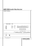
Front Panel Controls
˘
ˆ
˜
¯
ı
4500
Ù
Û
Ú
Ò
1
2
5
3
4
7
6
!
9
8
)
%
#
@
$
& (
Ô
^ * Ó
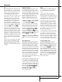
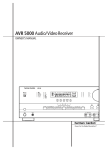
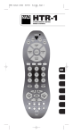
1 Main Power Switch
2 System Power Control
3 Power Indicator
4 Headphone Jack
5 Dolby Mode Selector
6 DTS Surround Mode Selector
7 Logic 7 Mode Selector /‹ Button
8 Tone Mode
9 Surround Mode Selector
) Tuning Selector
! Tuner Band Selector
@ Set Button
# Preset Station Selector
$ Stereo Mode Selector /› Button
% Input Source Selector
^ RDS Selector
& DTS Neo:6 Mode Selector
* Digital Optical 3 Input
( Input/Output Status indicator
Ó Digital Coax 3 Jack
Ô Video 4 Input Jacks
Bass Control
Ò Balance Control
Ú Treble Control
Û Digital Select Button
Ù Channel Select Button
ı Volume Control
ˆ Input Indicators
˜ Main Information Display
¯ Remote Sensor Window
˘ Surround Mode Indicators
1 Main Power Switch: Press this button to
apply power to the AVR 4500. When the switch
is pressed in, the unit is placed in a Standby
mode, as indicated by the orange LED 3 surrounding the System Power Control 2. This
button MUST be pressed in to operate the unit.
To turn the unit off completely and prevent the
use of the remote control, this switch should be
pressed until it pops out from the front panel so
that the word “OFF” may be read at the top of
the switch.
4 Headphone Jack: This jack may be used to
listen to the AVR 4500’s output through a pair of
headphones. Be certain that the headphones
have a standard 6.3 mm stereo phone plug. Note
that the main room speakers and all Preamp
Outputs b will automatically be turned off
when the headphone jack is in use.
6 DTS Surround Mode Selector: When a
DTS source is in use the AVR 4500 will select the
appropriate mode automatically and no other
mode will be available. In that case, pressing that
button will display the mode currently selected
by the AVR´s decoder. Depending on the surround
material played and the speaker setting, one of
the following modes will be selected by the unit:
• DTS-ES 6.1 DISCRETE
• DTS-ES 6.1 MATRIX
• DTS + NEO:6
• DTS 5.1
NOTE: This switch is normally left in the “ON”
position.
2 System Power Control: When the Main
Power Switch 1 is “ON,” press this button to
turn on the AVR 4500; press it again to turn the
unit off (to Standby). Note that the Power
Indicator surrounding the switch 3 will turn
green when the unit is on.
3 Power Indicator: This LED will be illuminated in orange when the unit is in the Standby
mode to signal that the unit is ready to be turned
on. When the unit is in operation, the indicator
will turn green.
5 Dolby Mode Selector: Pressing this selector
button cycles the AVR through the various Dolby
surround modes. The first press of the button
switches the surround mode to the last Dolby surround mode that was in use.
Each subsequent press selects the next mode in
the following order:
DOLBY
DIGITAL
DOLBY PRO LOGIC II MOVIE
DOLBY PRO LOGIC II
DOLBY PRO LOGIC II
EMULATION
MUSIC
DOLBY 3 STEREO
Note that DOLBY DIGITAL mode is available only
with digital input selected and the other modes
only when a Dolby Digital source is not playing.
Both DTS ES 6.1 Modes and DTS+NEO:6 will be
selected only when surround back speakers have
been configured with your system: DISCRETE
with appropriate source material, MATRIX with
6.1 Matrix recordings and DTS+NEO:6 with normal DTS 5.1 channel recordings. The DTS 5.1
mode will be selected with any DTS source, when
no surround back speakers are configured (see
also pages 24 and 32-35).
FRONT PANEL CONTROLS 5
Front Panel Controls
7 Logic 7 Mode Selector /‹ Button: This
button has two functions: In normal use, press it
to select one of the Logic 7 modes. When an
adjustment is being made using the Channel
Select Ù or Digital Select Û buttons, this
button may be pressed to scroll through the
available options.
8 Tone Mode: Pressing this button enables or
disables the Balance, Bass and Treble tone controls. When the button is pressed so that the
words TONE I N appear in the Main Information Display ˜, the settings of the Bass
and Treble Ú controls and of the Balance
control Ò will affect the output signals. When
the button is pressed so that the words TONE
OUT appear in the Main Information
Display ˜, the output signal will be “flat,”
without any balance, bass or treble alteration, no
matter how the actual Controls ÒÚ are
adjusted.
9 Surround Mode Selector: Press this button to select any of the HALL, THEATER or VMAx
surround modes. Note that depending on the
type of input, some modes are not always available. (See page 32 for more information about
surround modes.)
) Tuning Selector: Press the left side of the
button to tune lower frequency stations and the
right side of the button to tune higher frequency
stations. When a station with a strong signal is
reached, the TUNED indicator W will illuminate
in the Main Information Display ˜ (see
page 40 for more information on tuning stations).
! Tuner Band Selector: Pressing this button
will automatically switch the AVR 4500 to the
Tuner mode. Pressing it again will switch between the AM and FM frequency bands. Holding
it pressed for 3 seconds will switch between
stereo or mono receiving and automatic or manual tuning mode. When the button is pressed so
that the AUTO Indicator X lights, the tuner will
search for the next station with an acceptable signal when the Tuning Selector )Ké is
pressed. When the button is pressed so that the
AUTO Indicator X is not lit, each press of the
Tuning Selector )Ké will increase the frequency. (See page 40 for more information on
using the tuner.)
@ Set Button: When making choices during the
setup and configuration process, press this button
to enter the desired setting as shown in the Main
Information Display Û into the AVR 4500’s
memory.
# Preset Stations Selector: Press this button
to scroll up or down through the list of stations
that have been entered into the preset memory.
(See page 40 for more information on tuner programming.)
6 FRONT PANEL CONTROLS
$ Stereo Mode Selector /› Button: This
button has two functions: In normal use, pressing
this selector button cycles through the stereo
modes, and it is also used to turn off all surround
processing and place the unit in a traditional
two-channel Stereo mode. The first press selects
5-Channel Stereo or 7-Channel Stereo, depending on the selection (5.1 or 6.1/7.1) made in the
surround mode setting, see page 23, and the second selects “SURROUND OFF,” which is true
Stereo. When an adjustment is being made using
the Channel Select Ù or Digital Select Û
buttons, this button may be pressed to scroll
through the available options.
% Input Source Selector: Press this button to
change the input by scrolling through the list of
input sources.
^ RDS Select Button: Press this button to display the various messages that are part of the RDS
data system of the AVR 4500’s tuner. (See page 30
for more information on RDS).
& DTS Neo:6 Mode Selector: Pressing this
selector button cycles the AVR through the various DTS Neo:6 modes, which extract a five- or
seven-channel surround field from two-channel
program material (from PCM source or analog
input signal). The first press selects the last DTS
Neo:6 surround mode that was in use, and each
subsequent press selects the next mode in the
following order:
DTS Neo:6 MUSIC
DTS Neo:6
MOVIES
* Digital Optical 3 Input: Connect the optical
digital audio output of an audio or video product
to this jack. When the Input is not in use, be certain to keep the plastic cap installed to avoid dust
contamination that might degrade future
performance.
( Input/Output Status Indicator: This LED
indicator will normally light green to show that
the Coaxial 3 digital Ó jack is operating as an
input. When this jack has been configured for use
as an output, the indicator will turn red to show
that the jack may be used for recording. (See
page 21 for more information on configuring the
front panel jack as output, rather than input.)
Ó Digital Coax 3 Jack: This jack is normally
used for connection to the output of portable
audio devices, video game consoles or other
products that have a coax digital jack. It may also
be configured as an output jack, to feed a digital
signal to a CD-R, MiniDisc or other digital recording device. (See page 21 for information on configuring the Digital Coax 3 Jack to an output.)
Ô Video 4 Input Jacks: These audio/video
jacks may be used for temporary connection to
video games or portable audio/video products
such as camcorders and portable audio players.
Bass Control: Turn this control to modify the
low frequency output of the left/right channels by
as much as ±10dB. Set this control to a suitable
position for your taste or room acoustics.
Ò Balance Control: Turn this control to
change the relative volume for the front left/right
channels.
NOTE: For proper operation of the surround
modes this control should be at the midpoint or
“12 o’clock” position.
Ú Treble Control: Turn this control to modify the
high frequency output of the left/right channels by
as much as ±10dB. Set this control to a suitable
position for your taste or room acoustics.
Û Digital Select Button: When playing a
source that has a digital output, press this button
to select between the Optical * W and
Coaxial Ó X Digital inputs (See page
33 for more information).
Ù Channel Select Button: Press this button
to begin the process of trimming the channel output levels using an external audio source. (For
more information on output level trim adjustment, see page 35).
ı Volume Control: Turn this knob clockwise
to increase the volume, counterclockwise to
decrease the volume. If the AVR is muted, adjusting volume control will automatically release the
unit from the silenced condition.
ˆ Input indicators: A green LED will light in
front of the input that is currently being used as
the source for the AVR 4500.
˜ Main Information Display: This display
delivers messages and status indications to help
you operate the receiver. (See pages 7–8 for a
complete explanation of the Information Display.)
¯ Remote Sensor Window: The sensor
behind this window receives infrared signals from
the remote control. Aim the remote at this area
and do not block or cover it unless an external
remote sensor is installed.
˘ Surround Mode Indicators: A green LED
will light in front of the surround mode that is
currently in use.
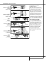
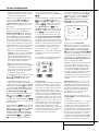
Front Panel Information Display
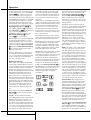
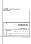
A
B
C
D
E
F
G
H
I
J
K
Bitstream Indicators
Optical Source Indicators
Sample Rate Indicators
DTS Mode Indicator
Dolby Digital Indicator
Coaxial Source Indicators
Dolby Pro Logic II Indicator
Analog Input Indicator
Dolby 3 Stereo Indicator
Logic 7 Mode Indicators
5 Channel/7 Channel Stereo Indicators
A Bitstream™ Indicators: When the input is a
digital source, one of these indicators will light to
display the specific type of signal in use.
B Optical Source Indicators: These indicators light to show when a Optical Digital Input
has been selected.
C Sample Rate Indicators: One of these
indicators will light when 96kHz or 192kHz
source material is in use.
D DTS Mode Indicator: This indicator illuminates when the DTS mode is selected
E Dolby Digital Indicator: This indicator
illuminates when the Dolby Digital mode is
selected.
F Coaxial Source Indicators: These indicators light to show when a Coaxial Digital Input
has been selected.
G Dolby Pro Logic II Indicator: This indicator lights when any Dolby Pro Logic II mode has
been selected.
NOTE: It is possible to see the Dolby Pro Logic II
indicator lit simultaneously with the Dolby Digital
indicator, even though the Dolby Digital surround
mode has been selected. This is due to the specifications for Dolby Digital processing, which
require that the Dolby Pro Logic II mode be
applied when a 2-channel Dolby Digital signal
(2.0 recording) with Pro Logic information (Pro
Logic flag on) is detected. For more information
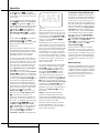
L
M
N
O
P
Q
R
S
T
U
V
Hall Mode Indicator
Theater Mode Indicator
VMAx Mode Indicator
Multiroom Indicator
OSD Indicator
Speaker/Channel Input Indicators
Preset Number/Sleep Timer
Preset Indicator
Sleep Indicator
Memory Indicator
Stereo Indicator
see page 34. If you desire 5.1-channel audio,
check the audio settings in the menus for your
DVD disc to make sure that a 5.1-channel Dolby
Digital soundtrack has been selected.
H Analog Input Indicator: This indicator
lights when an analog input source has been
selected.
I Dolby 3 Stereo Indicator: This indicator
lights when the Dolby 3 Stereo Mode has been
selected.
J Logic 7 Mode Indicators: These indicators
light to indicate that one of the Logic 7 modes is
in use. Along with the main Logic 7 indicator,
either 5.1 or 7.1 will light to indicate the selected
speaker configuration. One of the three letters to
the far right of this segment will light to show
which version of Logic 7 processing is in use: C
for the Cinema mode, M for the Music mode and
E for the Enhanced mode used with two-channel
sources. (See page 29 for a description of the
Logic 7 modes.)
K 5-Channel/7-Channel Stereo Indicators:
These indicators light to show if the 5-Channel or
7-Channel Stereo mode has been selected. Only
the indicator STEREO will light when
"Surround Off" has been selected. Then all
Surround Modes are turned off and the unit will
play in pure stereo mode.
W Tuned Indicator
X Auto Indicator
Y Main Information Display
Z Mute Indicator
AA Traffic Indicator
AB Radiotext Indicator
AC Clock Time Indicator
AD Program Type Indicator
AE RDS Indicator
L Hall Mode Indicators: These indicators
light when one of the Hall modes has been
selected.
M Theater Mode Indicator: This indicator illuminates to show that the Theater mode is in use.
N VMAx Mode Indicators: One of these indicators lights when the VMAx mode is in use.
V M A x F appears when the Far Field VMAx
mode is selected; V M A x N appears when the
Near Field VMAx mode is selected. (See page 29
for a description of the VMAx modes.)
O Multiroom Indicator: This indicator lights
when the multiroom system is active. Note that it
will remain lit when the multiroom system is in
use even though the main room system is in the
Standby mode and all other indicators are dark.
(See page 39 for more information on the
Multiroom system.)
P OSD Indicator: When the OSD system is in
use, this indicator lights to remind you that the
other indicators in this display do not function
when the On Screen Display is being used.
FRONT PANEL INFORMATION DISPLAY 7
Front Panel Information Display
Q Speaker/Channel Input Indicators: These
indicators are multipurpose, indicating either the
speaker type selected for each channel or the
incoming data-signal configuration. The left, center, right, right surround, left surround, right back
surround and left back surround speaker indicators are composed of three boxes, while the subwoofer is a single box. The center box lights when
a “Small” speaker is selected, and the two outer
boxes light when “Large” speakers are selected.
When none of the boxes are lit for the center, surround or subwoofer channels, no speaker has
been selected for that position. (See page 21 for
more information on configuring speakers.) The
letters inside each of the center boxes display
active input channels. For standard analog inputs,
only the L and R will light, indicating a stereo
input. When a digital source is playing, the indicators will light to display the channels begin
received at the digital input. When the letters
flash, the digital input has been interrupted. (See
pages 23 and 34 for more information on the
Channel Indicators).
R Preset Number/Sleep Timer: When the
tuner is in use, these numbers indicate the specific preset memory location in use. (See page 40
for more information on preset stations.) When
the Sleep function is in use, these numbers show
how many minutes remain before the unit goes
into the Standby mode.
S Preset Indicator: This indicator lights when
the tuner is in use to show that the Preset
Number/Sleep Timer R is showing the station’s preset memory number. (See page 40 for
more information on tuner presets.)
T Sleep Indicator: This indicator lights when
the Sleep function is in use. The numbers in the
Preset Number/Sleep Timer R indicators
will show the minutes remaining before the
AVR 4500 goes into the Standby mode.
(See page 31 for more information on the Sleep
function.)
8 FRONT PANEL INFORMATION DISPLAY
U Memory Indicator: This indicator flashes
when entering presets and other information
into the tuner’s memory.
V Stereo Indicator: This indicator illuminates
when an FM station is being tuned in stereo.
W Tuned Indicator: This indicator illuminates
when a station is being received with sufficient signal strength to provide acceptable listening quality.
X Auto Indicator: This indicator illuminates
when the tuner’s Auto mode is in use.
Y Main Information Display: This display
shows messages relating to the status, input
source, surround mode, tuner, volume level or
other aspects of the AVR 4500’s operation.
Z Mute Indicator: This indicator illuminates
to remind you that the AVR 4500’s output has
been silenced by pressing the Mute button
˚. Press the Mute button again to return
to the previously selected output level.
AA TA Traffic Announcement Indicator:
This indicator illuminates if the RDS station
tuned somtimes transmits traffic information
(see page 41 for more information on RDS).
AB RT Text Indicator: This indicator illuminates when the RDS station tuned is transmitting radiotext (RT) data.
AC Clock Time Indicator: This indicator illuminates when the RDS station tuned is transmitting the CT (clock time) code, indicating the current time of day.
AD PTY Indicator: This indicator illuminates
when the RDS station tuned is transmitting program type data, or during a PTY search.
AE RDS Indicator: This indicator illuminates
when the station tuned is transmitting RDS data.
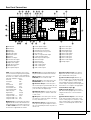
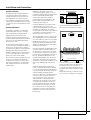
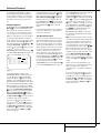
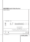
Rear Panel Connections
a Y W U
XV T
b Z
S QO M
RP N
I
K
L
J
230 V/50Hz
0
AC OUTLETS
~230V/50Hz
1
UNSWITCHED / 100W MAX
H
SWITCHED / 50W MAX
2
3
0
1
2
3
4
5
6
7
8
9
A
B
C
D
57
46
8
9 B
A C
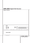
AM Antenna
FM Antenna
Tape Inputs
Tape Outputs
Subwoofer Output
DVD Audio Inputs
CD Inputs
Multiroom Outputs
6-Channel Direct Inputs
8-Channel Direct Inputs
Digital Audio Outputs
Video Monitor Outputs
DVD Video Inputs
Front Speaker Outputs
NOTE: To assist in making the correct connections for multichannel input/output and speaker
connections, all connection jacks and terminals
have been color coded in conformance with the
latest CEA standards as follows:
Front Left:
White
Front Right:
Red
Center:
Green
Surround Left:
Blue
Surround Right:
Gray
Surround Back Left:
Brown
Surround Back Right:
Tan
Subwoofer (LFE):
Purple
Digital Audio:
Orange
Composite Video:
Yellow
Component Video “Y”: Green
Component Video “Pr”: Red
Component Video “Pb”: Blue
0 AM Antenna: Connect the AM loop antenna
supplied with the receiver to these terminals. If an
external AM antenna is used, make connections to
the AM and GND terminals in accordance with
the instructions supplied with the antenna.
E
F
G
H
I
J
K
L
M
N
O
P
Q
R
D
E
Center Speaker Outputs
Surround Speaker Outputs
Switched AC Accessory Outlet
Unswitched AC Accessory Outlet
AC Power Cord
Video 2 Component Video Inputs
Component Video Outputs
DVD Component Video Inputs
Remote IR Output
Remote IR Input
Multiroom IR Input
Video 1 Video Outputs
Video 1 Video Inputs
Video 2 Video Outputs
1 FM Antenna: Connect the supplied indoor or
an optional external FM antenna to this terminal.
2 Tape Inputs: Connect these jacks to the
PLAY/OUT jacks of an audio recorder.
3 Tape Outputs: Connect these jacks to the
RECORD/INPUT jacks of an audio recorder.
4 Subwoofer Output: Connect this jack to
the line-level input of a powered subwoofer. If an
external subwoofer amplifier is used, connect this
jack to the subwoofer amplifier input.
5 DVD Audio Inputs: Connect these jacks to
the analog audio jacks on a DVD or other audio
or video source.
6 CD Inputs: Connect these jacks to the analog output of a compact disc player or CD changer or any other audio source.
7 Multiroom Outputs: Connect these jacks
to an optional audio power amplifier to listen to
the source selected by the multiroom system in a
remote room.
F
S
T
U
V
W
X
Y
Z
a
b
G
Video 3 Video Inputs
Video 2 Video Inputs
Optical Digital Inputs
Coaxial Digital Inputs
Video 2 Audio Outputs
Video 2 Audio Inputs
Video 3 Audio Inputs
Video 1 Audio Inputs
Video 1 Audio Outputs
Preamp Outputs
8 6-Channel Direct Inputs: If an external
digital audio decoder is used, connect the outputs of that decoder to these jacks.
9 8-Channel Direct Inputs: When an optional, external processor or playback device with
6.1 or 7. 1 audio capability is in use, connect the
Surround Back Left and Surround Back Right
channel outputs of the player to these input jacks
and all other 6.1/7.1 outputs to the appropriate
6-Channel Direct Inputs 8.
A Digital Audio Outputs: Connect these
jacks to the matching digital input connector on
a digital recorder such as a CD-R or MiniDisc
recorder.
B Video Monitor Outputs: Connect this jack
to the composite and/or S-Video input of a TV
monitor or video projector to view the on-screen
menus and the output of any standard Video or
S-Video source selected by the receiver’s video
switcher.
REAR PANEL CONNECTIONS 9
Rear Panel Connections
C DVD Video Inputs: Connect these jacks to
the composite or S-Video output jacks on a DVD
player or other video source.
D Front Speaker Outputs: Connect these
outputs to the matching + or – terminals on
your left and right speakers. In conformance with
the new CEA color code specification, the White
terminal is the positive, or "+" terminal that
should be connected to the red (+) terminal on
Front Left speaker with the older color coding,
while the Red terminal is the positive, or "+"
terminal that should be connected to the red (+)
terminal on Front Right speaker. Connect the
black (–) terminals on the AVR 4500 to the black
(–) terminals on the speakers. See page 15 for
more information on speaker polarity.
E Center Speaker Outputs: Connect these
outputs to the matching + and – terminals on
your center channel speaker. In conformance
with the new CEA color code specification, the
Green Terminal is the positive, or "+" terminal
that should be connected to the red (+) terminal
on speakers with the older color coding. Connect
the black (–) terminal on the AVR to the black
negative (–) terminal on your speaker. (See page
15 for more information on speaker polarity.)
F Surround Speaker Outputs: Connect
these outputs to the matching + and – terminals
on your surround channel speakers. In conformance with the new CEA color code specification, the Blue terminal is the positive, or "+"
terminal that should be connected to the red (+)
terminal on the Surround Left speaker with older
color coding, while the Gray terminal should be
connected to the red (+) terminal on the
Surround Right speaker with the older color coding. Connect the black (–) terminal on the AVR
to the matching black negative (–) terminals for
each surround speaker. (See page 15 for more
information on speaker polarity.)
G Switched AC Accessory Outlet: This outlet may be used to power any device that you
wish to have turn on when the AVR 4500 is
turned on with the System Power Control
switch 2.
H Unswitched AC Accessory Outlet: This
outlet may be used to power any AC device. The
power will remain on at this outlet regardless of
whether the AVR 4500 is on or off (in Standby),
provided that the Main Power switch 1 is on.
Note: The total power consumption of all
devices connected to the accessory outlets
should not exceed 100 watts from the
Unswitched Outlet H and 50 W from the
Switched Outlet G.
10 REAR PANEL CONNECTIONS
I AC Power Cord: Connect the AC plug to an
unswitched AC wall output.
J Video 2 Component Video Inputs:
Connect the Y/Pr/Pb component video outputs of
an HDTV Set-top convertor, satellite receiver, or
other video source device with component video
outputs to these jacks.
K Monitor Component Video Outputs:
Connect these outputs to the component video
inputs of a video projector or monitor. When a
source connected to one of the two
Component Video Inputs JL is selected
the signal will be sent to these jacks.
L DVD Component Video Inputs: Connect
the Y/Pr/Pb component video outputs of a DVD
player to these jacks.
Note: All component inputs/outputs can be
used for RGB signals too, in the same way as
described for the Y/Pr/Pb signals, then connected
to the jacks with the corresponding color.
RGB connection is not possible if the source outputs a separate sync signal (see page 16).
M Remote IR Output: This connection permits
the IR sensor in the receiver to serve other
remote controlled devices. Connect this jack to
the “IR IN” jack on Harman Kardon or other
compatible equipment.
N Remote IR Input: If the AVR 4500’s frontpanel IR sensor is blocked due to cabinet doors
or other obstructions, an external IR sensor
may be used. Connect the output of the sensor
to this jack.
O Multiroom IR Input: Connect the output of
an IR sensor in a remote room to this jack to
operate the AVR 4500’s multiroom control system.
P Video 1 Video Outputs: Connect these
jacks to the RECORD/INPUT composite or
S-Video jack on a VCR.
Q Video 1 Video Inputs: Connect these jacks
to the PLAY/OUT composite or S-Video jacks on
a VCR or other video source.
R Video 2 Video Outputs: Connect these
jacks to the RECORD/INPUT composite or
S-Video jacks on a second VCR.
S Video 3 Video Inputs: Connect these jacks
to the PLAY/OUT composite or S-Video jacks on
any video source.
T Video 2 Video Inputs: Connect these jacks
to the PLAY/OUT composite or S-Video jacks on
a second VCR or other video source.
U Optical Digital Inputs: Connect the optical digital output from a DVD player, HDTV
receiver, the S/PDIF output of a compatible computer sound card playing MP3 files or streams,
LD player, MD player or CD player to these jacks.
The signal may be either a Dolby Digital signal, a
DTS signal, a 2 channel MPEG 1 signal, an MP3
data stream or a standard PCM digital source.
V Coaxial Digital Inputs: Connect the coax
digital output from a DVD player, HDTV receiver,
the S/PDIF output of a compatible computer
sound card playing MP3 files or streams, LD
player, MD player or CD player to these jacks.
The signal may be either a Dolby Digital signal,
DTS signal, a 2 channel MPEG 1 signal, an MP3
data stream or a standard PCM digital source.
Do not connect the RF digital output of an LD
player to these jacks.
W Video 2 Audio Outputs: Connect these
jacks to the RECORD/INPUT audio jacks on a
VCR or any Audio recorder.
X Video 2 Audio Inputs: Connect these jacks
to the PLAY/OUT audio jacks on a second VCR
or other audio or video source.
Y Video 3 Audio Inputs: Connect these jacks
to the PLAY/OUT audio jacks on any audio or
video source.
Z Video 1 Audio Inputs: Connect these jacks
to the PLAY/OUT audio jacks on a VCR or other
audio or video source.
a Video 1 Audio Outputs: Connect these
jacks to the RECORD/INPUT audio jacks on
a VCR or any other Audio recorder.
b Preamp Outputs: These jacks may be connected to an external power amplifier.
Note: Either the Video or S-Video output of any
S-Video source must be connected to the
AVR 4500, not both in parallel, otherwise the
video may be disturbed or its performance be
adversely effected.
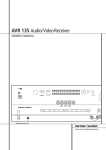
Main Remote Control Functions
0
1
2
3
4
5
6
7
8
9
A
B
C
D
E
F
G
H
I
J
K
L
M
N
O
P
Q
!
"
#
$
%
&
'
(
)
*
+
Power On Button
IR Transmitter Window
Program/SPL Indicator
Power Off Button
Input Selectors
AVR Selector
AM/FM Tuner Select
6-Channel/8-Channel Direct Input
Test Button
Sleep Button
Surround Mode Selector
Night Mode
Channel Select Button
⁄ / ¤ Buttons
‹ Button
Set Button
Digital Select
Numeric Keys
Tuner Mode
Direct Button
Tuning Up/Down
OSD Button
Dolby Mode Select Button
DTS Digital Mode Selector
Logic 7 Mode Select Button
Transport Controls
Skip Up/Down Buttons
Stereo Mode Select Button
DTS Neo:6 Mode Select
Macro Buttons
RDS Selector Button
Preset Up/Down
Clear Button
Memory Button
Delay/Prev. Ch.
› Button
Speaker Select
Multiroom
Volume Up/Down
SPL Indicator Select
Learn Button
Mute
EzSet Sensor Microphone
NOTE: The function names shown here are each
button’s feature when used with the AVR 4500.
Most buttons have additional functions when
used with other devices. See page 48-49 for a
list of these functions.
MAIN REMOTE CONTROL FUNCTIONS 11
Main Remote Control Functions
IMPORTANT NOTE: The AVR4500’s remote may
be programmed to control up to seven devices,
including the AVR 4500. Before using the remote,
it is important to remember to press the Input
Selector button 4 that corresponds to the unit
you wish to operate. In addition, the AVR 4500’s
remote is shipped from the factory to operate the
AVR 4500 and most Harman Kardon CD or DVD
players and cassette decks. The remote is also
capable of operating a wide variety of other products using the control codes that are part of the
remote or by learning commands from other
remotes. Before using the remote with other products, follow the instructions on pages 42-45 to
program the proper codes for the products in your
system.
It is also important to remember that many of the
buttons on the remote take on different functions,
depending on the product selected using the
Input Selector Button 4. The descriptions
shown here primarily detail the functions of the
remote when it is used to operate the AVR 4500.
(See page 45 for information about alternate
functions for the remote’s buttons.)
0 Power Off Button: Press this button to
place the AVR 4500 or a selected device unit in the
Standby mode. Note that when the AVR 4500 is
switched off this will turn off the main room functions, but if the Multiroom system is activated, it
will continue to function.
1 IR Transmitter Window: Point this window
towards the AVR 4500 when pressing buttons on
the remote to make certain that infrared commands
are properly received.
2 Program/SPL Indicator: This three-color
indicator is used to guide you through the process
of programming the remote or learning commands
from a remote into the AVR 4500’s remote code
memory and it is also used as a level indicator
when using the remote’s EzSet capabilities. (See
page 26 for more information on setting output
levels, and see page 42 for information on programming the remote.)
3 Power On Button: Press this button to turn
on the power to a device selected by pressing one
of the Input Selectors 4 (except Tape).
4 Input Selectors: Pressing one of these buttons will perform three actions at the same time.
First, if the AVR is not turned on, this will power
up the unit. Next, it will select the source shown
on the button as the input to the AVR. Finally, it
will change the remote control so that it controls
the device selected. After pressing one of these
buttons you must press the
AVR Selector button 5 again to operate the
AVR’s functions with the remote.
12 MAIN REMOTE CONTROL FUNCTIONS
5 AVR Selector: Pressing this button will
switch the remote so that it will operate the AVR’s
functions. If the AVR is in the Standby mode, it will
also turn the AVR on.
6 AM/FM Tuner Select: Press this button to
select the AVR’s tuner as the listening choice.
Pressing this button when the tuner is in use will
select between the AM and FM bands.
7 6-Channel/8 Channel Direct Input: Press
this button to select the device connected to the
6-Channel Direct Inputs 8 or the
8-Channel Direct Inputs 89 (the input available will depend on the selection 5.1 or 6.1/7.1
made in the surround mode setting, see page 23
for more information).
8 Test Tone: Press this button to begin the
sequence used to calibrate the AVR 4500’s output
levels. (See page 26 for more information on
calibrating the AVR 4500.)
9 Sleep Button: Press this button to place the
unit in the Sleep mode. After the time shown in
the display, the AVR 4500 will automatically go
into the Standby mode. Each press of the button
changes the time until turn-off in the following
order:
90
min
80
min
70
min
60
min
50
min
40
min
30
min
20
min
10
min
OFF
Hold the button pressed for two seconds to turn
off the Sleep mode setting.
Note that this button is also used to change
channels on your TV, VCR and Sat receiver when
the appropriate source is selected, using the
device Input Selectors 4.
A Surround Mode Selector: Press this button to select any of the HALL, THEATER or VMAx
surround modes. Note that depending on the type
of input, some modes are not always available.
(See page 29 for more information about surround modes.) Note that this button is also used
to tune channels on your TV, VCR and Sat receiver
when the appropriate source is selected using the
device Input Selector 4.
B Night Mode: Press this button to activate
the Night mode. This mode is available only with
Dolby Digital encoded sources, and it preserves
dialog (center channel) intelligibilty at low volume
levels (See page 25 for more information).
C Channel Select Button: This button is
used to start the process of setting the AVR
4500’s output levels with an external source.
Once this button is pressed, use the ⁄/¤ buttons
D to select the channel being adjusted, then
press the Set button F, followed by the ⁄/¤
buttons D again, to change the level setting.
(See page 35 for more information.)
D ⁄/¤ Buttons:These multipurpose buttons
are used to change or scroll through items in the
on-screen menus or on the front panel or to make
configuration settings such as digital inputs or
delay timing. When changing a setting, first press
the button for the function or setting to be
changed (e.g., press the Digital Select Button
G to change a digital input) and then press one
of these buttons to scroll through the list of
options or to increase or decrease a setting. The
sections in this manual describing the individual
features and functions contain specific information on using these buttons for each application.
When the AVR 4500 remote is being programmed
for the codes of another device, these buttons are
also used in the “Auto Search” process (See page
42 for more information on programming the
remote.)
E ‹ Button: This button is used to change the
menu selection or setting during some of the
setup procedures for the AVR 4500.
F Set Button: This button is used to enter settings into the AVR 4500’s memory. It is also used
in the setup procedures for delay time, speaker
configuration and channel output level adjustment.
G Digital Select: Press this button to assign
one of the digital inputs UV*Ó to a source.
(See page 33 for more information on using digital inputs.)
H Numeric Keys: These buttons serve as a
ten-button numeric keypad to enter tuner preset
positions. They are also used to select channel
numbers when TV, VCR or Sat receiver has been
selected on the remote, or to select track numbers
on a CD, DVD or LD player, depending on how the
remote has been programmed.
I Tuner Mode: Press this button when the
tuner is in use to select between automatic tuning and manual tuning. When the button is
pressed so that the AUTO indicator X goes out,
pressing the Tuning buttons K)≠ will
move the frequency up or down in single-step
increments. When the FM band is in use and the
AUTO indicator X is on, pressing this button will
change to monaural reception making even weak
stations audible or improving the audio performance with noisy stereo stations. (See page 40 for
more information.)
J Direct Button: Press this button when the
tuner is in use to start the sequence for direct
entry of a station’s frequency. After pressing the
button simply press the proper Numeric Keys
H to select a station (See page 40 for more
information on the tuner).
Main Remote Control Functions
K Tuning Up/Down: When the tuner is in use,
these buttons will tune up or down through the
selected frequency band. If the Tuner Mode button I has been pressed or the Band button
@ on the front panel was held pressed so that
the AUTO indicator X is illuminated, pressing
either of the buttons will cause the tuner to seek
the next station with acceptable signal strength
for quality reception. When the AUTO indicator
X is NOT illuminated, pressing these buttons will
tune stations in single-step increments. (See page
40 for more information.)
L OSD Button: Press this button to activate
the On Screen Display (OSD) system used to set up
or adjust the AVR 4500’s parameters.
M Dolby Mode Selector: This button is used
to select one of the available Dolby Surround processing modes. Each press of this button will
select one of the Dolby Pro Logic II modes, Dolby 3
Stereo or Dolby Digital. Note that the Dolby
Digital mode is only available with a digital input
selected and the other modes only as long as a
Dolby Digital source is not playing (except Pro
Logic II with Dolby Digital 2.0 recordings, see
Note on page 7). See page 29 for the available
Dolby surround mode options.
N DTS Digital Mode Selector: When a DTS
source is in use the AVR 4500 will select the
appropriate mode automatically and no other
mode will be available. Pressing this button will
display the mode currently selected by the AVR´s
decoder, depending on the surround material
played and the speaker setting (see item 6,
page 5). When a DTS source is not in use, this button has no function. (See page 24, 29 for the
available DTS options.)
O Logic 7 Selector: Press this button to select
one of the available Logic 7 surround modes. (See
page 29 for the available Logic 7 options.)
P Transport Control Buttons: These buttons
do not have any functions for the AVR 4500, but
they may be programmed for the forward/reverse
play operation of a wide variety of CD or DVD
players, and audio or video- cassette recorders.
(See page 42 for more information on programming the remote.)
Q Skip Up/Down Buttons: These buttons do
not have a direct function with the AVR 4500, but
when used with a compatibly programmed CD or
DVD player/changer they will change the tracks
on the disc currently being played.
Stereo Mode Select Button: Pressing this
selector button cycles through the stereo modes,
and it is also used to turn off all surround processing and place the unit in a traditional twochannel Stereo mode. The first press selects 5Channel Stereo or 7-Channel Stereo, depending
on the selection (5.1 or 6.1/7.1) made in the surround mode setting, see page 23, and the second
selects “SURROUND OFF,” which is true Stereo.
DTS Neo:6 Mode Selector: Pressing this
selector button cycles the AVR through the various DTS Neo:6 modes, which extract a five- or
seven-channel surround field from two-channel
program material (from PCM source or analog
input signal). The first press selects the last DTS
Neo:6 surround mode that was in use, and each
subsequent press selects the next mode in the following order:
DTS Neo:6 MUSIC
DTS Neo:6
MOVIES
Macro Buttons: Press these buttons to
store or recall a “Macro”, which is a pre-programmed sequence of commands stored in the
remote. (See page 44 for more information on
storing and recalling macros.)
RDS Select Button: Press this button to display the various messages that are part of the RDS
data system of the AVR 4500’s tuner. (See page 41
for more information on RDS).
! Preset Up/Down: When the tuner is in use,
press these buttons to scroll through the stations
programmed into the AVR 4500’s memory. When
CD or DVD is selected using the Input Selector
button 4, these buttons may function as Slow
Fwd/Rev (DVD) or ”+10” (CD, CDR).
" Clear Button: Press this button to clear incorrect entries when using the remote to
directly enter a radio station’s frequency.
# Memory Button: Press this button to enter a
radio station into the AVR 4500’s preset memory.
After pressing the button the MEMORY indicator
U will flash; you then have five seconds to enter
a preset memory location using the Numeric
Keys H. (See page 40 for more information.)
$ Delay/Prev Ch.: Press this button to begin
the process for setting the delay times used by
the AVR 4500 when processing surround sound.
After pressing this button, the delay times are
entered by pressing the Set button F and then
using the ⁄/¤ buttons D to change the setting. Press the Set button again to complete the
process. (See page 25 for more information.)
& Speaker Select: Press this button to begin
the process of configuring the AVR 4500’s Bass
Management System for use with the type of
speakers used in your system. Once the button
has been pressed, use the ⁄/¤ buttons D to
select the channel you wish to set up.
Press the Set Button F and then select the
speaker type (Large, Small or None) appropriate
with the speaker in use. (See page 21 for more
information.)
' Multi-Room: Press this button to activate
the Multiroom system or to begin the process of
changing the input or volume level for the second
zone. (See page 39 for more information on the
Multiroom system.)
( Volume Up/Down: Press these buttons to
raise or lower the system volume.
) SPL Indicator Select: This button activates
the AVR 4500’s EzSet function to quickly and
accurately calibrate the AVR 4500’s output levels.
During this sequence, EzSet will automatically
adjust the output levels for all channels until they
are equal, as shown by the Program Indicator
2 lighting green for each channel. (See page
26 for more information on EzSet.)
* Learn Button: Press this button to begin the
process of “learning” the codes from another
product’s remote into the AVR 4500’s remote. (See
page 43 for more information on using the
remote’s learning function.)
Mute: Press this button to momentarily
silence the AVR 4500 or TV set being controlled,
depending on which device has been selected.
When the AVR 4500 remote is being programmed
to operate another device, this button is pressed
with the Input Selector button 4 to begin the
programming process. (See page 42 for more
information on programming the remote.)
+ EzSet Sensor Microphone: The sensor
microphone for the EzSet microphone is behind
these slots. When using the remote to calibrate
speaker output levels using EzSet, be sure that
you do not hold the remote in a way that covers
these slots. (See page 26 for more information on
using EzSet).
NOTE: With the press of any remote button the
Input Selector button 45 associated with
the botton pressed will briefly flash red to confirm
the transmission of the command, as long as
there is a function for that button with the device
selected (see function list on pages 48, 49).
% › Button: Press this button to change a setting or selection when configuring many of the
AVR’s settings.
MAIN REMOTE CONTROL FUNCTIONS 13
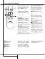
Zone II Remote Control Functions
POWER
A
MUTE
K
OFF
AVR
VID1
VID2
AM//FM
VID3
VID4
DVD
CD
TAPE
DN
TUNING
UP
DN
PRESET
UP
The Zone II remote may be used in either the
same room where the AVR 4500 is located, or it
may be used in a separate room with an optional infrared sensor that is connected to the
AVR 4500’s Multi IR input jack O.
B
C
D
E
F
G
å Power Off: When used in the room where
the AVR 4500 is located, press this button to
place the unit in Standby. When it is used in a
remote room with a sensor that is connected to
the Multi IR jack O, this button turns the
Multi-Room system off.
H
DISC SKIP
J
DISC SKIP
I
VOLUME
∫ AVR Selector: Press this button to turn on
the AVR. The input in use when the unit was last
on will be selected.
ç AM/FM Tuner Select: Press this button to
select the Tuner as the input to the Multiroom
system. Press it again to change between the
AM and FM bands.
∂ Input Selectors: When the AVR is off,
press one of these buttons to turn the unit on
and to select a specific input. When the unit is
already in use, pressing one of these buttons will
change the input.
≠ Tuning Up/Down – Fast Play: These buttons may be used to change the frequency of
the tuner. These buttons may also control the
Fast Play or Fast Reverse functions of compatible
Harman Kardon CD, DVD or cassette decks in
the same room, or from a remote room when an
IR link is connected to the AVR 4500.
ƒ Record/Pause: Press this button to activate the Record or Pause function on compatible
Harman Kardon CD, DVD or Cassette Deck products.
å
∫
ç
∂
≠
ƒ
©
˙
î
∆
˚
Power Off
AVR Selector
AM/FM Tuner Select
Input Selectors
Tuning Up/Down – Fast Play
Record/Pause
Preset/Track Skip
Disc Skip
Volume Up/Down
Play Forward/Reverse/Stop
Mute
14 ZONE II REMOTE CONTROL FUNCTIONS
NOTE: The Zone II remote may be used in either
the same room where the AVR 4500 is located,
or it may be used in a separate room with an
optional infrared sensor that is connected to the
AVR 4500’s Multi IR input jack b. When it is
used in the same room as the AVR 4500, it will
control the functions of the AVR 4500 or any
compatible Harman Kardon products in that
room. When it is used in a separate room via a
sensor connected to the Multi IR Jack b, the
buttons for power, input source, volume and
© Preset Up/Down – Track Skip: When the
AVR’s tuner is selected as the input source, these
buttons will move up or down through the list of
stations that have been stored in the preset
memory. When a CD or DVD player is selected,
these buttons activate the forward or reverse
track or chapter skip functions.
˙ Disc Skip: Press this button to change
discs on compatible Harman Kardon CD or DVD
changers.
î Volume Up/Down: When used in the
room where the AVR 4500 is located, press this
button to raise or lower the volume in that
room. When it is used in a remote room with a
sensor that is connected to the Multi IR Jack
O, this button will raise or lower the volume in
the remote room.
∆ Play Forward/Reverse/Stop: Press these
buttons to control compatible Harman Kardon
CD, DVD or cassette players.
˚ Mute: When used in the room where the
AVR 4500 is located, press this button to temporarily silence the unit. When it is used in a
remote room with a sensor that is connected to
the Multi IR Jack O, this button will temporarily silence the feed to the remote room only.
Press the button again to return to the previous
volume level.
Important Note: No matter in which room the
Zone II remote is used, as with the main remote
it is important to remember to press the Input
Selector button ∂ that corresponds to the
unit you wish to operate befor you change the
device to be controlled.
mute will control the source and volume for the
second zone, as connected to the Multi Out
Jacks ‚. (See page 39 for complete information
on using the Multiroom system.)
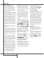
Installation and Connections
After unpacking the unit, and placing it on a solid
surface capable of supporting its weight, you will
need to make the connections to your audio and
video equipment.
Audio Equipment Connections
We recommend that you use high-quality interconnect cables when making connections to
source equipment and recorders to preserve the
integrity of the signals.
When making connections to audio source
equipment or speakers it is always a good practice to unplug the unit from the AC wall outlet.
This prevents any possibility of accidentally sending audio or transient signals to the speakers
that may damage them.
1. Connect the analog output of a CD player to
the CD inputs 6.
NOTE: When the CD player has both fixed and
variable audio outputs it is best to use the fixed
output unless you find that the input to the
receiver is so low that the sound is noisy, or so
high that the signal is distorted.
2. Connect the analog Play/Out jacks of a cassette deck, MD, CD-R or other audio recorder to
the Tape Input jacks 2. Connect the analog
Record/In jacks on the recorder to the Tape
Output jacks 3 on the AVR 4500.
3. Connect the digital output of any digital
sources such as a CD or DVD changer or player,
advanced video game, a digital satellite receiver,
HDTV tuner or digital cable set-top box or the
output of a compatible computer sound card to
the Optical and Coaxial Digital Inputs
U V *Ó.
4. Connect the Coaxial or Optical Digital
Outputs A on the rear panel of the AVR to the
matching digital input connections on a CD-R or
MiniDisc recorder.
5. Assemble the AM Loop Antenna supplied with
the unit as shown below. Connect it to the AM
and GND screw terminals 0.
6. Connect the supplied FM antenna to the FM
(75 ohm) connection 1. The FM antenna may
be an external roof antenna, an inside powered
or wire lead antenna or a connection from a
cable system. Note that if the antenna or connection uses 300-ohm twin-lead cable, you should
use a 300-ohm-to-75-ohm adapter to make the
connection.
7. Connect the front, center and surround speaker outputs DEF to the respective speakers.
To assure that all the audio signals are carried to
your speakers without loss of clarity or resolution, we suggest that you use high-quality speaker cable. Many brands of cable are available and
the choice of cable may be influenced by the distance between your speakers and the receiver,
the type of speakers you use, personal preferences and other factors. Your dealer or installer is
a valuable resource to consult in selecting the
proper cable.
Regardless of the brand of cable selected, we recommend that you use a cable constructed of fine,
multistrand copper with an area greater than 2
mm2.
Cable with an area of 1.5 mm2 may be used for
short runs of less than 4 m. We do not recommend that you use cables with an area less than
1mm2 due to the power loss and degradation in
performance that will occur.
Cables that are run inside walls should have the
appropriate markings to indicate listing with any
appropriate testing agency standards. Questions
about running cables inside walls should be
referred to your installer or a licensed electrician
who is familiar with the applicable local building
codes in your area.
When connecting wires to the speakers, be certain to observe proper polarity. Note that the
positive (+) terminal of each speaker connection
now carries a specific color code as noted on
page 9. However, most speakers will still use a
red terminal for the postive (+) connection.
Connect the “negative” or “black” wire to the
same terminal on both the receiver and the
speaker.
NOTE: While most speaker manufacturers
adhere to an industry convention of using black
terminals for negative and red ones for positive,
some manufacturers may vary from this configuration. To assure proper phase and optimal performance, consult the identification plate on your
speaker or the speaker’s manual to verify polarity.
If you do not know the polarity of your speaker,
ask your dealer for advice before proceeding, or
consult the speaker’s manufacturer.
We also recommend that the length of cable
used to connect speaker pairs be identical. For
example, use the same length piece of cable to
connect the front-left and front-right or surround-left and surround-right speakers, even if
the speakers are a different distance from the
AVR 4500.
passive subwoofer is used, the connection first
goes to a power amplifier, which will be connected to one or more subwoofer speakers. If you are
using a powered subwoofer that does not have
line-level input connections, follow the instructions furnished with the speaker for connection
information.
9. If an external multi-channel audio source with
5.1 outputs such as an external digital processor/decoder, DVD-Audio or SACD player is used,
connect the outputs of that device to the 6Channel Direct Inputs 8.
10. If an external multi-channel audio source
with 7.1 outputs such as an external digital
processor/decoder, DVD-Audio or SACD player is
used, first connect the outputs of that device to
the 6 Channel Direct Inputs as noted above, and
then connect the Surround Back Left and
Surround Back Right output channels of the
source device to the 8-Channel Direct Inputs
9.
11. If a 7.1 channel source device is connected
as noted in the item above, you must use an
optional audio power stereo amplifier for the
Surround Back channels. Connect the SBL and
SBR Preamp Outputs b to the inputs of the
amplifier feeding those channels' speakers.
Video Equipment Connections
Video equipment is connected in the same manner
as audio components. Again, the use of high-quality interconnect cables is recommended to preserve signal quality. To ensure best video performance S-Video sources should be connected to the
AVR 4500 only with their S-Video In/
Outputs, not with their composite video connectors too.
1. Connect a VCR’s audio and video Play/Out
jacks to the Video 1 or Video 2 In jacks
Q T X Z on the rear panel. The Audio and
Video Record/In jacks on the VCR should be connected to the Video 1 or Video 2 Out jacks
P R W a on the AVR 4500.
2. Connect the analog audio and video outputs
of a satellite receiver, cable TV converter or television set or any other video source to the Video
3 S Y jacks.
3. Connect the analog audio and video outputs
of a DVD or laser disc player to the DVD jacks
5C.
4. Connect the digital audio outputs of a CD, MD
or DVD player, satellite receiver, cable box or
HDTV converter to the appropriate Optical or
Coaxial Digital Inputs U V *Ó.
8. Connections to a subwoofer are normally
made via a line level audio connection from the
Subwoofer Output 4 to the line-level input
of a subwoofer with a built-in amplifier. When a
INSTALLATION AND CONNECTIONS 15
Installation and Connections
5. Connect the Composite and S-Video (if
S-Video device is in use) Monitor Output B
jacks on the receiver to the composite and
S-Video input of your television monitor or video
projector.
6. If your DVD player and monitor both have
component video connections, connect the component outputs of the DVD player to the DVD
Component Video Inputs L. Note that even
when component video connections are used the
audio connections must still be made to either
the analog DVD Audio Inputs 5 or any of the
Coaxial or Optical Digital Input jacks UV.
7. If another component video device is available,
connect it to the Video 2 Component Video
Input jacks J. The audio connections for this
device should be made to either the Video 2
Input jacks X or any of the Coaxial or Optical
Digital Input jacks UV.
8. If the component video inputs are used, connect the Component Video Output K to the
component video inputs of your TV, projector or
display device.
9. If you have a camcorder, video game or other
audio/video device that is connected to the AVR
on a temporary, rather than permanent basis,
connect the audio, video and digital audio outputs of that device to the Front Panel Inputs
*ÓÔ. A device connected to the Video 4
jacks Ô is selected as the Video 4 input, and
connected to the digital jacks *Ó it is selected
as "Optical 3" or "Coaxial 3" input. (See page
21 for more information on input configuration.)
Video Connection Notes:
• Y/Pr/Pb Component, RGB (see page 17),
S-Video or Composite video signals may only
be viewed in their native formats and will not
be converted to the other formats. But the OSD
can be viewed on the TV screen in any case,
with Video or S-Video input selected on the TV.
• When the component video jacks are used, the
on-screen menus will not be visible. You must
switch to the standard composite or S-Video
input on your TV to view those menus.
• All component inputs/outputs can be used for
RGB signals too, in the same way as described
for the Y/Pr/Pb signals, then connected to the
jacks with the corresponding color.
But this is only correct as long as only the three
RGB video signals are output by the video
source, with a sync signal in the "G" signal
only, without any sync signal output separately
by the source.
16 INSTALLATION AND CONNECTIONS
SCART A/V Connections
For the connections described above your video
device needs RCA (cinch) connectors or/and SVideo connectors for all Audio and Video signals:
Any normal video device (Not SVHS or High 8)
for only playback needs 3 RCA jacks, VCRs for
record and playback even 6 RCA jacks. Any SVideo device (SVHS, High 8) needs 2 RCA
(Audio) and 1 S-Video jack (Video), if it´s a
playback unit, or 4 RCA (Audio In/Out) and
2 S-Video (Video In/Out) jacks, if it´s a recording
VCR.
Many european video devices are equipped with
RCA (Cinch) or S-Video jacks only partially, not
for all audio and video in/outputs needed as
described above, but with a so called Scart or
Euro-AV connector (almost rectangular jack with
21 pins, see drawings on next page).
In that case the following Scart to Cinch
adapters or cables are needed:
• Units for playback, such as satellite receivers,
camcorders, DVD or LD players, need an
adapter from Scart to 3 RCA plugs, see fig. 1
(normal video devices) or from Scart to 2
RCA+1 S-Video plugs, see fig. 4 (S-Video
devices).
• HiFi VCRs need an adapter from Scart to 6
RCA plugs, see fig. 2 (normal video), or from
Scart to 4 Audio+2S-Video jacks, see fig. 5
(S-Video VCR). Read carefully the instruction
attached to the adapter to find which of the
six plugs is used for the record signal to the
VCR (connect with the AVR´s Out jacks) and
for the playback signal from the VCR (connect
with the AVR´s In jacks). Do not misconnect
Audio and Video signals. Don´t hesitate to
consult your dealer, if you are uncertain.
• If you use only normal video devices the TV
monitor needs an adapter from 3 RCA plugs
to Scart (fig. 3) only. If also S-Video devices are
used an adapter from 2 RCA+1S-Video plugs
to Scart is needed additionally (fig. 6),
connected to the SCART input on your TV that
is provided for S-Video.
Note that only the video plugs (the "yellow"
cinch plug in fig. 3 and the S-Video plug in fig.
6) must be connected to the TV Monitor
Output B, and the volume on the TV must be
reduced to minimum.
Important Note for Adapter Cables:
If the cinch connectors of the adapter you’ll use
are labeled, connect the Audio and Video ”In”
plugs with the corresponding Audio and Video
”In” jacks on the AVR 4500 (and with a VCR
connect the ”Out” plugs to the ”Out” jacks on
the AVR). Note that with some adapter types it
may be just turned around: If no signal is audible/ visible when the VCR is playing connect the
“Out” plugs to the ”In” jacks on the AVR and
turned around. If the adapter plugs are not
labeled in that way, pay attention to the signal
flow directions as shown in the diagrams above
and in the instruction attached to the adapter. If
uncertain, don’t hesitate to consult your dealer.
Important Notes for S-Video connections:
1. Only the S-Video In/Out of S-Video devices
must be connected to the AVR, NOT both, normal video and S-Video In/Outputs (except the TV,
see item below).
When both connections are made, only the
S-Video signal will be viewed on the screen.
2. Like most common AV units the AVR 4500
does not convert the Video signal to S-Video or
vice versa. Thus both connections must be made
from the AVR 4500 to the TV if both, Video and
S-Video sources, are used, and the appropriate
input on the TV must be selected.
Installation and Connections
Black
Black
Figure 1:
SCART/Cinch-Adapter for
playback;
signal flow:
SCART → Cinch
Yellow
Yellow
Red
Red
Black
Black
Red
Red
Blue 1
Blue
Yellow
Yellow
Figure 2:
SCART/Cinch-Adapter for
record and playback;
signal flow:
SCART ↔ Cinch
Green 1
Green
White
White
Black
Black
Figure 3:
Cinch/SCART-Adapter for
playback;
signal flow:
Cinch → SCART
Yellow
Yellow
Red
Red
Rot
Red
Figure 4:
SCART/S-Video Adapter
for playback;
signal flow:
SCART → Cinch
Schwarz
Black
S-Video InIn
S-Video
Schwarz
Black
Rot
Red
Blau1
Blue
Gelb
Yellow
Figure 5:
SCART/S-Video Adapter
for record and playback;
signal flow:
SCART ↔ Cinch
Important Note for the Use of
SCART-Cinch Adapters:
When video sources are connected to the TV
directly with a SCART cable, specific control signals apart from Audio/Video signals will be fed
to the TV. These specific signals are: With all
video sources, the signal for automatic input
selection that switches the TV automatically to
the appropriate input as soon as the video
source is started. And with DVD players, the signals automatically turning the TV to 4:3/16:9
format (with 16:9 TVs or with 4:3 TVs with
selectable 16:9 format) and turning the RGB
video decoder of the TV on or off, depending on
the DVD player´s setting. With any adapter cable,
these control signals will be lost and the appropriate setting of the TV must be made manually.
Note for RGB signal with SCART:
If you use a unit providing RGB signals on a
SCART output (as e.g. most DVD players do) and
you want to use that RGB signal, this SCART
output must be connected directly to your TV.
Although the AVR 4500 RDS can switch threeway video signals (like component signals
Y/Pb/Pr), most TVs need separate sync signals
for RGB (also with SCART) that cannot be
switched and provided by the AVR 4500.
RGB signals can be pathed through
the AVR 4500 only when no separate sync
signal is needed (see last ”Video Connection
Note” on page 16).
S-Video InIn
S-Video
S-Video
Out
S-Video Out
Rot
Red
Figure 6:
SCART/S-Video Adapter
for playback;
signal flow:
Cinch → SCART
Schwarz
Black
S-Video Out
S-Video
Out
1
Also other colours possible, e.g. brown and grey.
INSTALLATION AND CONNECTIONS 17
Installation and Connections
System and Power Connections
The AVR 4500 is designed for flexible use with
multiroom systems, external control components
and power amplifiers.
Main Room Remote Control Extension
If the receiver is placed behind a solid or smoked
glass cabinet door, the obstruction may prevent
the remote sensor from receiving commands. In
this event, the remote sensor of any Harman
Kardon or other compatible device, not covered
by the door, or an optional remote sensor may
be used. Connect the Remote IR Output of
that device or the output of the remote sensor to
the Remote IR Input jack N.
If other components are also prevented from
receiving remote commands, only one sensor is
needed. Simply use this unit’s sensor or a remote
eye by running a connection from the Remote
IR Output jack M to the Remote IR Input
jack on Harman Kardon or other compatible
equipment.
Multiroom IR Link
The key to remote room operation is to link the
remote room to the AVR 4500’s location with
wire for an infrared receiver and speakers or an
amplifier. The remote room IR receiver (this can be
an optional IR receiver or any other remotable
Harman Kardon device in the remote room with
IR sensor integrated) should be connected to the
AVR 4500 via standard coaxial cable. Connect the
Remote IR Output of the device or of the
optional sensor with the Multiroom IR Input
jack O on the AVR4500’s rear panel.
If other Harman Kardon compatible source
equipment is part of the main room installation,
the Remote IR Output jack M on the rear
panel should be connected to the IR IN jack on
that source device. This will enable the remote
room location to control source equipment functions.
NOTE: All remotely controlled components must
be linked together in a “daisy chain”. Connect
the IR OUT jack of one unit to the IR IN of the
next to establish this chain.
18 INSTALLATION AND CONNECTIONS
Multiroom Audio Connections
Depending on the distance from the AVR 4500
to the remote room, two options are available
for audio connection:
Option 1: Use high-quality, shielded audio
interconnect phono cable from the AVR 4500’s
location to the remote room. In the remote
room, connect the interconnect cable to a stereo
power amplifier. The amplifier will be connected
to the room’s speakers. At the AVR 4500, plug
the audio interconnect cables into the
Multiroom Output Jacks 7 on the AVR
4500’s rear panel.
Option 2: Place the amplifier that will provide
power to the remote location speakers in the
same room as the AVR 4500, and connect the
Multiroom Output jacks 7 on the rear panel
of the AVR to the audio input of the remote
room amplifier. Use the appropriate speaker wire
to connect the optional power amplifier to the
remote speakers. High-quality wire of at least
2.5 mm2 is recommended for long multiroom
connections.
NOTE: In both options, you may connect an
optional IR sensor in the remote room to the
AVR 4500 via an appropriate cable. Connect the
sensor’s cable to the Multiroom IR Input O
on the AVR 4500 and use the Zone II remote to
control the room volume. Alternatively, you may
install an optional volume control between the
output of the amplifiers and the speakers.
External Audio Power Amplifier
Connections
If desired, the AVR 4500 may be connected to
optional, external audio power amplifiers. When
an external amplifier is used, connect the
Preamp Out jacks b to the inputs on the
amplifier. Note that when external amplifiers or
devices are used, volume is still controlled by the
AVR, although additional volume controls on the
external device may affect volume and output
levels from the AVR.
AC Power Connections
This unit is equipped with two accessory AC outlets. They may be used to power accessory
devices, but they should not be used with highcurrent draw equipment such as power amplifiers. The total power draw to the Unswitched
Outlet H must not exceed 100 watts, that to
the Switched Outlet G 50 watts.
The Switched G outlet will receive power only
when the unit is on completely. This is recommended for devices that have no power switch
or a mechanical power switch that may be left in
the “ON” position.
NOTE: Many audio and video products go into a
Standby mode when they are used with
switched outlets, and cannot be fully turned on
using the outlet alone without a remote control
command.
The Unswitched H outlet will receive power
as long as the unit is plugged into a powered AC
outlet and the Main Power Switch 1 is on.
Finally, when all connections are complete, plug
the power cord into a nonswitched 220-240-volt
AC wall outlet. You’re almost ready to enjoy the
AVR 4500!
Installation and Connections
No matter which type or brand of speakers is
used, the same model or brand of speaker
should be used for the front-left, center and
front-right speakers. This creates a seamless
front soundstage and eliminates the possibility
of distracting sonic disturbances that occur when
a sound moves across mismatched front-channel
speakers.
Speaker Placement
The placement of speakers in a multichannel
home-theater system can have a noticeable
impact on the quality of sound reproduced.
Depending on the type of center-channel
speaker in use and your viewing device, place
the center speaker either directly above or below
your TV, or in the center behind a perforated
front-projection screen.
Once the center-channel speaker is installed,
position the left-front and right-front speakers so
that they are as far away from one another as
the center-channel speaker is from the preferred
listening position. Ideally, the front-channel
speakers should be placed so that their tweeters
are no more than 60cm above or below the
tweeter in the center-channel speaker.
They should also be at least 0.5 meter from your
TV set unless the speakers are magnetically
shielded to avoid colourings on the TV screen.
Note that most speakers are not shielded, even
with complete surround sets only the Center
speaker may be.
Depending on the specifics of your room
acoustics and the type of speakers in use, you
may find that imaging is improved by moving the
front-left and front-right speakers slightly
forward of the center-channel speaker. If
possible, adjust all front loudspeakers so that
they are aimed at ear height when you are
seated in the listening position.
Using these guidelines, you’ll find that it takes
some experimentation to find the correct
location for the front speakers in your particular
installation. Don’t be afraid to move things
around until the system sounds correct. Optimize
your speakers so that audio transitions across
the front of the room sound smooth.
When the AVR 4500 is used in 5.1-channel operation, the preferred location for surround speakers is on the side walls of the room, at or slightly
behind the listening position. In a 7.1-channel
system, both side surround and back surround
speakers are required. The center of the speaker
should face you (see below).
Rear surround speakers are required when a full
7.1-channel system is installed, and they may
also be used in 5.1 channel mode as an alternative mounting position when it is not practical to
place the main surround speakers at the sides of
the room. Speakers may be placed on a rear
wall, behind the listening position. As with the
side speakers, the center of the rear surrounds
should face you. The speakers should be no more
than 2 meters behind the rear of the seating
area.
Subwoofers produce largely nondirectional
sound, so they may be placed almost anywhere
in a room. Actual placement should be based on
room size and shape and the type of subwoofer
used. One method of finding the optimal
location for a subwoofer is to begin by placing it
in the front of the room, about 15cm from a
wall, or near the front corner of the room.
Another method is to temporarily place the
subwoofer in the spot where you will normally
sit, and then walk around the room until you
find a spot where the subwoofer sounds best.
Place the subwoofer in that spot. You should
also follow the instructions of the subwoofer’s
manufacturer, or you may wish to experiment
with the best location for a subwoofer in your
listening room.
Center Front Speaker
No more than
60cm
Left Front
Speaker
Right Front
Speaker
A) Front Channel Speaker Installation with
Direct-View TV Sets or Rear-Screen Projectors
TV or Projection Screen
Left Front
Speaker
Center Front
Speaker
Right Front
Speaker
No more than 2m
when rear-mounted
speakers are used
Speaker Selection
Optional Rear-Wall Mounting
B) The distance between the left and right
speakers should be equal to the distance from
the seating position to the viewing screen.
You may also experiment with placing the left
and right speakers slightly forward of the center
speaker.
Rear speaker mounting is an alternate location
for 5.1 systems. It is required for 7.1 operation.
INSTALLATION AND CONNECTIONS 19
System Configuration
Once the speakers have been placed in the room
and connected, the remaining steps are to program the system configuration memories. With
the AVR 4500 two kind of memories are used,
those associated individually with the input
selected, e.g. surround modes, and others working independently from any input selected like
speaker output levels, crossover frequencies or
delay times used by the surround sound
processor.
First Turn On
You are now ready to power up the AVR 4500 to
begin these final adjustments.
1. Plug the Power Cable I into an unswitched
AC outlet.
2. Press the Main Power Switch 1 in until it
latches and the word “OFF” on the top of the
switch disappears inside the front panel. Note
that the Power Indicator 3 will turn
orange, indicating that the unit is in the
Standby mode.
3. Remove the protective plastic film from the
main front-panel lens. If left in place, the film
may affect the performance of your remote
control.
4. Install the three supplied AAA batteries in the
remote as shown. Be certain to follow the (+)
and (–) polarity indicators that are on the top
of the battery compartment.
5. Turn the AVR4500 on either by pressing the
System Power Control 2 or the Input
Source Selector % on the front panel, or via
the remote by pressing the Power On Button
3, AVR Selector 5 or any of the Input
Selectors 46 on the remote. The Power
Indicator 3 will turn green to confirm that
the unit is on, and the Main Information
Display ˜ will also light up.
NOTE: After pressing one of the Input Selector
buttons 4 to turn the unit on, press the AVR
Selector 5 to have the remote control the AVR
functions.
20 SYSTEM CONFIGURATION
Using the On-Screen Display
When making the following adjustments, you may
find them easier to make via the unit’s on-screen
display system. These easy-to-read displays give
you a clear picture of the current status of the
unit and facilitate speaker, delay, input or digital
selection you are making.
To view the on-screen displays, make certain you
have made a connection from the Video
Monitor Out jack B on the rear panel to the
composite or S-Video input of your TV or projector. In order to view the AVR’s displays, the correct
video input must be selected on your video display. Note that the on-screen menus are not
available when a component video display is in
use.
IMPORTANT NOTE: When viewing the on-screen
menus using a CRT-based projector, plasma display
or any direct-view CRT monitor or television, it is
important that they not be left on the screen for an
extended period of time. As with any video display,
but particularly with projectors, constant display of
a static image such as these menus or video game
images may cause the image to be permanently
“burned into” the CRT. This type of damage is not
covered by the AVR 4500 warranty and may not be
covered by the projector TV set’s warranty.
The AVR 4500 has two on-screen display modes,
“Semi-OSD” and “Full-OSD.” When making configuration adjustments, it is recommended that
the Full-OSD mode be used. This will place a complete status report or option listing on the screen,
making it easier to view the available options and
make the settings on the screen. The Semi-OSD
mode uses one-line displays only.
Note that when the full OSD system is in use, the
menu selections are not shown in the Information Display ˜ Y. When the full OSD
menu system is used, OSD ON will appear in the
Main Information Display Y and the OSD
Indicator P will illuminate to remind you that a
video display must be used.
When the semi-OSD system is used in conjunction
with the discrete configuration buttons, the on
screen display will show a single line of text with
the current menu selection. That selection will
also be shown in the Main Information
Display Y.
The full OSD system is always available by pressing the OSD button L. When this button is
pressed the MASTER M E N U (Figure 1) will
appear, and adjustments are made from the individual menus. Note that the menus will remain on
the screen for 20 seconds after the latest action
was made on the screen menu, then they will
“time-out” and disappear from the screen. The
time-out may be increased to as much as 50 seconds by going to the ADVANCED
SELECT menu, and changing the item titled
F U L L O S D T I M E O U T.
The semi-OSD system is also available as a system
default, although it may be turned off by using
the ADVANCED SELECT menu. (See
page 37). With the semi-OSD system, you may
make adjustments directly, by pressing the buttons on the front panel or remote control for the
specific parameter to be adjusted. For example, to
change the digital input for any of the sources,
press the Digital Select Button ÛG and
then any of the Selector buttons ‹ / › 7$ or
⁄/¤ D on the front panel or remote.
*
I
S
S
D
C
M
A
N
U
P
E
H
U
D
/
R
E
L
A
L
V
MASTER
O
R
A
A
N
T
A
U
O
K
Y
N
I
N
T
UN
ER
A
EL
-R
CE
SET
D
S
SE
DJU
AD
OOM
D
MENU
U
E
T
S
J
*
P
TUP
UP
T
UST
Figure 1
Settings to be Made Individually
for Each Input in Use
The AVR 4500 features an advanced memory system that enables you to establish different setting
for the speaker configuration, digital input and
surround mode for each input source. This flexibility enables you to custom tailor the way in which
you listen to each source and have the AVR 4500
memorize them. This means, for example, that you
may associate different surround modes and analog or digital inputs with different sources, or set
different speaker configurations with the resultant
changes to the bass management system or the
use of the center speaker and/or the Subwoofer.
Once these settings are made, they will automatically be recalled whenever you select that input.
The factory default settings for the AVR 4500
have all inputs configured for an analog audio
input except for the DVD input, where the
Coaxial Digital Input V is the default. Once
the DSP processing system is used for the first
time for any input, the speaker settings will automatically default to “Small” at all positions with
the subwoofer set to “LFE.” The default setting for
the surround modes is “Surround Off,” or twochannel stereo, although Dolby Digital or DTS will
automatically be selected as appropriate when a
source with digital encoding is in use.
Before using the unit, you will probably want to
change the settings for most inputs so that they
are properly configured to reflect the use of digital or analog inputs, the type of speakers installed
and the surround mode associated with the input.
Remember that since the AVR 4500 memorizes
System Configuration
the settings for each input individually, you will
need to make these adjustments for each input
used. However, once they are made, further
adjustment is only required when system components are changed.
To make this process as quick and as easy as possible, we suggest that you use the full-OSD system with the on-screen menus, and step through
each input. Once you have completed the settings for the first input, many settings may be
duplicated for the remaining inputs.
The items that follow will describe the individual
settings required for each input. Remember that
once the settings are made for one input, they
must be made for all other input sources in your
system.
Input Setup
The first step in configuring the AVR4500 is to
select an input, i.e. to associate an analog or digital input with each input source in use, e.g. CD
or DVD. This may be done by pressing the front
panel Input Source Selector % until the
desired input’s name appears momentarily in the
Main Information Display Y, and the green
LED lights next to the input’s name in the front
panel Input Indicators ˆ. The input may also
be selected by pressing the appropriate Input
Selector on the remote control 46.
When using the full-OSD system to make the
setup adjustments, press the OSD button L
once so that the MASTER MENU (Figure
1) appears. Note that the › cursor will be next to
the IN/OUT SETUP line. Press the Set
button F to enter the menu and the
IN/OUT SETUP menu (Figure 2) will
appear on the screen. Press the ‹/› buttons
E% until the desired input name appears in
the highlighted video, as well as being indicated
in the front panel Input Indicators ˆ by the
green LED next to the desired input name. If the
input will use the standard left/right analog
inputs, no further adjustment is needed (except
with DVD).
*
I
D
C
B
N
I
O
A
P
G
A
C
IN/OUT
UT
ITAL
XIAL
K
TO
SETUP
: V
IN: A
3
: I
MAST
*
IDEO
1
NALOG
N
OUT
ER
MENU
Figure 2
If you wish to associate one of the digital inputs
with the selected input source, press the ¤
Button D on the remote while the
IN/OUT SETUP menu (Figure 2) is on
the screen, and note that the on-screen cursor
will drop down to the DIGITAL I N line.
Press the ‹/ › Buttons E% until the name
of the desired digital input appears. To return to
the Analog input, press the buttons until the
word ANALOG appears. When the correct
input source appears, press the ¤ button D
until the › cursor appears next to BACK T O
MASTER MENU, and press the Set Button
F.
To associate an analog or digital input with the
input source currently selected at any time using
the discrete function buttons, press the Digital
Input Select Button ÚG on the front panel
or the remote while the full-OSD is not in use.
Within five seconds, make your input selection
using the Selector buttons on the front panel
7$ or the ⁄/¤ D Buttons on the remote
until the desired digital or analog input is shown
in the Main Information Display Y and in
the lower third of the video display connected to
the AVR 4500. Press the Set Button F to
enter the new input assignment.
An exclusive Harman Kardon feature is the ability
to switch front panel jacks from their normal use
as inputs to output connections so that portable
recording devices may easily be connected.
On the AVR 4500, the Coaxial 3 Digital Jack
Ó is normally an input, but it may also be
switched to a digital output for use with CDR/RW decks, MD recorders or other digital audio
recorders. To change the jack to an output, press
the ⁄/¤ buttons D while the IN/OUT
SETUP menu is on the screen so that the ›
cursor is next to COAXIAL 3. Then press
the ‹/› buttons E/% so that the word
O U T is highlighted. Note that the Digital
Coax 3 Status Indicator ( will turn red, indicating that the jack is now a record output.
Note: A signal will be sent to this jack only when
the input selected for use by the AVR 4500 is digital. Digital signals will be passed through regardless of their format, and which digital input (optical or coax) they are fed from. However, analog
signals are not converted to digital, and the format of the signal (e.g., PCM, Dolby Digital or
DTS) may not be changed.
Selection of the jack as an output will remain
effective as long as the AVR 4500 is on. However,
once the unit is turned off, the jack will revert to
its normal use as an input when the unit is
turned on again.
the SMALL setting for smaller, frequencylimited satellite speakers that do not reproduce
sounds below 100Hz. Note that when “small”
speakers are used, a subwoofer is required to
reproduce low-frequency sounds. Remember that
the “large” and “small” descriptions do not refer
to the actual physical size of the speakers, but to
their ability to reproduce low-frequency sounds. If
you are in doubt as to which category describes
your speakers, consult the specifications in the
speakers’ owner’s manual, or ask your dealer.
Notes:
• As the speaker settings need to be made for
each input individually, you can determine
which speaker should be used depending on
the input source selected. So it´s possible e.g.
to turn off the Center and/or the Sub with any
music source selected and to use them with
any movie input source.
• With the currently selected input all speaker
settings will be copied to all other surround
modes (as far as speakers are used with them)
and need not be repeated when another surround mode is selected with that input.
To start with the speaker setting, first select any
of the DTS Neo:6 modes as with them all speakers and all speaker modes are available. It is easiest to select these modes directly, without the onscreen display, so press the OSD button L to
turn the on-screen display off if it is still visible.
Then press the DTS Neo:6 button & on the
front panel or on the remote.
1. It is easiest to enter the proper settings for the
speaker setup through the SPEAKER
SETUP menu (Figure 3). So press the OSD
Button L to bring up the MASTER
M E N U (Figure 1), and then press the ¤
Button D twice so that the cursor is on the
SPEAKER SETUP line. At this point,
press the Set Button F to bring up the
SPEAKER SETUP menu (Figure 3).
*
L
C
S
S
S
S
B
SPEAKER
E
E
U
U
U
U
A
F
N
R
R
B
B
C
T
T
R
R
W
/RI
ER
OUN
BA
OOF
X-O
K
TO
SETUP
GHT:
S
:
S
D
:
S
CK
:
S
ER
:
S
VER
FR
MASTE
M
M
M
M
U
E
R
A
A
A
A
B
Q
*
L
L
L
L
L
L
L
L
:80
HZ
MENU
Figure 3
Speaker Setup
This menu tells the AVR 4500 which type of
speakers are in use. This is important as it adjusts
the settings that determine which speakers
receive low-frequency (bass) information. For
each of these settings use the LARGE setting
if the speakers for a particular position are
traditional full-range loudspeakers that are
capable of reproducing sounds below 100Hz. Use
SYSTEM CONFIGURATION 21
System Configuration
2. When the SPEAKER SETUP menu first
appears, the on-screen cursor › will be at the top
of the list of speaker positions, pointing toward
the LEFT/RIGHT line, which sets the configuration for the front left and right speakers.
Note that this front speaker setting is not available when an analog input with stereo mode is
selected to ensure purest analog sound performance by bypassing the DSPs and also all their
crossover networks. If you wish to make a change
to the front speakers’ configuration, press the ‹/›
Buttons E% so that either LARGE or
SMALL appears, matching the appropriate
description from the definitions shown above.
When SMALL is selected, low-frequency front
channel sounds will be sent only to the subwoofer
output. If you choose this option and there is no
subwoofer connected, you will not hear any lowfrequency sounds with front channel signals.
When LARGE is selected, a full-range output
will be sent to the front left and front right
outputs. Depending on the choice made in
the SUBWOOFER line in this menu (see
below), the front left and right bass information
may also be directed to the subwoofer.
Important Note: When a speaker set with a
subwoofer and two front satellites connected to
the Sub´s speaker outputs is used, the Sub´s
inputs must be connected to the Front speaker
outputs D and LARGE must be selected for
the front speakers.
3. When you have completed your selection for the
front channel, press the ¤ Button D on the
remote to move the cursor to CENTER.
4. Press the ‹/› Buttons E% on the remote
to select the option that best describes your center
speaker, based on the speaker definitions shown
below.
When SMALL is selected, low-frequency
center channel sounds will be sent to the Fronts, if
they are set to LARGE and Sub is turned off
(see below). When Sub is on, low frequency center channel sounds will be sent to the subwoofer
only.
When LARGE is selected, a full-range output
will be sent to the center speaker output, and NO
center channel signal will be sent to the subwoofer output (except when the Pro Logic II
Music mode is in use).
NOTE: If you choose Logic 7 as the surround
mode for the particular input source for which
you are configuring your speakers, the AVR 4500
will not make the LARGE option available for the
center speaker. This is due to the requirements of
Logic 7 processing, and does not indicate a problem with your receiver.
When NONE is selected, no signals will be sent
to the center-channel output. The receiver will
operate in a “phantom” center channel mode.
Center-channel information will be sent to the
left and right front channel outputs and the center channel bass will be sent to the subwoofer
output when SUB L/R+LFE is selected in
the SUBWOOFER line in this menu (see
below). This mode is needed if no Center speaker
is used. Note that when the Logic 7 Cinema or
Enhanced surround modes are selected a Center
speaker must be used, the Logic 7 Music mode
works well without a Center too.
5. When you have completed your selection for
the center channel, press the ¤ Button D
on the remote to move the cursor to
SURROUND.
6. Press the ‹/ › Buttons E% on the remote
to select the option that best describes the surround speakers in your system based on the
speaker definitions shown on page 21.
When SMALL is selected, with all digital surround modes low-frequency surround channel
sounds will be sent to the Fronts when Sub is
turned off or to the subwoofer output when Sub
is on. With any analog surround mode the rear
bass feed depends on the mode selected and the
setting of the Sub and front speakers.
When LARGE is selected, a full-range output
will be sent to the surround channel outputs
(with all analog and digital surround modes),
and, except with Hall and Theater modes, NO
surround channel bass will be sent to the subwoofer output.
When NONE is selected, surround-sound information will be split between the front left and
front right outputs. For optimal performance
when no surround speakers are in use, the Dolby
3 Stereo mode should be used.
22 SYSTEM CONFIGURATION
When you are using surround back speakers with
your system, press the ¤ Button D on the
remote to move the cursor to SURR BACK
and set the speaker type for the speakers connected to the Surround Back Preamp
Outputs & through an optional, external
power amplifier. The choices and procedure for
configuring these speakers are identical to those
shown above for the main surround speakers.
Note: As the surround back speaker selection is
a basic configuration for your system it will be
effective with all inputs and need not be repeated with each other input in use.
7. When you have completed your selection for
the surround channels, press the ¤ Button D
on the remote to move the cursor to
SUBWOOFER.
8. Press the ‹/ › Buttons E% on the remote
to select the option that best describes your system.
The choices available for the subwoofer position
will depend on the settings for the other speakers, particularly the front left/right positions.
If the front left/right speakers are set to
SMALL, the subwoofer will automatically be
set to SUB, which is the “on” position.
If the front left/right speakers are set to
LARGE, three options are available:
• If no subwoofer is connected to the AVR 4500,
press the ‹/ › Buttons E% on the remote
so that NONE appears in the on-screen
menu. When this option is selected, all bass
information will be routed to the front left/right
“main” speakers.
• If a subwoofer is connected to the AVR 4500,
you have the option to have the front left/right
“main” speakers reproduce bass frequencies at
all times, and have the subwoofer operate only
when the AVR 4500 is being used with a digital source that contains a dedicated Low
Frequency Effects, or LFE soundtrack. This
allows you to use both your main and subwoofer speakers to take advantage of the special bass created for certain movies. To select
that option press the ‹/ › Buttons E% on
the remote so that SUB (LFE) appears
in the on-screen menu.
• If a subwoofer is connected and you wish to
use it for bass reproduction in conjunction with
the main front left/right speakers, regardless of
the type of program source or Surround mode
you are listening to, press the ‹/ › Buttons
E% on the remote so that S U B
L/R+LFE appears in the on-screen
menu. When this option is selected, a fullrange signal will be sent to the front left/right
“main” speakers, and also to the LFE soundtrack. The subwoofer will receive the front left
System Configuration
and right bass frequencies under the crossover
frequency selected in the next option setting
on this menu, as described below.
shown, using the instructions for “large” or
“small” shown earlier, then press the Set button
@F.
9. When you have completed your selection for the
subwoofer, press the ¤ Button D on the
remote to change the cursor to SUB X OVER FREQ. The subwoofer crossover setting may only be adjusted using the on-screen
display system.
If another speaker position needs to be changed,
press the front panel ‹/› Selector buttons
7$ or the ⁄/¤ buttons D on the remote
to select a different speaker position, press the
Set button @ F and then press the front
panel ‹/› Selector buttons 7$ or the
⁄/¤ buttons D on the remote until the correct speaker setting is shown and press the Set
button @ F again to confirm the selection.
At this line, you will select the frequency under
which bass information is directed to the
Subwoofer Output ∞ and above which the
remaining signal is directed to all speakers that
are set to SMALL. The choices available will
depend on the setting made previously for the
front left/right speakers. When making these
selections, choose the crossover frequency that is
closest to the lower frequency limit of your front
left/right speakers. This figure is normally printed
in the owner’s manual or data sheet for the
speakers; or consult the speaker’s manufacturer.
• When the front speakers have been set to
LARGE, the crossover choices are 4 0 H z
or 6 0 H z to match the typical crossover
points of full range speakers. When you use
large full range front speakers, able to reproduce bass below 40Hz with sufficient power,
choose 40 Hz, otherwise select 60 Hz.
To assist in making these settings, the icons in
the Speaker/Channel Input Indicators Q
will change as the speaker type is selected at
each position. When only the inner icon box is lit,
the speaker is set for “small.” When the inner box
and the two outer boxes with circles inside them
are lit, the speaker is set for “large." When no
indicator appears at a speaker location, that
position is set for “none” or “no” speaker.
Note: These icons are available only when making setup changes without the use of the full
OSD mode.
As an example, in the Figure below, all speakers
are set for “large,” and a subwoofer is set.
10. When all speaker selections have been made,
press the ¤ Button D and then the Set
Button F to return to the Main menu.
Within five seconds, either press the front panel
‹/› Selector buttons 7$ or the ⁄/¤ buttons D on the remote to select a different
speaker position, or press the Set Button @F
to begin the adjustment process for the front left
and right speakers.
When the Set button @ F has been pressed
and the system is ready for a change to the front
speaker setting, the on-screen display and Main
Information Display Y will read F N T
LARGE or F N T SMALL depending on
the current setting. Press the front panel ‹/›
Selector Buttons 7$ or the ⁄/¤ buttons
D on the remote until the desired setting is
*
S
D
D
L
D
S
U
O
T
O
S
T
SURROUND
SELECT
R
L
S
G
P
E
5.1
R
MODE:
BY
*
6.1/7.1
IC
7
(SURR)
REO
BACK
TO
MASTER
MENU
Figure 4
The first line on the SURROUND
SELECT menu allows you to configure the
AVR for either standard 5.1 or advanced 6.1/7.1
operation. With the on-screen › cursor at the
SURR MODE line, press the Set Button
F and then press the ‹ or › Buttons E%
so that 5.1 is highlighted if you have no surround back speakers installed, or 6.1/7.1 if
you have one or two speakers connected to the
Surround Back Preamp Outputs b through
optional, external power amplifiers.
Making this selection will set the surround mode
options for the AVR so that only the correct
modes for the number of speakers in your specific system will be available. Should you change
your system and add additional speakers at a
later date, it is important to change this setting
so that advanced surround modes such as 7
Channel Stereo, Logic 7/7.1, DTS-ES 6.1 Discrete
and Matrix, DTS+NEO:6, and DTS NEO:6 will be
available.
• When the front speakers have been set to
SMALL, the crossover choices are 8 0 H z
or 1 0 0 H z to match the typical crossover
points of the smaller speakers used in satellite
speaker systems. Choose the option that is
closest to your speakers’ design.
11. The Speaker Configuration may also be
changed at any time without using the full-OSD
on-screen menu system by pressing the Speaker
Select button on the remote &. Once the button is pressed, FNT SPEAKER will appear
in both the lower third of the video display and
the Main Information Display Y.
It is easiest to complete the surround setup using
the full-OSD on-screen menus. From the MASTER menu (Figure 1), press the ⁄/¤ buttons
D until the › cursor is next to the SURROUND SELECT menu. Press the Set
Button F so that the SURROUND
SELECT menu (Figure 4) is on the screen.
Surround Setup
Once the speaker setup has been completed, the
next step for that input is to set the surround
mode you wish to use with that input. Since surround modes are a matter of personal taste, feel
free to select any mode you wish – you may
change it later. The Surround Mode chart on page
28 may help you select the mode best suited to
the input source selected. For example you may
select Dolby Pro Logic II or Logic 7 for most analog inputs and Dolby Digital for inputs connected
to digital sources. In the case of inputs such as a
CD Player, Tape Deck or Tuner, you may wish to
set the mode to Stereo, if that is your preferred
listening mode for standard stereo sources,
where it is unlikely that surround encoded material will be used. Alternatively, the 5 Channel Stereo
or Logic 7 Music mode may also be a good
choice for stereo-only source material.
Important Note: As this 5.1 or 6.1/7.1 selection is a basic configuration for your system it
will be effective with all inputs and need not be
repeated with all other inputs in use. Moreover
this setting is linked with the Surround Back
Speaker selection outlined on page 22, both
settings will turn on ("6.1/7.1") or off ("5.1")
these speakers in the same manner.
When the desired selection is made, press the
Set Button F to continue with the setup and
configuration.
Once the setting is made for 5.1 or 6.1/7.1 operation, the default surround mode for an input
should be set. Each of the remaining five lines on
the menu (Figure 4) contains the various surround mode categories, and within those menus
you may choose one of the sub-modes. Note that
the list of specific sub-modes in some categories
will vary according to whether 5.1 or 6.1/7.1
operation is chosen and Dolby Digital will appear
only when a digital input is selected. In addition,
the DTS modes (except NEO:6) available in the
SYSTEM CONFIGURATION 23
System Configuration
AVR 4500 will not appear unless a digital source
is selected and playing the correct bitstream.
Note: When a Dolby Digital or DTS source is
selected and playing, the AVR 4500 will select
the appropriate surround mode automatically, no
matter which surround mode was selected for
that input as default. Then no other surround
modes will be available, except VMAx with Dolby
Digital recordings and all Pro Logic II modes with
Dolby Digital 2 channel (2.0) recordings (see
page 34).
To select the mode that will be used as the initial
default for an input, first press the ⁄/¤ buttons
D until the on-screen cursor is next to the
desired mode’s master category name. Next,
press the Set Button F to view the submenu. Press the ‹/› Buttons E% to scroll
through the available choices, and then press the
¤ Button D so that the cursor is next to
BACK TO MASTER MENU to continue the
setup process.
On the Dolby menu (Figure 5), the selection
choices include Dolby Digital, Dolby Pro Logic II
Music, Dolby Pro Logic II Cinema, Dolby Pro
Logic II Emulation and Dolby 3 Stereo. A complete explanation of these modes is found on
Page 29. Note that when the Dolby Digital mode
is selected there are additional settings available
for the Night mode that are associated with the
surround mode only, not with the input. That´s
why these settings must be made only once, not
with each input in use. They are described later in
the next main chapter (see below).
**
MODE:
DOLBY
DOLBY
DIGITAL
NIGHT:
BACK
**
TO
OFF
MID
SURR
MAX
SELECT
Figure 5
On the DTS menu, the selection choices made
with the ‹ / › Buttons E% on the remote
are determined by a combination of the type of
DTS program material in use and whether the
5.1 or 6.1/7.1 speaker output configuration is in
use. When either of the speaker configurations is
in use, you may select either the Neo:6 Music or
Neo:6 Cinema mode when an analog source is
playing to deliver an enhanced 5.1-channel or
even 7.1 channel sound field.
When the 5.1 configuration is in use the AVR will
automatically select the 5.1 version of DTS processing when a DTS data stream is received.
When the 6.1/7.1 mode is selected, the DTS-ES
Discrete mode will automatically be activated
when a DTS source with the ES Discrete “flag” is
24 SYSTEM CONFIGURATION
in use. In these cases the DTS-ES Mode
Indicator D will light. When a non-ES DTS disc
is in use, when the 6.1/7.1 mode is chosen the
unit automatically will select the DTS + NEO:6
mode to create a full eight-speaker surround
mode. See page 29, 33 for a complete explanation of the DTS modes.
On the Logic 7 menu, the selection choices
made with the ‹ / › Buttons E% on the
remote are determined by whether the 5.1 or
6.1/7.1 speaker output configuration is in use. In
either case, the selection of a Logic 7 mode
enables Harman Kardon’s exclusive Logic 7 processing to create fully enveloping, multichannel
surround from either two-channel Stereo or
Matrix-encoded programming such as VHS cassettes, laserdiscs or television broadcasts produced with Dolby surround.
In the 5.1 configuration you may select the Logic
7/5.1 Music, Cinema or Enhanced modes. They
work best with two-channel music, surroundencoded programs or standard two-channel programming of any type, respectively. When the
6.1/7.1 mode is selected, the Logic 7/7.1 Music
or Cinema modes are available, but the output
will be in a full eight-channel sound field. Note
that the Logic 7 modes are not available when
either Dolby Digital or DTS Digital soundtracks
are in use.
On the DSP (SURR) menu, the selection
choices made with the ‹ / › Buttons E% on
the remote select one of the DSP surround
modes that are designed for use with two-channel stereo programs to create a variety of sound
field presentations. The choices available are Hall
1, Hall 2, Theater, VMAx Near and VMAx Far. The
Hall and Theater modes are designed for multichannel installations, while the two VMAx modes
are optimized for use in delivering a full surround
field when only the front left and front right
speakers are installed. See pages 29 and 30 for a
complete explanation of the DSP surround
modes. Note that the Hall and Theater modes are
not available when a Dolby Digital or DTS soundtrack is played.
On the STEREO menu, the selection choices
made with the ‹ / › Buttons E% on the
remote may either turn the surround processing
off for a traditional two-channel stereo presentation, or select 5 Stereo or 7 Stereo
depending on whether the 5.1 or 6.1/7.1 output
is in use. The latter modes feed the stereophonic
input signal to both front speakers, to the rear
speakers and to both surround back speakers (if
in use), while the monophonic signal parts are
spread over all speakers, also the Center. See
page 30 for a complete explanation of the 5
Stereo and 7 Stereo modes.
After the selections are made in the Dolby, DTS,
Logic 7, DSP (Surround) or Stereo menus, press
the ⁄/¤ buttons D so that the cursor moves
to the BACK TO SURR SELECT line and
presss the Set Button F.
Adjustments for Other Inputs
After one input has been adjusted for analog or
digital input, speaker type and surround mode,
return to the INPUT SETUP line on the
MASTER menu and enter the settings for
each input that you will use. In most cases, only
the digital input and surround mode may be different from one input to the next, while the
speaker type will usually be the same and may
easily be entered by copying the speaker settings
from the first input adjusted. But if prefered you
can also select different speaker types or turn
speakers on or off individually for each input in
use.
Settings Keeping Independent
from the Input Selected
After the settings described above have been
made for all input sources in your system, the following settings, made with any input, will remain
in effect independent of the input selected.
In order to set delay time for Dolby Digital and
Dolby Pro Logic II surround modes, the OSD
menu system must be used.
Delay Settings
Only for the Dolby Digital or Dolby Pro Logic
modes, you will need to adjust the delay time
setting. Note that the delay time is not
adjustable for any other modes.
Important Note: Once the delay time is set
with any input it will be effective with all other
inputs too. Moreover the surround delay time
setting must be made only for the Dolby Digital
mode. The other setting will be set automatically.
Due the different distances between the listening
position for the front channel speakers and the
surround speakers, the amount of time it takes
for sound to reach your ears from the front or
surround speakers is different. You may compensate for this difference through the use of the
delay settings to adjust the timing for the specific
speaker placement and acoustic conditions in
your listening room or home theater.
The factory setting is appropriate for most rooms,
but some installations create an uncommon distance between the front and surround speakers
that may cause the arrival of front channel
sounds to become disconnected from surround
channel sounds.
To resynchronize the front and surround channels, follow these steps:
1. Measure the distance from the listening/
viewing position to the front speakers in
meters.
System Configuration
2. Measure the distance from the listening/ viewing position to the surround speakers.
3. Subtract the distance to the surround speakers
from the distance to the front speakers and multiply the result by 3.
The optimal delay time is the result of that subtraction. For example, if the front speakers are 3
m away and the surround speakers are 1 m away,
the optimal delay time is figured as (3–1)x3=6.
Thus, in this example, the delay time for Dolby
Digital should be set at six milliseconds.
NOTE: The DTS, Logic 7, 5/7CH Stereo, Hall and
Theater modes use a fixed, nonadjustable delay
time.
The Dolby Digital Mode also includes a separate
setting for the center channel delay mode, since
the discrete nature of these signals makes the
location of the center channel speaker more critical. To calculate the delay for the center channel,
measure the distance from the preferred listening
position in the center of the room to both the
center channel speaker and either the left or right
speaker.
If the distances are equal, no further adjustment is
required and the center delay should be set to
zero. If the distance to the front speakers is
greater than the distance to the center speaker,
you may wish to reposition the speakers by moving the front left and front right speakers closer to
the listening position or the center speaker further
away from the listening position.
If repositioning of the speakers is not possible,
adjust the center delay time, adding one milli-second of center channel delay for every 30 cm closer to the listening position the center speaker is
than the front speakers. For example, if the front
left and front right speakers are each 3 m from
the listening position and the center channel
speaker is 2.4 m away, the delay is figured as
300 cm –240 cm=60 cm, suggesting an optimal
center delay of 2 milliseconds.
To set the delay time, continue within the
MASTER MENU (Figure 1). If the system
is not already at that point, press the OSD button
L to bring up the master menu.To make the
delay settings for the Dolby Digital mode (this
will include the Center delay setting, and the surround delay for the Pro Logic mode will be set
automatically), press the Set F button and
select any input now that is associated with a
digital input and the Dolby Digital surround mode
(the surround mode associated with each input
selected will be indicated by the Surround
Mode Indicators ˘ in the front panel), then
return to the master menu. Press the ¤ Button
D three times or until the on-screen › cursor is
pointing at the DELAY ADJUST line. Press
the Set Button F to call up the menu.
**
DELAY
ADJUST
**
CENTER
DELAY:
5MS
SURR
DELAY:
10MS
BACK
TO
MASTER
MENU
To adjust the Night mode setting from the menu
press the OSD Button L so that the
MASTER menu appears. Then press the ¤
button D once and press Set F to select
the SURROUND SETUP menu. Again
press the ¤ button D once and press Set F
to select the DOLBY menu (see fig. 7).
**
Figure 6
As the Dolby Digital mode is selected, the
CENTER DELAY line is where the first
adjustment is made. Now press the ‹/ › Buttons
E% until the number calculated using the
formula shown above for the center speaker
appears in the display. When the CENTER
DELAY is entered, press the ¤ Button D
once to move to the next line.
Now the › cursor will be at the S U R R
DELAY line so that the delay for the surround
speakers may be set. Press the ‹/ › Buttons
E% until the number calculated using the
formula for the surround speakers shown above
appears in the display. When the delay settings
are complete, press the ¤ Button n once so
that the cursor is next to the BACK TO
MASTER MENU line and press the Set
Button p to return to the MASTER menu.
Note that the delay settings may also be adjusted
at any time when the Dolby Digital or Dolby Pro
Logic II modes are in use by pressing the Delay
button on the remote $. Then press the ⁄/¤
D buttons on the remote to select the Center
or Rear channels for adjustment, followed by a
press of the Set button F. Next, press the
⁄/¤ buttons D on the remote until the
desired figure appears in the Main Information
Display N and press the Set button p
twice to confirm the setting and return to the
normal display.
Night Mode Settings
The Night mode is a feature of Dolby Digital that
uses special processing to preserve the dynamic
range and full intelligibility of a movie sound
track while reducing the peak level. This prevents
abruptly loud transitions from disturbing others,
without reducing the sonic impact of a digital
source. Note that the Night mode is only
available when the Dolby Digital surround mode
is selected.
MODE:
DOLBY
DOLBY
DIGITAL
NIGHT:
BACK
**
TO
OFF
MID
SURR
MAX
SELECT
Figure 7
To adjust the Night mode setting, make certain
that the › cursor is on the NIGHT line of the
DOLBY menu. Next, press ‹/ › Buttons
E% to choose between the following settings.
OFF: When OFF is highlighted, the Night mode
will not function.
MID: When MID is in the highlighted video, a
mild compression will be applied.
MA X: When MAX is in the highlighted video, a
more severe compression algorithm will be
applied.
When you want to use the Night mode feature,
we recommend that you select the MID setting as
a starting point and change to the MAX setting
later, if desired.
When the setting has been made, press the
buttons D so that the › cursor is next to
BACK T O SURR SELECT, and press
the Set button F to return to the SURROUND SELECT menu.
⁄/¤
Note that the Night mode may be adjusted
directly any time that Dolby Digital surround
mode is selected by pressing the Night button
B. When the button is pressed, the words
D-RANGE followed by the current setting
(MID, MAX, OFF) will appear in the lower
third of the video screen and in the Main
Information Display Y. Press the ⁄/¤ buttons D within five seconds to select the desired
setting, then press Set F to confirm the setting.
SYSTEM CONFIGURATION 25
System Configuration
Output Level Adjustment
Output level adjustment is a key part of the
configuration of any surround-sound product. It
is particularly important for a digital receiver
such as the AVR 4500, as correct outputs ensure
that you hear sound tracks with the proper
directionality and intensity.
NOTE: Listeners are often confused about the
operation of the surround channels. While some
assume that sound should always be coming
from each speaker, most of the time there will
be little or no sound in the surround channels.
This is because they are only used when a
movie director or sound mixer specifically places
sound there to create ambience, a special effect
or to continue action from the front of the room
to the rear. When the output levels are properly
set, it is normal for surround speakers to operate only occasionally. Artificially increasing the
volume to the rear speakers may destroy the
illusion of an enveloping sound field that duplicates the way you hear sound in a movie theater
or concert hall.
IMPORTANT NOTE: The output level can be
adjusted for each digital and analog surround
mode individually. This allows you to compensate for level differences between speakers, that
may also vary with the surround mode selected,
or to increase or decrease the level of certain
speakers intentionally, depending on the surround mode selected. Note that adjustments
made for any surround mode are effective with
all inputs associated with the same surround
mode.
Before beginning the output level adjustment
process, make certain that all speaker connections have been properly made. The system
volume should be turned down at first. Finally,
make certain that the Balance Control Ò is
set to the center “12 o’clock” position.
Using EzSet
Harman Kardon’s exclusive EzSet remote makes
it possible to quickly and accurately set the
AVR 4500’s output levels without the use of a
sound pressure meter, although manual adjustment is also available. However, for the easiest
set-up, follow these steps while seated in the listening position that will be used most often:
7. During the adjustment, you will see the location of the channel position being adjusted
appear in the on-screen display (if connected)
and in the Main Information Display Y,
alternating with a readout of the output setting, relative to the reference volume level. As
the adjustment proceeds, a few things will
happen simultaneously:
1. Make certain that all speaker positions have
been properly configured for their “large” or
“small” settings (as outlined above) and turn
off the OSD system if it is in use.
• The channel position being adjusted will flash
in the Speaker/Channel Input Indicators
Q. If the test noise is heard from a channel
other than the one shown in the Indicator, the
on-screen display or the front panel display,
there is an error in the speaker connections. If
this is the case, press the Test Button 8
TWICE to stop the adjustment. Then, turn the
unit off and verify that all speakers are connected to the proper Outputs DEF and
that any connections made to rear surround
speakers powered by optional amplifiers
through the Preamp Outputs b are correct.
Afterwards start the adjusting process again
from the beginning.
2. Adjust the volume so that it is at - 1 5, as
shown in the on-screen display or Main
Information Display Y.
3. Select any input associated with the surround
mode for which you want to adjust the output
levels. Remember that the same adjustments
must be made with all other surround modes
you´ve in use.
4. Hold the remote in front of you, being sure
not to cover the EzSet Sensor Microphone
+ at the top of the remote and aim it at the
AVR 4500, don´t hold it vertically (like a
microphone).
5. Press and hold the SPL Indicator Select
Button ) for three seconds. Release it
when the Program/SPL Indicator 2
stops flashing and remains lit. Press the
5 Button H on the remote if your system is
configured for 5.1 operation with standard
speakers or when it is configured for 7.1 operation but the surround back speakers are not
in use with the surround mode currently
selected. Press the 7 Button H on the
remote only if your system is configured for
6.1/7.1 operation with a full speaker complement including rear surround speakers and
the surround back speakers are in use with
the surround mode selected. Note that all
speakers currently in use always are indicated
by the Speaker/Channel Indicators Q in
the front panel display. Once the correct channel configuration button has been pressed the
test noise will be heard from the front left
speaker.
6. At this point, EzSet will take over, adjusting
the output level of each channel so that when
the process is complete all levels will be equal
and at the set reference point. This process
may take a few minutes, depending on the
extent of adjustment required.
26 SYSTEM CONFIGURATION
• As the individual channels are set, the channel
name and the adjustment offset will appear in
the on-screen display (if connected) and the
Main Information Display Y. While the
level is changing, the Program/SPL
Indicator 2 will change colors to reflect
the output level in relation to the reference. A
red indication shows that the level is too high,
while an orange indication shows that the
level is too low. When the indicator is green,
the level is correct, and the test noise will
move to the next channel.
• While adjustments are being made, the red
LED under the AVR Selector f will flash.
This is normal, and indicates that EzSet is
operating.
System Configuration
8. After the test noise has circulated once
through each channel, it will send the tone to
each channel once again, to verify the settings.
screen › cursor so that it is next to the TEST
TONE line. Press the ‹ / › Buttons E%
so that ON is highlighted.
9. After two complete circulations of the tone,
the levels are set. The Program/SPL
Indicator 2 will remain green at each
channel. Upon completion of the second circulation, the Program/SPL Indicator 2 will
flash green twice and then go out. The tone
will stop and the AVR 4500 will return to normal operation.
You will hear a test noise circulate from speaker
to speaker in a clockwise direction around the
room. The test noise will play for two seconds in
each speaker before circulating, and a blinking
on-screen cursor will appear next to the name of
each speaker location when the sound is at that
speaker. Now turn up the volume until you can
hear the noise clearly.
If you find that the output levels chosen by EzSet
are either much lower or much higher than the
"0dB" reference setting or even at the limits of
the +/-10dB variation range for the output levels,
depending on the sensitivity of the speakers in
use and your specific room layout, you may
repeat the procedure. Return to Step 2 and
adjust the master volume either higher or lower
appropriately to the output levels set previously
(e.g. when levels were set to about "+7dB"
reduce the master volume for 7dB), to accommodate your particular room layout and your speakers. You may repeat this procedure as many times
as necessary to achieve a desired result. In order
to prevent possible damage to your hearing or
your equipment, we emphasize that you should
avoid setting the master volume above 0dB.
IMPORTANT NOTE: Because this test noise will
have a much lower level than normal music, the
volume must be lowered after the adjustment for
all channels is made, but BEFORE you return to
the main menu and the test tone turns off.
Manual Output Level Adjustment
Output levels may also be adjusted manually,
either to set them to a specific level with an SPL
meter, or to make fine tuning adjustments to the
levels obtained using the EzSet remote.
Manual output level adjustment is most easily
done through the CHANNEL ADJUST
menu (Figure 8). If you are already at the main
menu, press the ¤ Button D until the onscreen › cursor is next to the CHANNEL
ADJUST line. If you are not at the main
menu, press the OSD Button v to bring up
the MASTER M E N U (Figure 1), and then
press the ¤ Button D four times so that the
on-screen › cursor is next to the CHANNEL
ADJUST line. Press the Set Button F to
bring the CHANNEL ADJUST menu
(Figure 8) to the screen.
*
F
C
F
S
C
T
B
CHANNEL
L
E
R
R
H
E
A
:
:
:
:
ANNE
ST
T
CK
T
N
0
0
0
0
L
O
O
d
d
d
d
ADJUST
B
B
B
B
RES
NE
MAS
S
S
S
S
E
B
B
L
U
T
R
L
NOTE: Remember to verify that the speakers
have been properly connected. As the test noise
circulates, listen to make certain that the sound
comes from the speaker position shown in the
Main Information Display Y. If the sound
comes from a speaker location that does NOT
match the position indicated in the display, turn
the AVR 4500 off using the Main Power
Switch 1 and check the speaker wiring or connections to external power amplifiers to make
certain that each speaker is connected to the correct output terminal.
You may also adjust the output levels manually
while using the level indication feature of the
EzSet remote. To activate the sensor and indicator, simply press and release the SPL Indicator
Select Button ) on the remote while the test
tone is circulating and set the main Volume
Control ( to -15dB (respectively higher or
lower, if needed, as outlined above). The
Program/SPL Indicator 2 will change color
to indicate the level. Adjust the level using the
‹/ › Buttons 5 on the frontpanel until the LED
lights green for all channels. When it is red, the
level is too high; when it is orange, the level is
too low. Press the SPL Indicator Select )
button when you are finished to turn the sensor
and Indicator off.
NOTE: The subwoofer output level is not
adjustable using the test tone. To change the
subwoofer level, follow the steps for Output
Level Trim Adjustment on page 35.
After checking for speaker placement, let the test
noise circulate again, and listen to see which
channels sound louder than the others. Using the
front left speaker as a reference, press the ‹/ ›
Buttons E% on the remote to bring all
speakers to the same volume level. When one of
the ‹/ › buttons is pushed, the test noise circulation will pause on the channel being adjusted to
give you time to make the adjustment. When you
release the button, the circulation will resume
after five seconds. The on-screen cursor › and the
test noise can also be moved directly to the
speaker to be adjusted by pressing the ⁄/¤
buttons D on the remote.
Continue to adjust the individual channels until
the volume level sounds the same from each
speaker. Note that adjustments should be made
with the ‹/ › Buttons E% on the remote
only, NOT the main volume controls.
*
:
0
:
0
:
0
B
:
0
:OFF
:OFF
TER
MEN
d
d
d
d
O
O
U
B
B
B
B
N
N
If you are using a sound-pressure level (SPL)
meter for precise level adjustment with the test
tone, open the main Volume Control ( to 15dB and set the individual output level for each
channel so that the meter reads 75dB,
C-Weighted Slow. After all settings are made turn
the main volume down.
Figure 8
Once the menu appears on your video screen,
first use the ⁄ Button D to move the on-
SYSTEM CONFIGURATION 27
System Configuration
When all channels have an equal volume level,
the adjustment is complete. Now turn the
Volume ( down to about -40dB, otherwise
the listening level may be too high as soon as
the source’s music starts to play. To exit this
menu, press the ⁄/¤ buttons D until the onscreen › cursor is next to the B A C K T O
MASTER M E N U line, and then press the
Set Button F to return to the MASTER
MENU.
The output levels may also be adjusted at any
time using the remote control and semi-OSD system. To adjust the output levels in this fashion,
press the Test Button 8. As soon as the button is pressed, the test tone will begin to circulate as indicated earlier. The correct channel from
which the test noise should be heard will be
shown in the lower third of the video screen and
in the Main Information Display Y. While
the test noise is circulating, the proper channel
position will also be indicated in the
Speaker/Channel Input Indicators Q by a
blinking letter within the correct channel. Turn
up the Volume ( until you can hear the test
noise clearly.
To adjust the output level, press the ⁄/¤ buttons D until the desired level is shown in the
display or on screen. Once the buttons are
released, the test noise will begin to circulate
again in five seconds.
When all channels have the same output level,
turn the Volume ( down to about -40dB,
otherwise the listening level may be too high as
soon as the source’s music starts to play. Afterwards press the Test Tone Selector 8 button again to turn the test tone off and complete
the process.
IMPORTANT NOTE: The Output level adjustment made will be effective for all inputs, but
only for the actual surround mode selected. To
be effective for any other mode select that mode
(with any input) and repeat the level adjustment
described above. This will also allow you to compensate level differences between speakers, that
may be different with each surround mode, or to
increase or decrease the level of certain speakers
intentionally, depending on the surround mode
selected.
Note: Output level adjustment is not available
for the VMAx or Surround Off mode, as no surround speakers are used (so level differences
between the speakers in the room cannot
occur). But to compensate level differences
between stereo, VMAx and other surround
modes (independently from the input selected)
the outputs can be adjusted with the Level Trim
Adjustment procedure, see page 35, also for the
Surround Off (Stereo) and VMAx modes.
Once the settings outlined on the previous
pages have been made, the AVR 4500 is ready
for operation. While there are some additional
settings to be made, these are best done after
you have had an opportunity to listen to a
variety of sources and different kinds of program
material. These advanced settings are described
on pages 37 to 38 of this manual. In addition,
any of the settings made in the initial
configuration of the unit may be changed at any
time. As you add new or different sources or
speakers, or if you wish to change a setting to
better reflect your listening taste, simply follow
the instructions for changing the settings for
that parameter as shown in this section.
Note that any settings changed at any time, also
when the discrete buttons are used only, will be
stored in memory in the AVR 4500, also if it´s
turned off completely, unless it will be reset (see
page 68). The settings will either depend on the
input (Speaker configuration, analog/digital
input selection, surround mode) or on the
surround mode selected (speaker output level) or
be independent from any input or surround
mode (crossover, only depending on the front
speaker configuration), as described on previous
pages.
Having completed the setup and configuration
process for your AVR 4500, you are about
to experience the finest in music and hometheater listening. Enjoy!
28 SYSTEM CONFIGURATION
Operation
Surround Mode Chart
MODE
FEATURES
DELAY TIME RANGE
DOLBY DIGITAL
Available only with digital input sources encoded with Dolby Digital data. It provides
up to five separate main audio channels and a special dedicated Low Frequency Effects
channel.
Center: 0 ms – 5 ms
Initial Setting – 0 ms
Surround: 0 ms – 15 ms
Initial Setting – 0 ms
DTS 5.1
When the speaker configuration is set for 5.1-channel operation, the DTS 5.1 mode is
available when DVD, audio-only music or laserdiscs encoded with DTS data are played.
DTS 5.1 provides up to five separate main audio channels and a special dedicated
low-frequency channel.
Delay time not adjustable
DTS-ES 6.1 Matrix
DTS-ES 6.1 Discrete
When the speaker configuration is set for 6.1/7.1 operation, playback of a DTS-encoded program
Delay time not adjustable
source will automatically trigger the selection of one of the two DTS-ES modes. Newer discs with
special DTS-ES discrete encoding will be decoded to provide six discrete, full-bandwidth channels
plus a separate low-frequency channel. All other DTS discs will be decoded using the DTS-ES Matrix
mode, which creates a 6.1-channel sound field from the original 5.1-channel soundtrack.
DOLBY PRO LOGIC II
MOVIE
MUSIC
EMULATION
Dolby Pro Logic II is the latest version of Dolby Laboratory’s benchmark surround technology
that decodes full-range, discrete left, center right, right surround and left surround channels
from matrix surround encoded programs and conventional stereo sources when
an analog input is in use. The Dolby Pro Logic II Movie mode is optimized for movie soundtracks
that are recorded with matrix surround, by creating separate center, rear left and rear right signals.
while the Pro Logic II Music mode should be used with musical selections that are recorded with
matrix surround or even with normal stereo mode, creating separate rear left and rear right signals
in any case. The Pro Logic II Emulation mode creates compelling five-channel surround sound from
conventional stereo recordings.
Logic 7 Cinema
Logic 7 Music
Logic 7 Enhance
Exclusive to Harman Kardon for AV receivers, Logic 7 is an advanced mode that extracts the
Delay time not adjustable
maximum surround information from either surround-encoded programs or conventional stereo
material. Depending on the number of speakers in use and the selection made in the SURROUND
SELECT menu, the “5.1” versions of Logic 7 modes are available when the 5.1 option is chosen,
while the “7.1” versions of Logic 7 produce a full sound field presentation, including back surround
speakers when the “6.1/7.1” option is chosen. The Logic 7 C (or Cinema) mode should be used
with any source that contains Dolby Surround or similar matrix encoding. Logic 7 C delivers
increased center-channel intelligibility, and more accurate placement of sounds with fades and pans
that are much smoother and more realistic than with former decoding techniques. The Logic 7 M or
Music mode should be used with analog or PCM stereo sources. Logic 7 M enhances the listening
experience by presenting a wider front soundstage and greater rear ambience. Both Logic 7 modes
also direct low-frequency information to the subwoofer (if installed and configured) to deliver
maximum bass impact. The Logic 7 E (or Enhance) mode is an extension of the Logic 7 modes that is
primarily used with musical programs and is available with the 5.1 surround mode option selected
only. Logic 7 E adds additional bass enhancement that circulates low frequencies in the 40Hz to 120Hz
range to the front and surround speakers to deliver a less localized soundstage that appears broader
and wider than when the subwoofer is the sole source of bass energy.
DTS Neo:6 Cinema
DTS Neo:6 Music
These two modes are available when any analog source is playing to create a six-channel
surround presentation from conventional Matrix-encoded and traditional Stereo sources. Select
the Cinema version of Neo:6 when a program with any type of analog Matrix surround encoding
is present. Select the Music version of Neo:6 for optimal processing when a nonencoded,
two-channel stereo program is being played.
Delay time not adjustable
DOLBY 3 STEREO
Uses the information contained in a surround-encoded or two-channel stereo program to
create center-channel information. In addition, the information that is normally sent to the
rear-channel surround speakers is carefully mixed in with the front-left and front-right
channels for increased realism. Use this mode when you have a center-channel speaker
but no surround speakers.
No surround channels
THEATER
The THEATER mode creates a sound field that resembles the acoustic feeling of a
standard live performance theater, with stereo and even pure mono sources.
Delay time not adjustable
Movie and Emulation:
10 ms - 25 ms,
Initial Setting - 10 ms,
Music:
0 ms - 15 ms,
Initial Setting - 0 ms
OPERATION 29
Operation
Surround Mode Chart
MODE
FEATURES
DELAY TIME RANGE
HALL 1
HALL 2
The two Hall modes create sound fields that resemble a small (HALL1) or
medium sized (HALL 2) concert hall, with stereo and even pure mono sources.
Delay time not adjustable
VMAx Near
VMAx Far
When only the two front-channel loudspeakers are used, Harman’s patented VMAx mode
delivers a three-dimensional sound space with the illusion of “phantom speakers” at the
center and surround positions. The VMAx N, or “Near Field” mode should be selected when
your listening position is less than 1,5 m from the speakers. The VMAx F, or “Far Field” mode
may be selected when your listening position is greater than 1,5 m from the speakers.
The VMAx modes are also available using the Headphones Output 4. When headphones
are being used, the Far Field mode will push the sound field away from your ears,
reducing the “inside the head” sensation often experienced when using headphones.
No surround channels
5-Channel Stereo
7-Channel Stereo
This mode takes advantage of multiple speakers to place a stereo signal at both the front and
back of a room. Depending on whether the AVR has been configured for either 5.1 or 6.1/7.1
operation, one of these modes, but not both, is available at any time. Ideal for playing music in
situations such as a party, this mode places the same signal at the front-left and surround-left,
and at the front-right and surround-right speakers. The center channel is fed a summed mono
mix of the in-phase material of the left and right channels.
No delay available in
these modes
SURROUND
OFF (STEREO)
This mode turns off all surround processing and presents the pure left- and rightchannel presentation of two-channel stereo programs.
No surround channels
30 OPERATION
Operation
Basic Operation
Once you have completed the setup and configuration of the AVR 4500, it is simple to operate
and enjoy. The following instructions should be
followed for you to maximize your enjoyment of
your new receiver:
Turning the AVR4500 On or Off
• When using the AVR4500 for the first time, you
must press the Main Power Switch 1 on the
front panel to turn the unit on. This places the unit
in a Standby mode, as indicated by the amber color
of the Power Indicator 3. Once the unit is in
Standby, you may begin a listening session by
pressing the System Power Control 2 or the
Source button ! on the front panel or the AVR
Selector 5∫. Note that the Power
Indicator 3 will turn green. This will turn the
unit on and return it to the input source that was
last used. The unit may also be turned on from
Standby by pressing any of the Source Selector
buttons on the remote 4567∫
ç∂ or the Source button % on the front
panel.
NOTE: After pressing one of the Input Selector
buttons 4∂ (except VID4) to turn the unit on,
press the AVR Selector 5∫ to have the
remote control the AVR functions.
To turn the unit off at the end of a listening session, simply press the System Power Control
2 on the front panel or the Power Off Button
3å on the remote. Power will be shut off to
any equipment plugged into the rear panel
Switched AC Outlets F and the Power
Indicator 3 will turn orange.
When the remote is used to turn the unit “off” it
is actually placing the system in a Standby mode,
as indicated by the orange color of the Power
Indicator 3.
When you will be away from home for an
extended period of time it is always a good idea
to completely turn the unit off with the front
panel Main Power Switch 1.
NOTE: All preset memories may be lost if the
unit is left turned off with the Main Power
Switch 1 for more than two weeks.
Using the Sleep Timer
• To program the AVR 4500 for automatic turnoff, press the Sleep Button 9 on the remote.
Each press of the button will increase the time
before shut down in the following sequence:
90
min
80
min
70
min
60
min
50
min
40
min
30
min
20
min
10
min
OFF
The sleep time will be displayed in the Preset
Number/Sleep Timer Indicator R and it will
count down until the time has elapsed.
When the programmed sleep time has elapsed,
the unit will automatically turn off (to Standby
mode). Note that the front panel display will dim
to one half brightness when the Sleep function is
programmed. To cancel the Sleep function, press
and hold the Sleep Button 9 until the information display returns to normal brightness and
the Sleep indicator numbers disappear and the
words SLEEP O F F appear in the Main
Information Display Y.
Source Selection
• To select a source, press any of the Source
Selector buttons on the remote 46
ç∂.
NOTE: After pressing one of the Input Selector
buttons 4∂ to turn the unit on, press the AVR
Selector 5∫ to have the remote control the
AVR functions.
• The input source may also be changed by
pressing the front-panel Input Source Selector
button %. Each press of the button will move
the input selection through the list of available
inputs.
• As the input is changed, the AVR 4500 will
automatically switch to the digital input (if
selected), surround mode and speaker configuration that were entered during the configuration
process for that source.
• The front-panel Video 4 Inputs Ô may be
used to connect a device such as a video game
or camcorder to your home entertainment system
on a temporary basis.
• As the input source is changed, the new input
name will appear momentarily as an on-screen
display in the lower third of the video display. The
input name will also appear in the Main
Information Display Y and a green LED will
light next to the selected input’s name in the
front-panel Input Indicators ˆ.
Controls and Use of Headphones
• Adjust the volume to a comfortable level using
the front panel Volume Control ı or remote
Volume Up/Down (î buttons.
• To temporarily silence all speaker outputs press
the Mute button ˚. This will interrupt the
output to all speakers and the headphone jack,
but it will not affect any recording or dubbing
that may be in progress. When the system is
muted, the MUTE indicator Z will light and the
word MUTE will blink in the Main Information Display ˜. Press the Mute button
& ˚ again to return to normal operation.
• During a listening session you may wish to
adjust the Bass Control and Treble
Control Ú to suit your listening tastes or room
acoustics. Note that these controls (and Balance)
will not function when the 6/8 channel direct
input is in use.
• To set the output of the AVR 4500 so that the
output is “flat,” with the tone and balance controls de-activated, press the Tone Mode button
8 once or twice so that the words T o n e
O u t appear momentarily in the Main
Information Display Y. To return the tone
controls to an active condition, press the Tone
Mode 8 button once or twice so that the
words T o n e I n momentarily appear in the
Main Information Display Y.
• For private listening, plug the 6.3 mm stereo
phone plug from a pair of stereo headphones
into the front panel Headphone Jack 4. Note
that when the headphone’s plug is connected,
the word HEADPHONE will scroll once
across the Main Information Display Y and
all speakers will be silenced. When the headphone plug is removed, the audio feed to the
speakers will be restored.
• When a pure audio input (CD, Tuner, Tape, 6/8
Channel Input) is selected, the last video input
used remains routed to the Video Outputs
PR (except from its own Video 1/ source) and
Video Monitor Output B. This permits simultaneous viewing and listening to different
sources.
• When a Video source is selected, its audio signal will be fed to the speakers and the video signal for that input will be routed to the appropriate
Monitor Output Jack B and will be viewable
on a TV monitor connected to the AVR 4500. If a
component video source is connected to the DVD
L or Video 2 J Component Inputs, it will be
routed to the Component Video Outputs K.
Make certain that your TV is set to the proper input
to view the appropriate video signal (composite,
S-Video or component video, see Notes for SVideo on page 16).
OPERATION 31
Operation
Surround Mode Selection
One of the most important features of the
AVR 4500 is its ability to reproduce a full multichannel surround sound field from digital
sources, analog matrix surround encoded programs and standard stereo or even mono programs. In all, a total of 22 listening modes are
available on the AVR4500.
Selection of a surround mode is based on personal
taste, as well as the type of program source material being used. For example, CDs, motion pictures
or TV programs bearing the logo of one of the
major surround-encoding processes, such as Dolby
Surround should be played in either the Dolby Pro
Logic II Movie (with movies) or Music (with
music) surround mode, with any DTS NEO:6
mode or with Harman Kardon´s exclusive Logic 7
Movie Mode, to create a full range 5.1 channel
or (with Logic 7 and DTS NEO:6) even 7.1 channel surround signal from surround encoded programs, with a stereophonic left and right rear signal, just as it was recorded (e.g. sound being
recorded from left rear side will be heard from
that side only, for more details see chart on page
29).
When no rear speakers are in use, the Dolby 3
Stereo mode should be selected with all surround recordings.
Note that when Dolby Digital 2.0 signals (e.g.
"D.D. 2.0" tracks from DVD), that are encoded
with Dolby Pro Logic information, are received
via any digital input, the Dolby Pro Logic II Movie
mode will be selected automatically (in addition
to the Dolby Digital mode) and will decode a full
range 5.1 channel surround sound even from
those recordings (see also "Dolby Digital" on
page 34).
To create wide, enveloping sound field environments and defined pans and flyovers with all
analog stereo recordings select the Dolby Pro
Logic II Music or Emulation mode or Harman
Kardon’s exclusive Logic 7 Music mode for a dramatic improvement in comparison to the Dolby
Pro Logic (I) mode of former times.
NOTE: Once a program has been encoded with
matrix surround information, it retains the surround information as long as the program is
broadcast in stereo. Thus, movies with surround
sound may be decoded via any of the analog surround modes such as Pro Logic II Cinema, Logic 7
Cinema or DTS Neo:6 Cinema, when they are
broadcast via conventional TV stations, cable, payTV and satellite transmission. In addition, a growing number of made-for-television programs,
sports broadcasts, radio dramas and music CDs
are also recorded in surround sound. You may
view a list of these programs at the Dolby
Laboratories Web site at www.dolby.com.
32 OPERATION
Even when a program is not listed as carrying
intentional surround information, you may find
that the Dolby Pro Logic II Music, DTS NEO:6
Music or Logic 7 Music or Enhanced modes often
deliver enveloping surround presentations through
the use of the natural surround information present in all stereo recordings.
However, for stereo programs without any surround information the Theater, Hall and 5/7CH
Stereo modes should be tried (effective particularly
with old ”extreme” stereo recordings) and for
mono programs, we suggest that you try the
Theater or Hall modes. And when you use only
two front channel speakers you should select
Harman’s patented VMAx mode, delivering a virtually three dimensional sound space with two
speakers only.
Surround modes are selected using either the
front panel controls or the remote. First determine which of the surround mode categories you
wish to choose from and press the button corresponding to that category: Dolby modes 5M
or DTS Surround 6N from digital sources,
DTS Neo:6 &M from analog sources, Logic
7 7y, DSP 9A modes or Stereo $.
As you press any of the Mode Select Buttons
(except the Surround Mode Selector 9A
as noted below) the surround mode name will
scroll across the Main Information Display
Y. Let the mode scroll so that you read the
mode’s name, but if you wish to select another
mode in that category, press the button again
before the mode name scrolls off to the left of the
Main Information Display Y or on-screen
display.
To select from the DSP modes (Hall 1, Hall 2,
Theater, VMAx Near or VMAx Far) press the
Surround Mode Selector 9A repeatedly to
scroll through the list of available modes.
An individual mode indicator will also light up
DEGIJKLMN. As the surround
modes change, a green LED will light next to the
current mode in the Surround Mode
Indicators ˘ list on the front panel.
Note that the Dolby Digital or DTS modes may
only be selected when a digital input is in use. In
addition, when a digital source is present, the
AVR 4500 will automatically select and switch to
the correct mode (Dolby Digital or DTS), regardless of the mode that has been previously selected. For more information on selecting digital
sources, see the following section of this manual.
To listen to a program in traditional two-channel
stereo, using the front left and front right
speakers only (plus the subwoofer, if installed and
configured), press the Stereo Button $
until SURR O F F appears in the Main
Information Display Y.
Digital Audio Playback
Digital audio is a major advancement over older
analog surround processing systems such as Dolby
Pro Logic. It delivers five or six discrete channels:
left front, center, right front, left surround and right
surround and with DTS ES (see below) even surround back (with identical signals for left and
right). Each channel reproduces full frequency
range (20Hz to 20kHz) and offers dramatically
improved dynamic range and significant improvements to signal-to-noise ratios. In addition, digital
systems have the capability to deliver an additional
channel that is specifically devoted to low-frequency information. This is the “.1” channel referred to
when you see these systems described as “5.1,”
“6.1” or “7.1”. The bass channel is separate from
the other channels, but since it is intentionally
bandwidth-limited, sound designers have given it
that unique designation.
Dolby Digital
Dolby Digital (originally known as AC-3®) is
a standard part of DVD, and is available on
specially encoded LD discs and satellite broadcasts
and it is a part of the new high-definition television
(HDTV) system.
Note that an optional, external RF demodulator
is required to use the AVR 4500 to listen to the
Dolby Digital sound tracks available on laser
discs. Connect the RF output of the LD player to
the demodulator and then connect the digital
output of the demodulator to the Optical or
Coaxial inputs UV*Ó of the AVR 4500.
No demodulator is required for use with DVD
players or DTS-encoded laser discs.
Operation
DTS
DTS is another digital audio system that is capable of delivering 5.1, 6.1 or 7.1 audio. Although
both DTS and Dolby Digital are digital, they use
different methods of encoding the signals, and
thus they require different decoding circuits to
convert the digital signals back to analog.
DTS-encoded sound tracks are available on select
DVD and LD discs, as well as on special audioonly DTS CDs. You may use any LD, DVD or CD
player equipped with a digital output to play
DTS-encoded special audio-only CDs with the
AVR 4500, but DTS-LDs can be played on LD
players and DTS-DVDs on DVD players only. All
that is required is to connect the player’s digital
output to either the Optical or Coaxial input on
the rear panel UV or front panel *Ó.
In order to listen to DVDs encoded with DTS
sound tracks, the DVD player must be compatible
with the DTS signal as indicated by a DTS logo
on the player’s front panel. Note that early DVD
players may not be able to play DTS- encoded
DVDs. This does not indicate a problem with the
AVR 4500, as some players cannot pass the DTS
signal through to the digital outputs. If you are in
doubt as to the capability of your DVD player to
handle DTS DVDs, consult the player’s owner’s
manual.
Please note that some DVD players are shipped
with their output set for Dolby Digital only. To
insure that DTS data is being sent to the AVR,
please check the setup menu system on your
DVD player to make certain that DTS data output
is enabled.
PCM Audio Playback
PCM (Pulse Code Modulation) is the non- compressed digital audio system used for compact
discs, Non-Dolby Digital/DTS Laserdiscs and some
special PCM encoded DVDs. The digital circuits in
the AVR 4500 are capable of high quality digitalto-analog decoding, and they may be connected
directly to the digital audio output of your
CD/DVD or LD player (LD only for PCM or DTS
programs, for Dolby Digital laser discs an RF
adapter is needed, see ”Dolby Digital” above).
Connections may be made to either the Optical
or Coaxial inputs U V on the rear panel or the
front panel Digital Inputs *Ó.
To listen to a PCM digital source, first select the
input for the desired source (e.g., CD) to feed its
video signal (if any) to the TV monitor and to
provide its analog audio signal for recording.
Next press the Digital Select button Û G
and then use the ⁄ / ¤ buttons D on the
remote, or the Selector buttons 7$ on the
front panel, until the desired choice appears in the
Main Information Display Y, then press the
Set button @ F to confirm the choice.
When a PCM source is playing, the PCM indicator A will light. During PCM playback you may
select any surround mode except Dolby Digital or
DTS.
MP3 Audio Playback
The AVR 4500 is one of the few A/V receivers to
provide on-board decoding for the MP3 audio
format used on specific computer audio files and
by portable MP3 players/recorders. In addition,
some new CD and DVD players are capable of
playing back optical discs that are recorded with
MP3, rather than standard CD audio information.
By offering MP3 decoding, the AVR 4500 is able
to deliver more precise conversion of the digital
signals to an analog output, along with the benefits of listening to MP3 audio through the AVR
4500’s high current amplifier and the speakers
from your surround system, rather than the
smaller speakers and low powered amplifiers typically used with computers.
NOTES:
• The AVR 4500 is only capable of playing signals in the MP3 (MPEG 1/Layer 3) format. It is
not compatible with other computer audio
codecs.
• The MP 3 DSP mode found in the new
AVR 4500 requires an MP3 SPDIF stream.
Presently, only a few units provide this but in the
coming generations of motherboards and operating system updates this will follow, since SPDIF is
the standard for audio & video hardware.
• The digital audio input signal may be either
optical or coaxial, but the signal must be in the
MP3 SPDIF format. Direct connection of USB or
serial data outputs is not possible, even though
the signals are in the MP3 format. If you have
any questions about the data output format from
your computer or a sound card, check with the
device’s Owner’s Manual or contact the manufacturer’s technical support area.
• If your computer or sound card’s digital output
is not capable of direct connection to the AVR or
if the output is not capable of delivering MP3
data stream, you may use an optional, external
transcoder, such as those available from Harman
Kardon to convert the USB output of a computer
to a format compatible with the AVR. Contact
your Harman Kardon dealer for additional details.
Selecting a Digital Source
To utilize either digital mode you must have
properly connected a digital source to the
AVR 4500. Connect the digital outputs from DVD
players, HDTV receivers, satellite systems or CD
players to the Optical or Coaxial inputs on the
rear or front panel UV*Ó. In order to provide a backup signal and a source for analog
stereo recording, the analog outputs provided on
digital source equipment should also be connected to their appropriate inputs on the AVR 4500
rear panel (e.g., connect the analog stereo audio
output from a DVD to the DVD Audio inputs
5 on the rear panel when you connect the
source’s digital outputs).
To take advantage of the AVR 4500’s MP3 capabilities, simply connect the digital (SPDIF) output
of a computer sound card able to feed the MP3
format to its digital output, or the digital (SPDIF)
output of MP3 compatible CD or DVD players or
of a portable MP3 player with a digital output to
either the rear panel Digital Inputs U V or
the front panel Digital Inputs *Ó. When the
digital MP3 signal is received, the MP3
Bitstream Indicator A will light, and the
audio will begin playing.
OPERATION 33
Operation
To select a digital source such as DVD, first select
its input using the remote or front panel Input
Selector 4% as outlined in this manual in
order to feed its video signal (if any) to the TV
monitor and to provide its analog audio signal for
recording. When the digital input associated with
the input selected (e.g. “DVD”) is not selected
automatically (due to the input settings made
earlier during the system configuration, see page
21), select the digital source by pressing the
Digital Input Selector button G Ú and
then using the ⁄/¤ buttons D on the remote
or the Selector buttons 7$ on the front panel
to choose any of the OPTICAL or
COAXIAL inputs, as they appear in the
Main Information Display Y, Source
Indicator BF or on-screen display.
When the digital source is playing, the AVR 4500
will automatically detect whether it is a multichannel Dolby Digital or DTS source or a MP3 or
conventional PCM signal, which is the standard
output from CD players. A Bitstream Indicator
A will light in the Main Information Display
˜ to confirm that the digital signal is Dolby
Digital, DTS, MP3 or PCM.
Note that a digital input (e.g. coaxial) remains
associated with any analog input (e.g. DVD) as
soon as it is selected, thus the digital input need
not be re-selected each time the appropriate
input choice (e.g. DVD) is made.
Digital Status Indicators
When a digital source is playing, the AVR 4500
senses the type of bitstream data that is present.
Using this information, the correct surround mode
will automatically be selected. For example, DTS
bitstreams will cause the unit to switch to DTS
decoding, and Dolby Digital bitstreams will enable
Dolby Digital decoding. When the unit senses
PCM data, from CDs and LDs and some music
DVDs or certain tracks on normal DVDs, it will
allow the appropriate surround mode to be selected manually. Since the range of available surround
modes depends on the type of digital data that is
present, the AVR 4500 uses a variety of indicators
to let you know what type of signal is present.
This will help you to understand the choice of
modes and the input channels recorded on the
disc.
When a digital source is playing, a Bitstream
Indicator A will light to show which type of
signal is playing:
DOLBY D: When the DOLBY D indicator
lights, a Dolby Digital bitstream is being received.
Depending on the audio track selected on the
source player and number of channels on the
disc, different surround modes are possible. Note
that only one channel without subwoofer, called
”1.0” audio, or all five channels with subwoofer
(”5.1” audio) or all steps between can be recorded on digitally surround encoded audio tracks
34 OPERATION
(see NOTE below). With all those tracks, except
”2.0” audio, only the Dolby Digital and VMAx
modes are available. When the Dolby Digital signal is only two channel (”2.0”) these two channels (l and r) often contain Pro Logic surround
informations.
With those tracks the AVR 4500 automatically
switches to the Dolby Pro Logic II Movie mode (in
addition to the Dolby Digital mode), but you may
also select the Vmax mode. When the D.D. 2.0
signal contains no Pro Logic information, the
pure Dolby Digital mode will be selected automatically, but you may also select any Pro Logic II
mode (only Music or Emulation should be used
then) or any Vmax mode.
D T S: When the DTS indicator lights, a DTS bitstream is being received. When the unit senses this
type of data, only the DTS mode may be used.
P C M: When the PCM indicator lights, a standard
Pulse Code Modulation, or PCM, signal is being
received. This is the type of digital audio used by
conventional compact disc and laser disc recordings. When a PCM bitstream is present, all modes
except Dolby Digital and DTS are available.
M P 3: When the MP3 indicator lights, a compatible MPEG 1/Layer 3 digital signal is being
received. This is the popular audio format used by
many computer programs for recording compressed audio files. When an MP3 bitstream is
present, the sound will automatically be played in
the stereo (Surround Off) mode. The surround
modes are not available during MP3 playback.
In addition to the Bitstream Indicators A, the
AVR 4500 features a set of unique channel-input
indicators that tell you how many channels of
digital information are being received and/or
whether the digital signal is interrupted.
(See Figure 9.)
Figure 9
These indicators are the L/C/R/LFE/SL/SR/SBL/SBR
letters that are inside the center boxes of the
Speaker/Channel Input Indicators Q in the
front panel Main Information Display ˜.
When a standard analog stereo or matrix surround signal is in use, only the “L” and “R” indicators will light, as analog signals have only left
and right channels.
Dolby Digital signals, however, may have one,
two, five, six or seven separate channels, depending on the program material, the method of
transmission and the way in which it was encoded. When a digital signal is playing, the letters in
these indicators will light in response to the specific signal being received. It is important to note
that although Dolby Digital, for example, is
referred to as a “5.1” system, not all Dolby
Digital DVDs or audio tracks selected on DVD or
other Dolby Digital programs are encoded for
5.1. Thus, it is sometimes normal for a DVD with
a Dolby Digital soundtrack to trigger only the “L”
and “R” indicators.
NOTE: Many DVD discs are recorded with both
“5.1” and “2.0” versions of the same soundtrack. When playing a DVD, always be certain to
check the type of material on the disc. Most discs
show this information in the form of a listing or
icon on the back of the disc jacket. When a disc
does offer multiple soundtrack choices, you may
have to make some adjustments to your DVD
player (usually with the “Audio Select” button or
in a menu screen on the disc) to send a full 5.1
feed to the AVR 4500 or to select the appropriate
audio track and thus language. It is also possible
for the type of signal feed to change during the
course of a DVD playback. In some cases the previews of special material will only be recorded in
2.0 audio, while the main feature is available in
5.1 audio. As long as your DVD player is set for
6-channel output, the AVR 4500 will automatically sense changes to the bitstream and channel
count and reflect them in these indicators.
Important Note: When a digital surround
source (Dolby Digital, DTS) is played, the letters
SBL/SBR for the Surround Back channels will
appear only when a DTS ES DISCRETE 6.1 source
is played. Then this surround mode will be indicated in the front display and on-screen display
after the DTS Surr. button 6N has been
pressed. With all other recordings the icons for
the surround back speakers may light (when
those speakers have been configured) to indicate
that a signal will be fed to them (Matrix decoded
with NEO:6, LOGIC 7 or 7 CH Stereo), but no letters inside will light as the unit will not receive an
input signal for the surround back channels.
The letters used by the Speaker/Channel Input
Indicators Q also flash to indicate when a bitstream has been interrupted. This will happen
when a digital input source is selected before the
playback starts, or when a digital source such as
Operation
a DVD is put into a Pause mode. The flashing
indicators remind you that the playback has
stopped due to the absence of a digital signal
and not through any fault of the AVR 4500. This
is normal, and the digital playback will resume
once the playback is started again.
Night Mode
A special feature of Dolby Digital is the Night
mode, which enables Dolby Digital input sources
to be played back with full digital intelligibilty
while reducing the maximum peak level and lifting the low levels by 1/4 to 1/3. This prevents
abruptly loud transitions from disturbing others
without reducing the impact of the digital source.
The Night mode is available only when the Dolby
Digital mode is selected.
The Night mode may be engaged when a Dolby
Digital DVD is playing by pressing the Night
Button B on the remote. Next, press the ⁄/¤
buttons D to select either the middle range or
full compression versions of the Night mode. To
turn the Night mode off, press the ⁄/¤ buttons
D until the message in the lower third of the
video display and the Main Information
Display Y reads D-RANGE OFF.
The Night mode may also be selected to always
be on as soon as the Dolby Digital mode is activated at either level of compression using the
options in the Surround Select
menu. See page 25 for information on using the
menus to set this option.
IMPORTANT NOTES ON DIGITAL PLAYBACK:
• When the digital playback source is stopped, or
in a pause, fast forward or chapter search mode,
the digital audio data will momentarily stop, and
the channel position letters inside the
Speaker/Channel Indicators Q will flash.
This is normal and does not indicate a problem
with either the AVR 4500 or the source machine.
The AVR 4500 will return to digital playback as
soon as the data is available and when the
machine is in a standard play mode.
• Although the AVR 4500 will decode virtually all
DVD movies, CDs and HDTV sources, it is possible
that some future digital sources may not be compatible with the AVR 4500.
• Note that not all digitally encoded programs
and not all audio tracks on a DVD contain full
5.1-channel audio. Consult the program guide
that accompanies the DVD or laser disc to determine which type of audio has been recorded on
the disc. The AVR 4500 will automatically sense
the type of digital surround encoding used, indicate it in the Bitstream Indicators A and
Channel Input Indicators Q and adjust to
accommodate it.
• When a Dolby Digital or DTS source is playing,
you normally may not be able to select some of
the analog surround modes such as Dolby Pro
Logic II, Dolby 3 Stereo, Hall, Theater, 5CH/7CH
Stereo or Logic 7, except with specific Dolby
Digital 2.0 recordings that can be played with
the Pro Logic II modes too (see page 34).
• When a digital source is playing, it is not possible to make an analog recording using the Tape
3 or Video 1 or Video 2 or Wa record outputs, if the source is connected to any digital
input of the AVR 4500 only. But the analog two
channel signal of that source, the ”Downmix” to
Stereo or Dolby Surround, can be recorded by
connecting its analog audio outputs to the
appropriate analog inputs (e.g. DVD) of the
AVR 4500, even if the digital input of the
AVR 4500 remains selected. Additionally, the digital signals will be passed through to the Digital
Audio Outputs A.
Tape Recording
In normal operation, the audio or video source
selected for listening through the AVR 4500 is
sent to the record outputs. This means that any
program you are watching or listening to may be
recorded simply by placing machines connected
to the outputs for Tape Outputs 3 or Video 1
or 2 Outputs P R W a in the record mode.
When a digital audio recorder is connected to
any of the Digital Audio Outputs A, you are
able to record the digital signal using a CD-R,
MiniDisc or other digital recording system.
Note that all digital signals will be passed
through to both, coaxial and optical, digital outputs simultanously, no matter which kind of digital input was selected.
Front Panel In/Outputs
In addition to the rear panel digital outputs, the
AVR 4500 offers Harman Kardon’s exclusive configurable front panel output jack feature. For easy
connection of portable digital devices, you may
switch the front panel Digital Coax 3 jack Ó
from an input to an output by following these
steps:
1. Press the OSD button L to view the
MASTER M E N U (Figure 1).
2. Press the Set button F to enter the
IN/OUT SETUP menu (Figure 2).
3. Press the ¤ button D so that the on-screen
› cursor is next to COAXIAL 3.
4. Press either of the ‹ / › buttons E/% so
that the word O U T is highlighted.
5. Press the OSD button L to exit the menus
and return to normal operation.
Note that once the setting is made, the
Input/Output Status Indicator ( will turn
red, indicating that the selected digital jack is
now an output, instead of in the default setting
as an input. Once changed to an output, the setting will remain as long as the AVR 4500 is
turned on, unless the setting is changed in the
OSD menu system, as described above. Note,
however, that once the AVR 4500 is turned off,
the setting is cancelled. When the unit is turned
on again, the front panel jack will return to its
normal default setting as an input. If you wish to
use the jack as an output at a future time, the
setting must be changed again using the OSD
menu system, as described above.
NOTES:
• The digital outputs are active only when a digital
signal is present, and they do not convert an analog input to a digital signal, or change the format
of the digital signal (e.g. Dolby Digital to PCM or
vice versa, but coaxial digital signals are converted
to optical signals and vice versa). In additon, the
digital recorder must be compatible with the output signal. For example, the PCM digital output
from a CD player may be recorded on a CD-R or
MiniDisc, but Dolby Digital or DTS signals may not.
• To make an analog recording from any digital
source is not possible, if the source is connected
to a digital input of the AVR 4500 only. But the
analog two channel signal of that source can be
recorded (see ”Important Notes on Digital
Playback” above).
Output Level Adjustment
With Source Signals
Normal output level adjustment for the
AVR 4500 is established using the test tone, as
outlined on page 26. In some cases, however, it
may be desirable to adjust the output levels
using program material such as a test disc, or a
selection you are familiar with. Additionally, the
output level for the subwoofer and those for the
Stereo and VMAx modes can only be adjusted
using this procedure. Note that all adjustments
made with any input will be effective with all
inputs selected, just as it is the case with the
adjustment using the test tone.
To adjust the output levels using program material, first select the surround mode for which you
want to trim the speakers (see NOTE below), start
your program material source and set the reference volume for the front left and front right
channels using the Volume Control (î.
Once the reference level has been set, press the
Channel Select button CÙ and note that
FRONT L LEV will appear in the Main
Information Display Y. To change the level,
first press the Set button F @, and then use
OPERATION 35
Operation
the Selector buttons 7$ or the ⁄ / ¤
buttons D to raise or lower the level. DO NOT
use the volume control, as this will alter the reference setting.
Once the change has been made, press the Set
button F @ and then press the Selector buttons 7$ or the ⁄/¤ buttons D to select
the next output channel location that you wish to
adjust. To adjust the subwoofer level, press the
Selector buttons 7$ or the ⁄/¤ buttons
D until WOOFER LEV appears in the
Main Information Display Y or on-screen display (only available if the subwoofer is turned
on).
Press the Set button F @ when the name of
the desired channel appears in the Main
Information Display Y and on-screen display,
and follow the instructions shown above to
adjust the level.
Repeat the procedure as needed until all channels requiring adjustment have been set. When
all adjustments have been made and no further
adjustments are made for five seconds, the
AVR 4500 will return to normal operation.
If you are using a disc with noise test signals or
an external signal generator as the source from
which to trim the output levels, you may use the
EzSet feature of the remote to guide you to the
correct SPL level. To use the remote for this purpose, start the test tone from the source and
press and quickly release the SPL Indicator
Select ) to activate the sensor.
While the test tone is played, the Program/SPL
Indicator 2 will change color to indicate the
level. When it is red, the level is too high; when it
is orange, the level is too low. To set the reference level, open the Volume Control ( until
the SPL Indicator´s LED lights green when the
test signal is fed to the left front speaker. Then
adjust the level of all other speakers, while they
are receiving the test signal, until the LED lights
green for all channels. After the output levels for
all channels are aligned, press the SPL
Indicator Select 2 to turn the sensor and
indicator off. Press the SPL Indicator Select
$ to turn the sensor and indicator off.
The channel output may also be adjusted using
the full-OSD on-screen menu system. First, set
the volume to a comfortable listening level using
the Volume Control Ù(î. Then, press
the OSD button L to bring up the M A STER MENU (Figure 1). Press the ¤ Button
D four times until the on-screen › cursor is
next to the CHANNEL ADJUST line.
Press the Set Button F to activate the
CHANNEL ADJUST menu (Figure 10).
36 OPERATION
*
F
C
F
S
C
T
B
CHANNEL
L
E
R
R
H
E
A
:
:
:
:
ANNE
ST
T
CK
T
N
0
0
0
0
L
O
O
d
d
d
d
ADJUST
B
B
B
B
RES
NE
MAS
S
S
S
S
E
B
B
L
U
T
R
L
6-Channel/8-Channel Direct Input
*
:
0
:
0
:
0
B
:
0
:OFF
:OFF
TER
MEN
d
d
d
d
O
O
U
B
B
B
B
N
N
Figure 10
When the menu appears, the internal test tone
will be turned off. This will allow you to use your
external test disc or other source material as the
test signal. Then, use the ⁄/ ¤ Buttons D to
select the channels to be adjusted. At each channel position use the ‹ / › Buttons E% to
change the output level.
Remember, when you are using a disc with test
signal (e.g. pink noise) or an external signal generator as the source, the goal is to have the output level at each channel be equal when heard at
the listening position, with any surround mode
selected. When your test source is a normal disc
with music signals, you may adjust the level for
each channel and surround mode as you prefer,
e.g. you may lower the center channel level when
you find it to be too high or increase the level of
the rears when you find it to be too low with
specific surround modes.
If you wish to reset all the levels to their original
factory default of 0dB offset, press the ⁄ / ¤
Buttons D so that the on-screen cursor is
next to the CHANNEL RESET line and
press the ‹ / › Buttons E% so that the
word ON is highlighted. After the levels are
reset, resume the procedure outlined above to
reset the levels to the desired settings. When all
adjustments are done, press the ⁄/ ¤ Buttons
D to move the on-screen › cursor so that it is
next to RETURN T O MASTER M E N U
and then press the Set Button F if you wish
to go back to the main menu to make other
adjustments. If you have no other adjustments to
make, press the OSD Button L to exit the
menu system.
NOTE: The output levels may be separately
trimmed for each digital and analog surround
mode. If you wish to have different trim levels for a
specific mode, select that mode and then follow the
instructions in the steps shown above.
With Stereo and Vmax modes the adjustment
procedure described above is the only way to
trim the output level, e.g. to match the Stereo or
Vmax level with other modes.
The AVR 4500 is equipped for future expansion
through the use of optional, external adapters for
formats that the AVR 4500 may not be capable
of processing or to allow connection to the output of high-resolution optical audio playback systems such as DVD-Audio or SACD. When a device
with six-channel outputs (5.1 audio) is used, connect the source device to the 6-Channel Direct
Inputs 8. When a device with eight-channel
outputs (7.1) audio is used, connect the additional Surround Back Left (SBL) and Surround Back
Right (SBR) outputs to the 8-Channel Direct
Inputs 9 on the AVR. To select these inputs,
press the 6-Channel/8-Channel Direct Button
7 on the remote or the Input Source
Selector % on the front panel until the desired
input configuration appears in the Main
Information Display Y.
Note that when the 6-Channel or 8-Channel
Direct Input is in use, you may not select a surround mode, as the external decoder determines
the processing in use. In addition, there is no signal at the record outputs or bass management
when the 6-Channel or 8-Channel Direct Input is
in use and the tone or balance controls will not
function.
Memory Backup
This product is equipped with a memory backup
system that preserves tuner presets and system
configuration information if the unit is turned off
completely, accidentally unplugged or subjected
to a power outage. This memory will last for
approximately two weeks, after which time all
information must be reentered.
Advanced Features
The AVR 4500 is equipped with a number of
advanced features that add extra flexibility to
the unit’s operation. While it is not necessary to
use these features to operate the unit, they provide additional options that you may wish to
use.
Display Brightness
The AVR 4500’s front panel Main Information
Display ˜ is set at a default brightness level
that is sufficient for viewing in a normally lit
room. However, in some home theater installations, you may wish to occasionally lower the
brightness of the display, or turn it off completely.
To change the display brightness setting for a
specific listening session, you will need to make
an adjustment in the ADVANCED menu. To
start the adjustment, press the OSD button L
to bring the MASTER MENU to the
screen. Press the ⁄ Button D twice, until the
on-screen › cursor is next to the
ADVANCED line. Press the Set Button F
to enter the ADVANCED menu (Figure 11).
*
V
V
D
S
S
F
R
F
O
E
E
E
U
E
D
L
F
M
M
L
T
ADVANCED
:
UME
DEF
AULT
VO
I
OSD
:
I
OSD
T
L
OSD
T
URN
TO
F
A
L
O
I
I
M
ULL
ULT
SE
FF
ME
ME
AST
*
:
T
O
O
O
E
H
O
:
N
U
U
R
ALF
OFF
FF
ON
725dB
T:
35
T:205
MENU
Figure 11
To change the brightness setting, at the
ADVANCED menu, make certain that the
on-screen › cursor is next to the V F D line,
and press the › Button % until the desired
brightness level is highlighted in the video display. When F U L L is highlighted, the display is
at its normal brightness. When H A L F is highlighted, the display is at half the normal brightness level. When O F F is highlighted, all of the
indicators in the Main Information Display
˜ will go dark. Note, however, that the green
LEDs for the Input Indicators ˆ and the
Surround Mode Indicators ˘, as well as for
the Power Indicator 3, will always remain lit
to remind you that the unit is turned on.
The display brightness may also be changed by
pressing and holding the Set button @ on the
front for three seconds until the message in the
Main Information Display Y reads V F D
F U L L. Within five seconds, press the front
panel Selector buttons 7$ until the desired
brightness display level is shown. At that point,
press the Set button @ again to enter the
setting.
Once the desired brightness level is selected, it
will remain in effect until it is changed again or
until the unit is turned off.
Turn On Volume Level
As is the case with most audio/video receivers,
when the AVR 4500 is turned on, it will always
return to the volume setting in effect when the
unit was turned off. However, you may prefer to
always have the AVR 4500 turn on at a specific
setting, regardless of what was last in use when
the unit was turned off. To change the default
condition so that the same volume level is
always used at turn-on, you will need to make
an adjustment in the ADVANCED menu. To
start the adjustment, press the OSD button L
to bring the MASTER MENU (Figure 1) to
the screen. Press the ⁄ button D twice, until
the on-screen › cursor is next to the
ADVANCED line. Press the Set button F
to enter the ADVANCED menu (Figure 11).
At the ADVANCED menu make certain that
the on-screen › cursor is next to the
VOLUME DEFAULT line by pressing the
⁄/¤ buttons D as needed. Next, press the ›
button % so that the word O N is highlighted
in the video display. Next, press the ¤ button
D once so that the on-screen › cursor is next
to the DEFAULT V O L S E T line. To set
the desired turn-on volume, press the ‹ / › buttons E% or hold them pressed until the
desired volume level is shown on the
DEFAULT V O L S E T line. Note that
this setting may NOT be made with the regular
volume controls.
NOTE: Since the setting for the turn-on volume
cannot be heard while the setting is being made,
you may wish to determine the setting before
making the adjustment. To do this, listen to any
source and adjust the volume to the desired
level using the regular volume controls (î.
When the desired volume level to be used at
turn-on is reached, make a note of the setting as
it appears in the lower third of the video screen
or in the Main Information Display Y. A
typical volume level will appear as a negative
number such as -25dB. When making the adjustment, use the ‹ / › buttons E% to enter this
setting.
Unlike some of the other adjustments in this
menu, the turn-on volume default will remain in
effect even when the unit is turned off
completely, unless it is changed or turned off in
this menu.
If you wish to make other adjustments in the
menu, press the ⁄/¤ Buttons D until the onscreen › cursor is next to the desired setting or
the RETURN T O M E N U line and press
the Set button F. If you have no other adjustments to make, press the OSD Button L to
exit the menu system.
If you wish to make other adjustments in the
menu, press the ⁄/¤ Buttons D until the onscreen › cursor is next to the desired setting or
the RETURN T O M E N U line and press
the Set button F. If you have no other adjustments to make, press the OSD Button L to
exit the menu system.
ADVANCED FEATURES 37
Advanced Features
Semi-OSD Settings
The semi-OSD system places one line messages
at the lower third of the video display screen
whenever the Volume, Input Source, Surround
mode or tuner frequency of any of the configuration settings are changed. The semi-OSD system
is helpful in that enables you to have feedback
on any control changes or remote commands
using the video display when it is difficult to
view the front-panel displays. However, you may
occasionally prefer to turn these displays off for
a particular listening session. You may also want
to adjust the length of time the displays remain
on the screen. Both of those options are possible
with the AVR 4500.
To turn off the semi-OSD system, you will need
to make an adjustment in the ADVANCED
menu (Figure 11). To start the adjustment, press
the OSD button L to bring the MASTER
MENU to the screen. Press the ⁄ Button D
twice, until the on-screen › cursor is next to the
ADVANCED line. Press the Set Button F
to enter the ADVANCED menu.
At the ADVANCED menu make certain that
the on-screen › cursor is next to the S E M I
O S D line by pressing the ⁄/¤ buttons D as
needed. Next, press the › button % so that
the word O F F is highlighted in the video display.
Note that this setting is temporary and will
remain active only until it is changed or until the
AVR 4500 is turned off. Once the unit is turned
off, the semi-OSD displays will remain activated,
even if they were switched off for the previous
listening session.
To change the length of time that the semi-OSD
displays remain on the screen, go to the
ADVANCED Menu as outlined earlier, and
press the ⁄/¤ buttons D as needed, until the
on-screen › cursor is next to the SEMIO S D T I M E O U T line. Next, press the ‹/›
Buttons E% until the desired time in seconds is displayed. Note that unlike most of the
other options in this menu, this is a permanent
setting change, and the time-out entry will
remain in effect until it is changed, even when
the unit is turned off.
If you wish to make other adjustments in the
menu, press the ⁄/¤ Buttons D until the onscreen › cursor is next to the desired setting or
the RETURN T O M E N U line and press
the Set button F. If you have no other adjustments to make, press the OSD Button L to
exit the menu system.
Full-OSD Time Out Adjustment
The FULL OSD menu system is used to simplify the setup and adjustment of the
AVR 4500 using a series of on-screen menus.
The factory default setting for these menus
leaves them on the screen for 20 seconds after a
period of inactivity before they disappear from
the screen or Time Out. This Time Out is a safety
measure to prevent the menu text from burning
into the CRTs in your monitor or projector, which
might happen if they were left on indefinitely.
However, some viewers may prefer a slightly
longer or shorter period before the Time Out display.
To change the Full-OSD Time Out, you will need
to make an adjustment in the ADVANCED
Menu (Figure 1). To start the adjustment, press
the OSD button L to bring the MASTER
MENU to the screen. Press the ⁄ button D
twice, until the on-screen ¤ cursor is next to the
ADVANCED line. Press the Set Button F
to enter the ADVANCED Menu (Figure 11).
At the ADVANCED menu make certain that
the on-screen › cursor is next to the F U L L
O S D T I M E O U T line by pressing the
⁄/¤ Buttons D as needed. Next, press the
‹/› buttons E% until the desired time is
displayed in seconds. Note that unlike most of
the other options in this menu, this is a permanent setting change, and the time-out entry will
remain in effect until it is changed, even when
the unit is turned off.
If you wish to make other adjustments in the
menu, press the ⁄/¤ Buttons D until the onscreen › cursor is next to the desired setting or
the RETURN T O M E N U line and press
the Set button F. If you have no other adjustments to make, press the OSD Button L to
exit the menu system.
38 ADVANCED FEATURES
Multiroom Operation
The AVR 4500 is fully equipped to operate as the
control center for a multiroom system with
optional external remote Infrared (IR) sensors,
speakers and power amplifiers. Although some
multi-room installations will require the services
of a specially trained installer, it is possible for
the average do-it-yourself hobbyist to install a
simple remote room system.
Installation
The key to remote room operation is to link the
remote room to the AVR 4500’s location with
wire for an infrared receiver and speakers or an
amplifier. For complete installation instructions
for Multiroom use, see page 18.
Multiroom Setup
Once the audio and IR link connections have been
made, the AVR 4500 needs to be configured for
multiroom operation using the steps below. Press
the OSD button L to bring the MASTER
MENU (Figure 1) to the screen. Press the ⁄
button D twice, until the on-screen › cursor is
next to the MULTI-ROOM line. Press the
Set button F to enter the MULTIR O O M menu (Figure 12).
*
MULTI-ROOM
*
MULTI-ROOM:OFF ON
MULTI IN
:FM PRESET
MULTI VOL :725dB
BACK TO MASTER MENU
01
Figure 12
When the MULTI-ROOM menu appears,
the on-screen › cursor will be at the
MULTI-ROOM line. Since this line is used
to turn the system on and off, do not make an
adjustment here unless you wish to turn the system on at this time. To turn the system on, press
the › button % so that O N is highlighted. If
you do not wish to turn the system on at this
time or to proceed to the next step, press the ¤
Button D once so that the › on-screen cursor
is next to the MULTI I N line.
At the MULTI I N line, press the ‹/› buttons E% until the desired Audio/Video input
to the multi-room system appears in the highlighted video. When the selection has been
made, press the ¤ button D once so that the
› on-screen cursor is next to the MULTI
V O L line.
NOTE: When the tuner is selected as the source
for the remote zone, any change to the frequency or preset will also change the station being
listened to in the main room, if the tuner is in
use there. Similarly, if someone in the main room
changes the station, the change will also impact
the remote room.
At the MULTI V O L line, press the ‹/›
buttons E% or hold them pressed until the
desired volume level for the multi-room system
is entered. DO NOT use the regular volume control knobs for this setting. When all settings for
the multiroom setup have been made, press the
¤ buttons D once so that the on-screen ›
cursor is next to the RETURN T O M E N U
line and press the Set button F. If you have
no other adjustments to make, press the OSD
button L to exit the menu system.
To activate the feed to the remote room, press
the Multiroom button ' on the remote.
Next, press the Set button F. Press the ⁄ / ¤
buttons D to turn the multiroom feed on or
off. When the multiroom system is on, the Multi
indicator O will light in the Main Information
Display ˜, and the Main Information
Display Y or OSD will display MULTI O N.
Press the Set button F twice to enter the setting.
Multiroom Operation
When operating the AVR 4500 from a remote
room location where an IR sensor link has been
connected to the AVR 4500’s rear panel
Multiroom IR Input O, you may use either
the Main remote control or the Zone II remote.
To turn on the multiroom feed, press any of the
Input Selector buttons on the Zone II remote
∫ç∂ or the Main remote 456.
Press the AVR Selector 5∫ to turn the
unit on to the last source, or any of the other
Selector buttons to turn on to a specific source.
As long as an IR feed to the AVR 4500 has been
established from the remote room, using any of
the buttons on either remote will control the
remote location volume )î, change the
tuner frequency Kè, change the tuner
preset !© or mute the output +˚.
If the Remote IR Output jack M on the
AVR 4500 is connected to an IR Input jack on
compatible Harman Kardon audio components
such as CD, DVD or cassette players, the transport functions of those machines may also be
controlled using the Transport Controls
PQɃ©˙∆ on either remote
control.
To turn the system off from the remote room,
press the Power-Off button 0å.
Remember that the AVR 4500 may be turned on
or off from the remote room regardless of the
system’s operation or status in the main room.
When the multiroom system is turned on, the
input selected using the Multiroom Menu will be
fed to the Multiroom Output jacks 7 on the
rear panel. The volume will be as set in the same
menu, although it may also be adjusted using an
optional IR sensor and the Zone II remote in the
remote location or on the optional audio power
amplifier connected to the Multiroom Output
jacks 7.
Once the multiroom system is turned on, it will
remain on even if the AVR 4500 is placed in the
Standby mode in the main room by pressing the
Power Off Button 0 or the System Power
Control 2 on the front panel. To turn off the
multiroom system from the main listening room,
even when the AVR is in Standby mode, press
the Multiroom button ' and then the Set
button F. Press the ⁄ / ¤ buttons D so that
the Multi indicator O in the Main
Information Display ˜ goes out, and the
Main Information Display Y or OSD will
display M U LTI O F F. Press the Set button
F to enter the setting and turn the unit off.
Even when the AVR is turned off (to Standby
mode) and the multiroom system is turned off
too, the multiroom system may be turned on at
any time by pressing the Multiroom button
', or any of the Selector buttons
∫ç∂ in the remote room.
MULTIROOM OPERATION 39
Tuner Operation
Basic Tuner Operation
The AVR 4500’s tuner is capable of tuning AM,
FM and FM Stereo broadcast stations and receiving RDS data. Stations may be tuned manually, or
they may be stored as favorite station presets and
recalled from a 30 position memory.
Station Selection
1. Press the AM/FM Tuner Select button 6
on the remote to select the tuner as an input. The
tuner may be selected from the front panel by
either pressing the Input Source Selector %
until the tuner is active or by pressing the Tuner
Band Selector ! at any time.
2. Press the AM/FM Tuner Select button 6
or Tuner Band Selector ! again to switch
between AM and FM so that the desired frequency band is selected.
3. Press the Tuner Mode button I on the
remote or hold the Band Selector ! on the
front panel pressed for 3 seconds to select manual or automatic tuning.
When the AUTO indicator X is illuminated in the
Main Information Display ˜ the tuner will
only stop at those stations that have a strong
enough signal to be received with acceptable
quality.
When the AUTO indicator X is not illuminated,
the tuner is in a manual mode and will stop at
each frequency increment in the selected band.
4. To select stations press any Tuning button )
K. When the AUTO indicator X is illuminated, press the button to cause the tuner to
search for the next highest or lowest frequency
station that has an acceptable signal or hold the
button pressed to tune fastly and release it to
start the auto search. In the Auto mode the tuner
will play each station in stereo or mono mode,
just as the program is transmitted. If the AUTO
indicator X is not illuminated, tap the Tuning
button ) K to advance one frequency increment at a time, or press and hold it to locate a
specific station. When the TUNED indicator W
illuminates, the station is properly tuned and
should be heard with clarity.
40 TUNER OPERATION
5. Stations may also be tuned directly by pressing
the Direct button J, and then pressing the
Numeric Keys H that correspond to the station’s frequency. Note that for entering numbers
higher than 100 you need to enter only the "1"
rather than "10", the first "0" will be added
automatically. The desired station will automatically be tuned after the latest number is entered.
If you press an incorrect button while entering a
direct frequency, press the Clear button " to
start over.
Preset Tuning
Using the remote, up to 30 stations may be
stored in the AVR 4500’s memory for easy recall
using the front panel controls or the remote.
NOTE: When the FM reception of a stereo
station is weak, audio quality will be increased
by switching to Mono mode by pressing the
Tuner Mode button I on the remote or holding the Band Selector ! on the front panel
pressed for 3 seconds until the STEREO V
and AUTO X indicators go out.
2. Within five seconds, press the Numeric Keys
H corresponding to the location where you
wish to store this station’s frequency. Once
entered, the preset number will appear in the
Preset Number/Sleep Time Display R.
To enter a station into the memory, first tune the
station using the steps outlined above. Then:
1. Press the Memory button # on the remote.
Note that MEMORY indicator U will illuminate and flash in the Main Information
Display ˜.
3. Repeat the process after tuning any additional
stations to be preset.
Recalling Preset Stations
• To manually select a station previously entered
in the preset memory, press the Numeric Keys
H that correspond to the desired station’s
memory location.
• To manually tune through the list of stored preset stations one by one, press the Preset
Stations Selector buttons # ! on the front
panel or remote.
Tuner Operation
RDS Operation
The AVR 4500 is equipped with RDS (Radio Data
System), which brings a wide range of
information to FM radio. Now in use in many
countries, RDS is a system for transmitting station
call signs or network information, a description
of station program type, text messages about the
station or specifics of a musical selection, and
the correct time.
As more FM stations become equipped with RDS
capabilities, the AVR 4500 will serve as an easyto-use center for both information and
entertainment. This section will help you take
maximum advantage of the RDS system.
RDS Tuning
When an FM station is tuned in and it contains
RDS data, the RDS Indicator AE will illuminate, after some time also the indicators for all
other RDS services received (see below), and the
AVR 4500 will automatically display the station’s
call sign or other program service in the Main
Information Display Y.
RDS Display Options
The RDS system is capable of transmitting a
wide variety of information in addition to the initial station call sign that appears when a station
is first tuned. In normal RDS operation the display will indicate the station name, broadcast
network or call letters. Pressing the RDS button
^
enables you to cycle through the various
data types in the following sequence:
• The station’s call letters (with some private
stations other information too).
• The station’s frequency.
accuracy of the time data is dependent on the
radio station, not the AVR 4500.
Some RDS stations may not include some of
these additional features. If the data required for
the selected mode is not being transmitted, the
Main Information Display Y will show a
NO TYPE, NO TEXT or NO TIME
message after the individual time out.
In any FM mode the RDS function requires a
strong enough signal for proper operation. If you
receive a partial message, or any of the RDS,
PTY, CT or RT Indicators AE AD AC AB
going on and off, try slowly adjusting the
antenna or tune to another stronger RDS
station.
Program Search (PTY)
An important feature of RDS is its capability of
encoding broadcasts with Program Type (PTY)
codes that indicate the type of material being
broadcast. The following list shows the
abbreviations used to indicate each PTY, along
with an explanation of the PTY:
• (RDS ONLY)
• (TRAFFIC)
• NEWS: News
• AFFAIRS: Current Affairs
• INFO: Infomation
• SPORT: Sports
• EDUCATE: Educational
• DRAMA: Drama
• The Program Type (PTY) as shown in the list
below. The PTY Indicator AD will illuminate
when this data is being received.
• CULTURE: Culture
NOTE: Many stations do not transmit a specific
PTY. The display will show NONE, when such a
station is selected and PTY is active.
• VARIED: Varied Speech Programs
• A “text” message (Radiotext, RT) containing
special information from the broadcast station.
Note that this message may scroll across the
display to permit messages longer than the eight
positions in the display. Depending on signal
quality, it may take up to 30 seconds for the text
message to appear; in that time, the word
TEXT will flash in the Information Display when
RT is selected. The RT Indicator AB will
illuminate when text data is being received and
ready to be displayed.
• ROCKM: Rock Music
• The current time of day (CT). Note that it may
take up to two minutes for the time to appear, in
that time the word TIME will flash in the
information display when CT is selected. The
CT Indicator AC will illuminate when time
data is being received. Please note that the
• SCIENCE: Sciencek
• POPM: Popular Music
• M.O.R.M.: Middle-of-the-Road Music
• LIGHTM: Classical Music
• CLASSICS: Serious Classical Music
• OTHERM: Other Music
• WEATHER: Weather Information
• FINANCE: Financial Programs
• CHILDREN: Children’s Programs
• PHONE IN: Phone-In Programs
• TRAVEL: Travel and Touring
• LEISURE: Leisure and Hobby
• JAZZ: Jazz Music
• COUNTRY: Country Music
• NATIONAL: National Music
• OLDIES: Oldies Music
• FOLK M: Folk Music
• DOCUMENT: Documentary Programs
• TEST: Emergency Test
• ALARM: Emergency Broadcast Information
You may search for a specific Program Type (PTY)
by following these steps:
1. Press the RDS button ^
until the current PTY is shown in the Main Information
Display Y.
2. While the PTY is shown, press the Preset
Up/Down button #! or hold them pressed
to scroll through the list of available PTY types,
as shown above starting with the PTY currently
received. To simply search for the next station
transmitting any RDS data, use the Preset
Up/Down button #! until RDS ONLY
appears in the display.
3. Press any of the Tuning Up/Down buttons
)K, the tuner begins to scan the FM band
upwards or downwards for the first station that
has RDS data that matches the desired selection, and acceptable signal strength for quality
reception.
4. While the PTY Indicator AD flashes in the
display, the tuner will make up to one complete
scan of the entire FM band for the next station
that matches the desired PTY type and has
acceptable reception quality. If no such station is
found, the display will read NONE for some
seconds and the tuner will return to the last FM
station in use before the search.
NOTE: Some stations transmit constant traffic
information. To identify as traffic station, they
transmit a specific traffic code constantly, which
causes the TA Indicator AA to light in the display. These stations can be found by selecting
TRAFFIC, the option in front of NEWS in
the list. The AVR 4500 RDS will find the next
appropriate station, even if it is not broadcasting
traffic information when the search is made.
• SOCIAL A: Social Affairs Programs
• RELIGION: Religious Broadcasts
OPERATION 41
Programming the Remote
The AVR 4500 is equipped with a powerful
remote control that will control not only the
receiver’s functions, but also most popular brands
of audio and video equipment, including CD
players, TV sets, cable boxes, VCRs, satellite
receivers and other home-theater equipment.
Once the AVR 4500’s remote is programmed
with the codes for the products you own, it is
possible to eliminate most other remotes and
replace them with the convenience of a single
universal remote control.
Programming the Remote
with Codes
As shipped from the factory, the remote is fully
programmed for all AVR 4500 functions, as well as
those of most Harman Kardon CD changers, DVD
players, CD players and cassette decks. In addition,
by following one of the methods below, you may
program the remote to operate a wide range of
devices from other manufacturers.
Direct Code Entry
This method is the easiest way to program your
remote to work with different products.
1. Use the tables on pages 50-67 to determine
the three-digit code or codes that match both the
product type (e.g., VCR, TV), and the specific
brand name. If there is more than one number
for a brand, make note of the different choices.
2. Turn on the unit you wish to program into the
AVR 4500 remote.
3. Press and hold both the Input Selector 4
for the type of product to be entered (e.g., VCR,
TV) and the Mute
button at the same
time. When the Program/SPL Indicator 2
turns amber and begins flashing, release the buttons. It is important that you begin the next step
within 20 seconds.
4. If the unit you wish to program into the
AVR 4500 remote has a remotable Power on/off
function, follow these steps:
a. Point the AVR 4500’s remote towards the unit
to be programmed, and enter the first threedigit code number using the Numeric buttons
H. If the unit being programmed turns off, the
correct code has been entered. Press the Input
Selector 4 again, and note that the red
light under the Input Selector will flash three
times before going dark to confirm the entry.
b. If the product to be programmed does NOT
turn off, continue to enter the three-digit code
numbers until the equipment turns off. At this
point, the correct code has been entered. Press
the Input Selector 4 again and note that
the red light under the Input Selector will
flash three times before going dark to confirm
the entry.
5. If the Power function of the unit to be programmed cannot be remoted, follow these steps
(max. 20 seconds after step 3 above, or else step
3 must be repeated first):
a. Enter the first three-digit code number using
the Numeric buttons H and press the
Input Selector 4 again. Press the remote
button of any transport function remotable
with the unit, e.g. Pause or Play fl P. If
the unit being programmed starts that function, the correct code has been entered.
b. If the unit does not start the function whose
button was pressed, repeat steps 3 and 5a
above with the next three-digit code number
listed in the setup code table for that brand
and product type, until the unit reacts properly
on the transport function transmitted.
6. Try all of the functions on the remote to make
certain that the product operates properly. Keep
in mind that many manufacturers use a number
of different combinations of codes, so it is a good
idea to make certain that not only does the
Power control work, but that the volume, channel
and transport controls work as they should. If
functions do not work properly, you may need to
use a different remote code.
7. If the unit does not react to any code entered, if the code for your product does not
appear in the tables in this manual, or if not all
functions operate properly, try programming the
remote with the Auto Search Method.
Note on Using the AVR 4500 remote with
a Harman Kardon CD Recorder.
As shipped from the factory. the remote is programmed for controlling Harman Kardon CD
players. It can also control most functions of the
Harman Kardon CD-Recorders (see function list
on page 48) too after the code ”002” is
entered on the CD Selector button 2 as
described above. For returning to the CD player
control commands the code ”001” must be
entered.
Auto-Search Method
If the unit you wish to include in the AVR 4500’s
remote is not listed in the code tables in this
manual or if the code does not seem to operate
properly, you may wish to program the correct
code using the Auto Search method that follows.
Note that the Auto Search method works only
42 PROGRAMMING THE REMOTE
with units whose Power functions can be
remoted:
1. Turn on the product that you wish to include in
the AVR 4500 remote.
2. Press and hold both the Input Selector 4
for the type of product to be entered (e.g., VCR,
TV) and the Mute
button at the same
time. When the Program/SPL Indicator 2
turns amber and begins flashing, release the buttons. It is important that you begin the next step
within 20 seconds.
3. To find out if the code for your unit is pre-programmed, point the AVR 4500 remote towards
the unit to be programmed, and press and hold
the ⁄ buttonD. This will send out a series of
codes from the remote’s built-in data base, with
each flash of the red light under the Input
Selector 4 indicating that a code has been
sent. When the device to be programmed turns
off,immediately release the ⁄ buttonD. Note
that it may take one minute or more until the
right code is found and the unit turns off.
4. When the ⁄ button was not released in time
after the unit turned off, the proper code will be
”overrun”. That’s why a function test should be
made: Turn the unit on again and, while the
Input Selector 4 still lights red, press the ⁄
buttonD once, than the ¤ button D once
too. When the unit turns off, the right code was
found, when not, the code was ”overrun”. To refind the correct, while the Input Selector 4
still lights red, press (not hold pressed) the ¤
button D repeatedly to step backwards
through the codes available and observe the
reaction of the unit at each press. As soon as the
unit turns off the correct code is found.
5. Press the Input Selector 4 again, and
note that the red light will flash three times
before going dark to confirm the entry.
6. Try all of the functions on the remote to make
certain that the product operates. Keep in mind
that many manufacturers use a number of different combinations of codes, and it is a good idea
to make certain that not only the Power control
works, but the volume, channel and transport
controls, as appropriate. If all functions do not
work properly, you may need to Auto-Search for
a different code, or enter a code via the Direct
Code Entry method.
Programming the Remote
Code Readout
Learning Codes from a Remote
When the code has been entered using the Auto
Search method, it is always a good idea to find
out the exact code so that it may be easily
reentered if necessary. You may also read the
codes to verify which device has been
programmed to a specific Control Selector
button.
In addition to using codes from the remote’s
internal code library, the AVR 4500’s remote is
able to “learn” codes from remotes that may not
be in the code library. In addition, you may use
this function to “learn over” the codes from a
preprogrammed device to add functions not
included in the preprogrammed codes. To learn
or transfer codes from an IR remote to the
AVR 4500’s remote, follow these steps:
1. Press and hold both the Input Selector 4
for the device you wish to find the code for and
the Mute button at the same time. Note
that the Program/SPL Indicator 2 will initally turn amber and begin flashing. Release the
buttons and begin the next step within 20 seconds.
2. Press the Set button F. The Program/SPL
Indicator 2 will then blink green in a sequence
that corresponds to the three-digit code, with a
one-second pause between each digit. Count the
number of blinks between each pause to determine the digit of the code. One blink is the number
1, two blinks is the number 2, and so forth. Note
that a rapid sequence of three blinks is used to
indicate a “0.”
Example: One blink, followed by a one-second
pause, followed by six blinks, followed by a onesecond pause, followed by four blinks indicates
that the code has been set to 164.
For future reference enter the Setup Codes for the
equipment in your system here:
DVD ____________ CD ________________
VID1/VCR ________ VID2/TV __________
VID3/CBL/SAT ______________________
VID4 ______________________________
TAPE ______________________________
1. Place the front of the original remote with the
code being sent so that it is facing the IR
Transmitter Window 1 on the AVR 4500
remote “head-to-head.” The remotes should be
between 2 and 4cm apart.
2. Select the button on the remote that you wish
to use as the device selector for the codes about
to be entered. This must be any of the Input
Selectors 4 or the AVR Selector 5. Note
that when new codes are learned with the AVR
5 Selector, they may no longer control the
AVR 4500.
3. Press the Input Selector 45 button
chosen and the Learn Button * at the same
time. Hold these buttons until the Program/SPL
Indicator 2 flashes amber and the light
under the device selector button turns red.
Release the buttons. It is important that you
begin the next step within 20 seconds.
4. Press the button on the AVR 4500 remote that
you wish to program. Note that the Program/
SPL Indicator 2 will stop flashing.
Important Note: Codes cannot be taught to all
buttons on the remote. The buttons with the
following numbers are not learnable (for
numbers, see drawing on page 11): 4, 7,
8, B, I, O, Q, , #, ', ),
*. In these cases the Program/SPL
Indicator 2 keeps flashing after the button
was released.
5. As long as the Program/SPL Indicator 2
is on steadily (for five seconds), press and hold
the button on the original remote that you wish
to “teach” into the AVR 4500 remote. If you
pressed the button too late or no command was
received within five seconds, the Program/SPL
Indicator 2 will flash red three times and
then amber, then simply repeat step four. When
the Program/SPL Indicator 2 turns green,
release the button on the original remote. Note
that the Program Indicator will then begin to
flash amber again.
NOTE: If the Program/SPL Indicator 2 turns
red steadily during Step 5, the programming was
not successful. Repeat the steps to see if the
code will “take.” If the indicator keeps flashing
red in step 5, this code cannot be taught.
the source remote that you wish to transfer to
the AVR 4500 remote.
7. Once all codes have been transferred from the
original source remote to the AVR 4500 remote,
press the Learn button *. This will turn off all
LEDs and turn off the learning mode.
8. Repeat Steps 1 through 7 for any additional
remotes you wish to “teach” into the AVR 4500
Remote.
Erasing Learned Codes
The AVR 4500’s remote allows you to remove or
erase the code learned into a single button for a
single device, to remove or erase all the codes that
have been learned for a single device, or to erase
all commands that have been learned to all
devices.
To erase a single learned code from
within a single device’s settings, follow
these steps:
1. Press and hold both the Input Selector
45 within which the individual button to be
erased has been programmed and the Learn button *.
2. When the red LED under the Input Selector
turns red and the Program/SPL Indicator 2
flashes amber, release the buttons.
3. Press and release the Input Selector 45
again for the device within which the individual
button to be erased has been programmed.
4. Press the 7 button H three times.
5. Press and release the individual button for
which the code is to be erased. The Program/SPL
Indicator 2 will blink green two times and
then return to amber.
6. To erase other buttons within the same device,
press them as noted in Step 5.
7. When all buttons to be erased have been
pressed, press the Learn button * to complete
the process.
To erase all codes within a single device,
follow these steps:
1. Press and hold both the Input Selector
45 for which you wish to erase the codes
and the Learn button *.
2. When the red LED under the Input Selector
turns red and the Program/SPL Indicator 2
flashes amber, release the buttons.
3. Press and release the same Input Selector
45 again for the device whose codes you
wish to erase.
4. Press the 8 button H three times.
6. Repeat steps 4 though 5 for each button on
PROGRAMMING THE REMOTE 43
Programming the Remote
5. The Program/SPL Indicator 2 will turn off,
the red light under the Input Selector will flash
on and off once and the Program/SPL
Indicator 2 will flash green three times to
indicate that the codes have been erased.
To erase all codes that have been
programmed to all devices in the remote,
follow these steps:
1. Press any Input Selector 45 and also
the Learn button .
2. When the red LED under the Input Selector
turns red and the Program/SPL Indicator 2
flashes amber, release the buttons.
3. Press and release the same Input Selector
45 again.
4. Press the 9 button H three times.
5. The Program/SPL Indicator 2 will turn off,
the red light under the Input Selector will flash
on and off once and the Program/SPL
Indicator 2 will flash green three times after
some seconds to indicate that the codes have
been erased.
Macro Programming
Macros enable you to easily repeat frequently
used combinations of commands with the press
of a single button on the AVR 4500’s remote
control. Once programmed, a macro will send out
up to 19 different remote codes in a pre-determined sequential order enabling you to automate
the process of turning on your system, changing
devices, or other common tasks. The AVR’s
remote can store up to five separate macro command sequences, one that is associated with the
Power On button 0, and four more that are
accessed by pressing the Macro buttons .
1. To start programming a macro, press the
Mute button and the Macro button to be programmed or the Power-On button
0 at the same time. Note that the latest
selected Input Selector will light red, and the
Program/SPL Indicator 2 will flash amber.
2. Enter the steps for the macro sequence by
pressing the button for the actual command
step. Although the macro may contain up to 19
steps, each button press, including those used to
change devices, counts as a step.
The Program/SPL Indicator 2 will flash
green twice to confirm each button press as you
enter commands.
NOTE: While entering commands for Power On
of any device during a macro sequence, press the
Mute button . DO NOT press the Power ON
button 3.
• Remember to press the appropriate Input
Selector button 4 before functions are
changed to another device. This is also needed
for the AVR Selector button 5 itself, as long
as it’s not lit red and AVR functions shall be programmed.
3. When all the steps have been entered, press
the Sleep button 9 to enter the commands.
The red light under the Input Selector
45 will blink and then turn off and the
Program/SPL Indicator 2 will flash green
twice to confirm the macro to be programmed.
Example: To program the Macro 1 button
so that it turns on the AVR 4500, TV and a SatReceiver, follow these steps:
• Press the Macro 1 button and Mute buttons at the same time and then release them.
• Note that the Program/SPL Indicator will
flash amber.
• Press the AVR Selector 5.
• Press the Mute button to store the AVR’s
power on command.
• Press the VID 2 Input Selector button 4 to
indicate the next command is for “TV”.
• Press the Mute button to store the TV
Power On Command.
44 PROGRAMMING THE REMOTE
• Press the VID 3 Input Selector button 4
to indicate the next command is for “SatReceiver”.
• Press the Mute button to store the SatReceiver Power On command.
• Press the Sleep/Channel Up button 9 to
complete the process and store the macro
sequence.
After following these steps, each time you press
the Macro 1 button , the remote will send
all Power On commands.
Erasing Macro Commands
To remove the commands that have been programmed into one of the Macro buttons, follow
these steps:
1. Press the Mute button and the Macro
button that contains the commands you
wish to erase.
2. Note that the Program/SPL Indicator 2
will flash amber, and the red LED under the
Input Selector 45 last used will turn on.
3. Within ten seconds, press the Surround
Mode Selector/Channel Down button A.
4. The red LED under the Selector will go out,
and the Program/SPL Indicator 2 will turn
green and flash three times before it goes out.
5. When the Program/SPL Indicator 2 goes
out, the Macro has been erased.
Programming the Remote
Programmed Device Functions
Once the AVR 4500’s remote has been programmed for the codes of other devices, press the
appropriate Input Selector 4 to change the
remote from control over the AVR 4500 to the
additional product. When you press any of these
buttons, it will briefly flash in red to indicate that
you have changed the device being controlled.
When operating a device other than the AVR
4500, the controls may not correspond exactly to
the function printed on the remote or button.
Some commands, such as the volume control, are
the same as they are with the AVR 4500. Other
buttons will change their function so that they
correspond to a secondary label on the remote.
For example, the Sleep and Surround mode selector buttons also function as the Channel Up and
Channel Down buttons when operating most TV
sets, VCRs or Sat-Receivers.
For some products, however, the function of a
particular button does not follow the command
printed on the remote. In order to see which
function a button controls, consult the Function
List tables printed on page 48. To use those
tables, first check the type of device being controlled (e.g., TV, VCR). Next, look at the remote
control diagram on page 48. Note that each button has a number on it.
To find out what function a particular button has
for a specific device, find the button number on
the Function List and then look in the column for
the device you are controlling. For example, button number 45 is the”Direct” button for the
AVR 4500, but it is the “Favorite” button for
many cable television boxes and satellite
receivers. Button number 31 is the Delay button
for the AVR 4500, but the Open/Close button for
CD players.
Note that the numbers used to describe the button functions above and on page 48 for the purposes of describing how a button operates are a
different set of numbers than those used in the
rest of this manual to describe the button functions for the AVR 4500.
Notes on Using the AVR 4500
Remote With Other Devices.
• Manufacturers may use different code sets for
the same product category. For that reason, it is
important that you check to see if the code set
you have entered operates as many controls as
possible. If it appears that only a few functions
operate, check to see if another code set will
work with more buttons.
• Depending on the brand and product type used
the functions listed in the Function List tables
may not correspond with the function the unit
reacts on the command. In these cases it’s a
good idea to edit the reaction of the unit into the
corresponding line of the table or to set up a
separate list.
• When a button is pressed on the AVR 4500
remote, the red light under the Input Selector
4 for the product being operated should flash
briefly. If the Device Control Selector flashes for
some but not all buttons for a particular product,
it does NOT indicate a problem with the remote,
but rather that no function is programmed for
the button being pushed.
• The remote was pre-programmed with codes
for units of the latest generation, but some codes
may differ from those needed for earlier units.
When your device doesn’t react as listed in the
function list (page 48/49), let the AVR 4500
remote learn the appropriate codes from the
original remote (learning codes see page 43).
Volume Punch-Through
The AVR 4500’s remote may be programmed to
operate the Volume Control ( and the Mute
from either the TV or the AVR in conjunction
with any of the devices controlled by the remote.
For example, since the AVR 4500 will likely be
used as the sound system for TV viewing, you may
wish to have the AVR’s volume activated although
the remote is set to run the TV.
Either the AVR 4500 or TV volume control may
be associated with any of the remote´s devices.
To program the remote for Volume PunchThrough, follow these steps:
1. Press the Input Selector 4 for the unit you
wish to have associated with the volume control
and the Mute button at the same time until
the red light illuminates under the Input Selector
4 and note that the Program/SPL Indicator
2 will flash amber.
2. Press the Volume Up button ( and note
that.the Program/SPL Indicator 2 will stop
flashing and stay amber.
3. Press either the AVR Selector 5 or the
Input Selector 4, depending on which system’s volume control you wish to have attached
for the punch-through mode. The Program/SPL
Indicator 2 will blink green three times and
then go out to confirm the data entry.
Example: To have the AVR’s volume control activated even though the remote is set to control
the TV, first press the Video/TV Input Selector
4 and the Mute button at the same time.
Next, press the Volume Up button (, followed
by the AVR Input Selector 5.
NOTE: Should you wish to return the remote to
the original configuration after entering a Volume
Punch-Through, you will need to repeat the steps
shown above. However, press the same Input
Selector in steps one and three.
PROGRAMMING THE REMOTE 45
Programming the Remote
Channel Control Punch-Through
The AVR 4500’s remote may be programmed to
operate so that the channel control function,
performed with the Sleep 9 and Surround
A buttons, for either the TV, cable or satellite
receiver used in your system may be used in conjunction with one of the other devices controlled
by the remote. For example, while using and
controlling the VCR, you may wish to change
channels on a cable box or satellite receiver
without having to change the device selected by
the AVR 4500 or the remote. To program the
remote for Channel Control Punch-Through, follow these steps:
1. Press the Input Selector button 4 for the
device you wish to have the channel control associated with and the Mute button at the
same time until the red light illuminates under the
Input Selector 4 and the Program/SPL
Indicator 2 flashes amber.
2. Press the Volume Down button (. The
Program/SPL Indicator 2 will stop flashing
and stay amber.
3. Press and release the AVR 5 or Input
Selector button 4 for the device that will be
used to change the channels. The Program/SPL
Indicator 2 will blink green three times and
then go out to confirm the data entry.
Example: To control the channels using your TV
while the remote is set to control the VCR, first
press the VID 1/VCR Input Selector button
4 and the Mute button at the same time.
Next, release them and press the Volume Down
button (, followed by the same Input
Selector button 4.
NOTE: To remove the Channel Control PunchThrough and return the remote to its original configuration, repeat the steps shown in the example
above. However, press the same Input Selector
in Steps 1 and 3.
Transport Control Punch-Through
The AVR 4500’s remote may be programmed to
operate so that the Transport Control
Functions P (Play, Stop, Fast Forward,
Rewind, Pause and Record) for a VCR, DVD or CD
will operate in conjunction with one of the other
devices controlled by the remote. For example,
while using and controlling the TV, you may wish
to start or stop your VCR or DVD without having
to change the device selected by the AVR 4500 or
the remote. To program the remote for Transport
Control Punch-Through, follow these steps:
46 PROGRAMMING THE REMOTE
1. Press the Input Selector 4 for the device
you wish to have the channel control associated
with and the Mute button at the same time
until the red light illuminates, under the Input
Selector 4 and the Program/ SPL Indicator
2 flashes amber.
2. Press the Play button P. The Program/SPL
Indicator 2 will stop flashing and stay amber.
3. Press and release the AVR 5 or Input
Selector button 4 for the device that will be
used to change the channels. The Program/SPL
Indicator 2 will blink green three times and
then go out to confirm the data entry.
Example: To control the transport of a CD player
while the remote is set to control the TV, press the
VID 2/TV Input Selector button 4 and the
Mute button at the same time. Next,
release them and press the Play button P,
followed by the CD Input Selector button
4.
NOTE: To remove the Channel Control PunchThrough and return the remote to its original configuration, repeat the steps shown in the example
above. However, press the same Input Selector
in Steps 1 and 3.
NOTE: Before programming the remote for
Volume, Channel or Transport Punch-Through,
make certain that any programming needed for
the specific TV, CD, DVD, Cable or Satellite
Receivers has been completed.
Reassigning Device-Control
Selectors
Although any of the Input Selectors 4 is normally assigned to the category of product shown
on the remote, it is possible to reassign one of
these buttons to operate a second device of
another type. For example, if you have two VCRs
but no tape, you may program the TAPE 4
button to operate a second VCR. Before you can
start you must find out the three-digit code
number for your second device (your second
VCR) to operate, as outlined on page 42. Then
reassign the TAPE 4 button with the following
steps:
1. Press the Input Selector 4 you wish to
reassign and the Mute button at the same
time until the red light illuminates under the
Input Selector 4 and the Program/SPL
Indicator 2 flashes amber.
2. Press the Input Selector 4 for the device,
whose function you wish to program into the
reassigned button.
3. Enter the three-digit code for the specific
model you wish the reassigned button to operate.
4. Press the same Input Selector 4 pressed
in Step 1 once again to store the selection. The
red LED under the re-assigned Input Selector will
flash three times and then go out.
Example: To use the TAPE 4 button to operate a second VCR, first press the TAPE Input
Selector 4 and the Mute button at the
same time until the red light glows under the
TAPE 4 button. Press the VCR 4 button,
followed by the three-digit code for the specific
model you wish to control. Finally, press the TAPE
4 button again.
Important Note: Only those Input Selector
buttons 4 can be reassigned that replace
other buttons for devices of the same kind. So
the bottons for DVD, CD, TAPE and VCR (devices
with transport functions) can replace one another as the Selectors for TV, CBL/SAT, and VID 4.
To remove the Reassign function and return the
remote to its original configuration, repeat steps
1, 3 and 4 above (not 2), however, press the
same Input Selector button 4 in steps 1
and 4 (i.e. re-program the button with its original code).
Programming the Remote
Resetting the Remote Memory
As you add components to your home-theater system, occasionally you may wish to totally reprogram the remote control without the confusion of
any commands, macros or ”Punch-Through“ programming that you may have done. To do this, it is
possible to reset the remote to the original factory
defaults and command codes by following these
steps. Note, however, that once the remote is
reset, all commands or codes that you have
entered will be erased and will need to be reentered:
1. Press any of the Input Selector buttons 4
and the ”O“ button H at the same time until
the Program/SPL Indicator 2 begins to flash
amber.
2. Press the ”3“ button H three times.
3. The red LED under the Input Selector 4 will
go out and the Program/SPL Indicator 2 will
stop flashing and turn green.
4. The Program/SPL Indicator 2 will remain
green until the remote is reset. Note that this may
take a while, depending on how many commands
are in the memory and need to be erased.
5. When the Program/SPL Indicator 2 goes
out, the remote has been reset to the factory settings.
PROGRAMMING THE REMOTE 47
Function List
3
2
1
4
5
6
7
8
9
10
11
12
13
14
16
17
18
15
19
22
21
20
25
23
24
26
28
27
30
31
29
32
33
34
35
36
37
38
39
40
41
42
43
44
45
46
47
48
49
50
51
52
53
54
55
56
57
58
59
60
62
61
63
64
65
66
67
68
4500
48 FUNCTION LIST
No.
Button Name
AVR Function
DVD
CD/CDR
1
2
3
4
5
6
7
8
9
10
11
12
13
14
15
16
17
18
19
20
21
22
23
24
25
26
27
28
29
30
31
32
33
34
35
36
37
38
39
40
41
42
43
44
45
46
47
48
49
50
51
52
53
54
55
56
57
58
59
60
61
62
63
64
65
66
67
68
Power On
Power Off
Mute
AVR
DVD
CD
Tape
VID 1
VID 2
VID 3
VID 4
AM/FM
6/8 Ch. Select
Learn
Sleep
Test
SPL
Volume Up
Surround Select
Night
Multi Room
Volume Down
Channel/Guide
Power On
Power Off
Mute
AVR Select
DVD Input Select
CD Input Select
Tape Input Select
Video 1 Select
Video 2 Select
Video 3 Select
Video 4 Select
Tuner Select
6/8 Ch Input Select
Power On
Power Off
Power On
Power Off
⁄
Speaker/Menu
fi
Set
fl
Digital/Exit
¤
Delay/Prev. Ch.
1
2
3
4
5
6
7
8
Tun-M
9
0
Memory
Tune Up
Direct
Clear
Preset Up
Tune Down
OSD
RDS
Preset Down
M1
M2
M3
M4
Dolby
DTS SURR
DTS Neo:6
Logic 7
Stereo
Skip Down
Skip Up
Rewind
Play
Fast Forward
Record
Stop
Pause
Sleep
Test Tone
SPL
Volume Up
Surround Mode Select
Night Mode Select
Multi-Room Select
Volume Down
Channel Trim
Move/Adjust Up
Speaker Adjust
Move/Adjust Left
Set
Move/Adjust Right
Digital Input Select
Move/Adjust Down
Delay Adjust
1
2
3
4
5
6
7
8
Tuner Mode
9
0
Memory
Tune Up
Direct Tuner Entry
Clear
Preset Tune Up
Tune Down
OSD
RDS
Preset Tune Down
DVD Select
CD Select
-/Input Select
Subtitle on/off
Title
Up
Menu
Left
Enter
Right
Open/Close
Down
Return
1
2
3
4
5
6
7
8
Chapter
9
0
Audio
Next Chapter
Angle
Clear
Slow Forward
Prev Chapter
Disc Skip
Slow Rev
-/CDR Select
-/CDP Select
Intro/-
Open/Close
1
2
3
4
5
6
7
8
Repeat
9
0
Time/CDR Display
Random
Clear
+10/-/Track Increment
Program
Disc Skip
Dolby Modes
DTS Digital Modes
DTS Neo:6 Select
Logic 7 Select
Stereo Mode Select
Skip –
Skip +
R. Search
Play
F. Search
Stop
Pause
Skip –
Skip +
R. Search
Play
F. Search
-/Record
Stop
Pause
Function List
No.
Button Name
Tape
VCR (VID 1)
TV (VID 2)
CBL (VID 3)
SAT(VID 3)
1
2
3
4
5
6
7
8
9
10
11
12
13
14
15
16
17
18
19
20
21
22
23
24
25
26
27
28
29
30
31
32
33
34
35
36
37
38
39
40
41
42
43
44
45
46
47
48
49
50
51
52
53
54
55
56
57
58
59
60
61
62
63
64
65
66
67
68
Power On
Power Off
Mute
AVR
DVD
CD
Tape
VID 1
VID 2
VID 3
VID 4
AM/FM
6/8 Ch. Select
Learn
Sleep
Test
SPL
Volume Up
Surround Select
Night
Multi Room
Volume Down
Channel/Guide
Power On
Power Off
Power On
Power Off
Power On
Power Off
Mute
Power On
Power Off
Power On
Power Off
VID 3 Select
VID 3 Select
Tape Select
VCR Select
TV Select
Channel +
Channel +
Channel +
Channel –
Volume Up
Channel –
Channel –
Channel –
1
2
3
4
5
6
7
8
Up
Menu
Left
Enter
Right
Exit
Down
Prev Channel
1
2
3
4
5
6
7
8
Info/Guide
Up
Menu
Left
Enter
Right
Exit
Down
Prev Channel
1
2
3
4
5
6
7
8
Info/Guide
Up
Menu
Left
Enter
Right
Exit
Down
Prev Channel
1
2
3
4
5
6
7
8
9
0
9
0
9
0
9
0
Clear
Clear
FAV
Bypass
Music
FAV
Next
Alt
OSD
OSD
OSD
OSD
Day +
Day +
Volume Down
⁄
Up
Menu
Left
Enter
Right
Exit
Down
Speaker/Menu
fi
Set
fl
Digital/Exit
¤
Delay/Prev. Ch.
1
2
3
4
5
6
7
8
Tun-M
9
0
Memory
Tune Up
Direct
Clear
Preset Up
Tune Down
OSD
RDS
Preset Down
M1
M2
M3
M4
Dolby
DTS SURR
DTS Neo:6
Logic 7
Stereo
Skip Down
Skip Up
Rewind
Play
Fast Forward
Record
Stop
Pause
Channel +
Sleep
Rewind
Play
Fast Fwd
Record/Rec.Pause
Stop
Scan –
Scan +
Rewind
Play
Fast Fwd
Record
Stop
Pause
FUNCTION LIST 49
Setup Code Table: TV
Maker (Brand) Name
ACURA
ADMIRAL
AKAI
AKURA
ALBA
ALBIRAL
ALLORGAN
AIWA
AMSTRAD
ARC EN CIEL
ARCAM
ARISTONA
ARTHUR MARTIN
ASA
ASTRA
ASUKA
ATANTIC
ATLANTIC
ATORI
AUDIOSONIC
AUDIOTON
AUSIND
AUTOVOX
BAIRD
BANG & OLUFSEN
BARCO
BASIC LINE
BAUR
BEKO
BLAUPUNKT
BOOTS
BPL
BRANDT ELECTRONIQUE
BRION VEGA
BRIONVEGA
BRITANNIA
BRUNS
BSR
BUSH
BUSH(UK)
CENTURY
CGE
CIHAN
CLARIVOX
CLATONIC
COMTEL
CONDOR
CONTEC
CONTINENTAL EDISON
CROSELY
CROSLEY
CROWN
CTC CLATRONIC
DAEWOO
DANSAI
DECCA
50 SETUP CODES
Code Number (3digit) List
195
065 171 262 279 324
019 049 050 063 102
006 049 076 096 123
044 049 050 123 134
121 326 327
050
331 332
004 011 195
029 034 074 182 186
029 272
050 063 065 079 112
075 107 127 133 136
003 020 065 078 080
195
006 050 076 123
272
050 113 236 242 272
195
031 076 195
050
075 090
050 071 078 079 080
102 209
279
310 326 327
006 031 049 123 195
053 107 150 244 245
063 184 240 241
019 053 057 060 113
050
006
029 034 074 182 186
065 083 167 173 181
279
272
056 065 279
094 110 139 168 269
006 018 049 123 134
107 147 168
044 054 065 163 189
002 044 054 090 093
111
056 121 125
076 123
111 125
050 113 272
018 257
029 034 074 182 186
044
054 065 090 093 094
154
045
063 140 145 161 193
063 DAYTRON 195 226
111 120 200 286
123
195
163
133
139
141
150
174 182 195
179
184
195
225
228 239
158 160
139 148
091 117
188
153
146
271
262
171
197
083
090
138
147
207 226
246 256
312
118
244
245
196
311
139
142
279
094
104
195
209
225
281
288
235 262 274
279
296
308
330
156
236 254 260
274
278
279
246
248
249 263
143
179
195
223 225 226
239
262
287
096
139
142
163
168 189 309
324
139
279
309
Setup Code Table: TV (continued)
Maker (Brand) Name
DECCA(UK)
DEGRAAF
DIXI
DORIC
DUAL
DUAL-TEC
DUMONT
DUMONT-FINLUX
DYNATRON
ELBE
ELBIT
ELCIT
ELECTRO TECH
ELEKTRONSKA
ELMAN
ELTA
EMERSON
ERRES
ETRON
EUROPHON
EXPERT
FENNER
FERGUSON
FIDELITY
FIDELITY(UK)
FILSAI
FINHER
FINLANDIA
FINLUX
FIRST LINE
FISHER
FORGESTONE
FORMENTI
FORMENTI-PHOENIX
FORTRESS
FRONTECH
FUJITSU
FUNAI
GBC
GEC
GEC(UK)
GELOSO
GENEXXA
GOLDSTAR
GOODMANS
GORENJE
GRAETZ
GRANADA
GRANADA(UK)
GRUNDIG
HANSEATIC
HANTAREX
HEMMERMANN
HIFIVOX
Code Number (3digit) List
046 050 102 106 131
023 122 209 262
063 195
104 105
050 095 139 156 168
040 050 168 195
045 065 080 139 146
020 045 061 075 078
049 063
121 194 292 323 324
111
045 046 047 062 065
195
273
045 168
195
004 044 065 279 282
063 112
139
044 045 046 050 068
242
063 195
001 032 050 073 074
261 274 276 277 283
050 158 262 272 319
133 304
050
314
033 122 223 262
003 020 045 061 075
279 294 296 308 330
139
050 056 065 069 104
158 304
090 139 262 272 279
050 075 104 113 148
190 279
076 139 262
282
076 094 269 282
031 104 139 143 168
104 120 171 262
046 050 102 107 150
031 047 062 104 139
123 262
050 055 063 107 139
018 063 102 139 143
124 189
090 104 136 139 153
018 033 063 102 104
046 050 090 107 139
005 019 053 080 090
018 049 050 063 104
046
150
029 034 074 182 186
243
274 279
091 104
294
117
296
147
308
330
104
150
168
120
168
273
291
076 080
284 290
082
299
102
304
103
121 158 204
244
245
246
251 258
078
080
090
091
104
117 139 146
147
163
197
235 274
117
139
143
156
189
206 275 279
162
168
192
171
195
262
152
155
155
168
195
202
203 219 254
272
159 162
105 112
143 162
101 115
107 113
171
120
262
118
143
198
148
262
171
209 237 238
240
241
262
280 318
166
244
245 246 247
248
249
263
295 296
262
195
259
SETUP CODES 51
Setup Code Table: TV (continued)
Maker (Brand) Name
HIGASHI
HINARI
HITACHI
HYPER
IMPERIAL
INGELEN
INGERSOL
INNO HIT
INTERFUNK
INTERVISION
IRRADIO
ISUKAI
ITT
ITT-NOKIA
JET POINT
JVC
KAISUI
KAMOSONIC
KAPSCH
KARCHER
KATHREIN
KAWASHO
KENDO
KENNEDY
KLARMAX
KNEISSEL
KORTING
KRIESLER
KTV
LENOIR
LEYEO
LOEWE
LOEWE OPTA
LOGIC
LOGIK
LUMA
LUXOR
LYCO
M ELECTRONIC
MAAZ
MAGNADYNE
MAGNAFON
MANESTH
MARANTZ
MARELLI
MARK
MATSUI
MAXIMAL
MAXWELL
McMICHAEL
MEMOREX
METZ
MINERVA
MISTRAL
52 SETUP CODES
Code Number (3digit) List
050
004 018 042 049 066
007 009 018 020 023
168 171 176 182 185
050 168 195 254 316
002 044 054 090 093
090 104 136 139 153
195
044 046 050 066 102
049 063 065 074 090
333 334 335 336 337
031 066 075 090 123
123
090 117 134 139 150
090 097 104 117 134
262 287 298 305
320
018 103 123 129 143
031 050 123 207
050
236 242
003 020 031 050 068
124
272
044 045
071 079 104 139 236
326 327
324
027 065 094 113 279
050 063 065 079 112
050
050 195
076
089
035 046 049 052 063
286 304
032 131 158 304 319
063 110 133 171 236
050 090 107 122 127
076
003 235 308 330
326 327
045 046 047 062 065
045 046 050 068 075
063
063
279
063
001 004 049 050 094
232 262 269 286
119 139
326 327
192
195
019 051 053 065 067
019 053 080 090 118
158 304
119 123
033 050
186 192
133
074
212
139
086
218
143
104
231
195 209 262
107 110 126
259 262 264
282
127
270
139
288
143
289
094
159
142
162
163
171
168
198
189
262 309 324
123 155
104 112
339 340
155 195
195
139
341
254
217
150
342
153
343
159 182 256
344
262
279
318
157 162
136 139
171
150
193
153
198
159
209 256 262
162 171 172
287
185
298
193
305
198
209 256
158
170
174
182
225
287 319
107
195
207
217
260
278
158
160
188
065
120
144
213
279
262
133
139
150
155
159
172 185 209
262
267
104
090
120
120
139
235
150
265
168
272
265 273 279
291
100
102
107
131
134
143 150 171
179
180
195
225 229
070
244
092
245
118
246
169
248
244
249
245 246 279
295 296
150 162
299 316
Setup Code Table: TV (continued)
Maker (Brand) Name
MITSUBISHI
MIVAR
MULTITECH
MURPHY
MURPHY(UK)
NAD
NAONIS
NATIONAL
NEC
NECKERMANN
NEDIATOR
NEI
NEWTECH
NICAMAGIC
NIKKAI
NIKKIA
NOBLEX
NOBLIKO
NOGAMATIC
NOKIA
NORDMENDE
OCEANIC
OCEANIC(F)
ONCEAS
OPTONICA
ORION
ORMENTI-PHOENIX
OSAKA
OSAKI
OSIO
OSUME
OTTO VERSAND
P.T ACTRON
PAEL
PANASONIC
PATHE' CINEMA
PATHE' CINEMA(F)
PATHE' MARCONI
PAUSA
PAUZA
PERDIO
PHILCO
PHILIPS
PHOENIX
PHONOLA
PIONEER
PRANDONI-PRINCE
PREMIER
PRIMA
PRINCE
PROFEX
PROLINE
PROTECH
PROTHCH
Code Number (3digit) List
013 018 019 021 049
252 266 281 285 286
043 046 050 058 072
031 045 046 050 120
104 105 117 171 254
162
209
036 040 071 079 110
033 085 104
018 143 177
002 050 065 107 133
063
063 125
050
272
102 123 139
066
314 315
044 045 050 075 080
029 034 074 182 186
090 104 117 134 136
298 305
017 029 034 038 074
104 108 109 116 139
150
050
190
004 051 094 131 134
104
066
066 102 123
155
018 257
018 049 050 053 063
111
050 075
099 104 137 149 151
113 121
050 168
029 034 074 182 186
195
195
102
002 016 044 054 065
015 022 049 050 063
220 221 250 268 271
050 075 104 113 148
022 050 063 065 079
049 063 074 182 209
044 046 075 090 120
142
262
044 046 075 171
139
030 049 102 191 321
063 076 139
265
063 065
287
081 090
189 195
262
105
124
131
132 143 157
120
265
155
272
273 292
250
262
279 312
164
183
244
245 246
171
139
180
189
090
235
265
139
150
153
157
159
162 171 193
198
209
256
262 287
083
130
150
165
174
182 186 218
259
262
288
289
139
150
179
191
195
199 216 269
286
321
322
104
107
139
143
244
245 246 250
287
312
317
351
352
353
354
355
356 357 358
359
360
090
065
272
279
112
218
171
093
079
279
094
089
292
104
111
297
142
112
304
163 168 189
157 158 160
305 318 328
279
175
329
309
188
158
227
262
160
262
188
250
271 279
324
192
215 217
SETUP CODES 53
Setup Code Table: TV (continued)
Maker (Brand) Name
PYE
QUASAR
QUELLE
RADIOLA
RADIOMARELLI
RADIONETTE
RAMK
RANDT
RANK
RBM
RBM(UK)
REDIFFUSION
REDIFFUSION(UK)
REDIFUSION
REX
RFT
ROADSTAR
ROBOTRON
ROTEL
ROWSONIC
RTF
SABA
SACCS
SAISHO
SALORA
SAMBERS
SAMPO
SAMSUNG
SANYO
SBR
SCHAUB LORENZ
SCHNEIDER
SCOTT
SEG
SEI
SEL SINUDYNE
SELECO
SENTRA
SHARP
SIAREM
SICATEL
SIEMENS
SIERA
SILVER
SINGER
SINUDYNE
SKANTIC
SOLAVOX
54 SETUP CODES
Code Number (3digit) List
050 063 065 079 112
045 046 068 075 155
003 019 020 037 049
131 139 146 147 150
050 063 065 079 112
045 046 047 062 063
003 020 117 150
296
029
147
296
147
059 105 139 171 262
150 162
104 105
036 040 063 071 079
278 293
345 346 347 348 349
031 195
056 065
257
050
056 065
014 017 025 029 034
186 218 259 262 279
121
004 050 076 084 131
033 075 107 127 133
209 256 262 267
045 046 068 075 090
135
050 063 066 076 102
003 018 020 041 050
206 209 257 275 280
063 112 157 158 192
090 104 136 139 153
031 040 050 063 065
158 160 168 188 243
282
045 050 056
004 051 094 139 265
250
036 040 063 071 079
278 293 294 324
139
018 094 143 190 206
045 046 065 104 120
121
003 018 019 023 053
249 257 262
050 063 065 079 112
076
045 047 065 104 279
004 031 045 051 063
269 279 321 322
262
066 139 262
157
158
160
188
250
050 053
153 155
158 160
065 104
063
235
188
105
075
244
250
150
078
245
297
168
080 090 091
246 254 256
094
274
266
298
095
110
138
171
236
242 243 260
262
038
288
046
289
065
074
077
120 133 178
182
132
136
134
139
179
148
195
150
233
153
262 285 286
171 172 185
198
120
155
265
291
155
056
286
268
159
069
250
189
065
287
271
162
079
262
195
102
306
217
117
314
131
315 320
143 189 198
201
171
095
271
198
104
283
262
112
297
114 139 148
156
269
279
095
110
138
171
236
242 243 260
262
214
139
257
265
317
279
319
066
113
118
206
244
245 246 247
248
158
160
188
324
065
094
104
134
139
150 210 216
265
350
113
295
115
296
117 118
Setup Code Table: TV (continued)
Maker (Brand) Name
SONOKO
SONY
SOUND WAVE
STANDARD
STERN
SUNKAI
TANDBERG
TANDY
TASHIKO
TATUNG
TEC
TEKNIKA
TELEAVIA
TELEFUNKEN
TELETECH
TELETON
TELEVIDEON
TENSAI
TETUNG
TEXET
THOMSON
THORN
THORN-FERGUSON
THRON
TMK
TOSHIBA
TRANS CONTINENS
TRISTAR
TRIUMPH
UHER
ULTRAVOX
UMA
UNIVERSUM
UNIVOX
UTAX
VEGAVOX
VESTEL
VEXA
VICTOR
VOLTEC
VORTEC
VOXSON
WALTHAM
WATSON
WATT RADIO
WEGA
WEGA COLOR
WELTBLICK
WESTINGHOUSE
WESTON
WHITE
WHITE WESTINGHOUSE
WINTERNITZ
YOKO
ZANUSSI
ZOPPAS
Code Number (3digit) List
050 063 076 195
012 018 028 131 143
049 113 163
050
036 040 063 071 079
269 322
065 078 169 182 259
050 096 102 123 190
018 050 143 192 201
050 102 106 111 120
040 050 168 243
282
029 034 074 182 186
032 037 064 074 082
195
236
050 075 104 113 148
050 063 117 123
046
050
008 010 017 029 034
053 103 158 222 276
032 073 074 076 080
304 308 312 313 319
117
143
001 018 128 141 143
044 046 075 171 262
304 319
004 046 147 235 294
069 080 090 113 147
044 045 047 050 065
260
003 020 076 155 202
121
050
163
125 319
063 195
174
074
063
065 090 171 262 279
262
113 244 245 246
045 050 068 104 121
018 139 143 279
065 088
063
063 094 272
168
045
050 113
316
050 195
036 040 063 071 079
036 040 071 079 110
204
208
211
286
312
313 325
095
110
138
171
236
242 243 260
131
200
253
286
178
182
186
187
218
290
074 134
304
082 103
330
147
174
182
121
158
178
147
205
287
296
324
148
104
236
133
242
139
262
279
235
244
245
246
308
139
150
265
272
291
095
171
110
262
138
171
236
262
278
293
186 218 230
234
259
264
288 289
258 261 274
276
277
283
284 290
262
312 330
260 262 278
293
SETUP CODES 55
Setup Code Table: VCR
Maker (Brand) Name
AGASHI
AIOSTAY
AIWA
AKAI
AKURA
ALBA
ALBIRAL
AMSTRAD
ANGLO
ANITECH
ANITSCH
APHEL SOUND
ARC EN CIEL
ARISTONA
ASA
ASBERG
ASTRA
ASTRO SOUND
ATLANTIC
AWA
AWATRON
BAIRD
BANG & OLUFSEN
BASIC LINE
BAUR
BLAUPUNKT
BRANDT ELECTRONIQUE
BRAUN
BRION VEGA
BRIONVEGA
BUSH
BUSH(UK)
C.EDISON
CANON
CAPEHART
CASIO
CGE
CIHAN CLARIVOX
CONDOR
CONTINENTAL EDISON
CORVUS
CRAIG
CROSLEY
CROWN
CROWN/ONWA
CURTISMATHES
DAEWOO
DANSAI
DAWA
DAYTRON
DECCA
DECCA(UK)
DEGRAAF
DESMET
DIXI
DOMOH
DORIC
56 SETUP CODES
Code Number (3 digit) List
155
148
039 044 055 073 112
028 035 044 053 070
029 112
029 061 073 114 119
155
039 107 119 148
148
155
030
148
044 045 090
049 091 109
054 055 148
155
148
155
155
150 155
148
044 103 144
044 155
029 061 073
054 134 155 156 157
086 091 098 107 109
044 045 090
147
160
139
028 029 061 073 119
134
160
147
061
148
039 044 090 133 148
155
155
044 045 090
148
008 042
160
009 061 144
148
060 062
009 061 063 064 068
055
155
061
039 044 048 148 155
054
015 018 039 049 054
155
078
155
160
116
090
121
092
148
103
152
124
120
121
136
144
158
129
137
140
147
120
121
136
144
144
155
155
069
148
133
149 150 155
Setup Code Table: VCR (continued)
Maker (Brand) Name
DUAL
DUMONT
DYNATECH
ELBE
ELIN
ELTA
EMERSON
ESSELTE
EUROMAN
FENNER
FERGUSON
FIDELITY
FINLADIA
FINLUX
FIRST LINE
FISHER
FORMENTI
FORMENTI-PHOENIX
FRONTECH
FUJITSU
FUNAI
GRANADA(UK)
GBC
GBC(UK)
GE
GEC
GELOSO
GENERAL
GOLDMEDAL
GOLDSTAR
GOODMANS
GRAETZ
GRAETZ(ITT)
GRANADA
GRANADA(UK)
GRANDIN
GRONIC
GRUNDIG
HANSEATIC
HARMAN/KARDON
HIFIVOX
HINARI
HITACHI
HYPER
HYPSON
IMPERIAL
INGELEN
INGERSOL
INNO HIT
INTERFUNK
INTERFVIDEO
INTERVISION
ITT
ITT/NOKIA
ITT-NOKIA
JENSEN
JVC
Code Number (3 digit) List
044 090 128 148 155
015 039 054 148 155
039 148
036 148
042 149 155
148
011 032 039 060 062
148
155
155
003 005 044 083 085
039 148 162
015 054
015 018 019 039 044
053 148 155
008 015 019 032 034
155 159
054
061
148
039 148
107
093 155 159
054 084
060 062
160
093 159
148
148
036 055 134 148 155
029 039 042 050 054
044 045 084 090 106
160
001 015 019 049 109
018 054 134 140
160
155
054 086 091 097 098
054 134 155 160
036
044 045 090
011 029 072 073 078
018 025 039 044 074
155
155
039 042 096 148 155
044 045 090 106
078
042 054 093 160
054 084 155 160
148
148 155
015 019 042 044 084
149 150 155 160 162
015 019 042 044 045
044
001 004 007 010 044
073
127
148
155
090
094
100
104
108
122 130 131
135
138
049
053
054
103
107
143 146 147
148
149
055
061
073
144
148
155
147
149
155
160
162
099
109
140
143
093
087
112
090
117
134
121
138
090
103
133
139
084
090
103
045
047
085
159
160
127
149
160
106
133
139
090
112
115 133 135
141
SETUP CODES 57
Setup Code Table: VCR (continued)
Maker (Brand) Name
KAMBROOK
KANSAI
KAPSCH
KARCHER
KENDO
KENWOOD
KOENIG
KOERTING
KOLSTER
KRIESLER
KUBA
LENOIR
LEYCO
LLOYD
LOEWE
LOEWE OPTA
LOGIK
LUMA
LUXON
LUXOR
LXI
M ELECTRONIC
M.ELECTRONIC
MAGNADFON
MAGNADYNE
MAGNASONIC
MAGNAVOX
MANESTH
MARANTZ
MATSUI
MAXWELL
MEMOREX
METZ
MGA
MINERVA
MINOLTA
MITSUBISHI
MONEXE
MTC
MULTITECH
MURPHY
N.E.I
NAKAMURA
NAONIS
NATIONAL
NEC
NECKERMANN
NEI
NESCO
NEWTECH
NIKKAI
NOBLIKO
NOGAMATIC
NOKIA
NORDMENDE
NORDMENDS
58 SETUP CODES
Code Number (3 digit) List
148
148
160
042 054 134 155
103
019 044 047 112
159
155
155
049 091 109
147 148
155
155
039 148
065
054 082 091 109 140
029 042 073 078 103
032
148
103 106 134 149 160
055
039
148 155
160
054 155 159 160
019 106
060 062
148
036 050 054 073 091
011 032 042 055 073
155
008 015 019 039 049
091 098 105 109 140
053
086 098 109 140
018 025 149
047 053 054 076 098
148
039 042 148
021 029 039 054 098
039 148 160
054
148
044 045 090
107
036 044 047 090
011 019 042 044 054
155
148
155
061
109 140
044 045 090
015 019 042 044 045
004 007 010 014 016
125 126 128 132 133
159 161
155
109
078
111
114
140
118
055
148
123
154
155
144
148
155
090
109
084 090
020 022
141 142
121
127
134 136 160
127
133
134
139 140 155
156
157
158
160
103
023
106
037
133
039
139
044 045 047
090
095
097
101 102
Setup Code Table: VCR (continued)
Maker (Brand) Name
OCEANIC(ITT)
OCEANUIC
OLYMPUS
OMAGA
OPTONICA
ORAVA/OTF
ORION
OSAKI
OTTO VERSAND
PALLADIUM
PANAMA
PANASONIC
PATHE' MARCONI
PCM
PENTAX
PERDIO
PHILCO
PHILIPS
PHONOLA
PIONEER
PLANTRON
PORTLAND
PROLINE
PROSCO
PYE
QUALREAFT
QUARTZ
QUELLE
RADIOLA
RADIONETTE
RCA
REALISTIC
RECOR
REDIFFUSION
REX
ROADSTAR
SABA
SAISHO
SALORA
SAMBERS
SAMSUNG
SANSUI
SANYO
SBR
SCHAUB LORENZ
SCHNEIDER
SEG
SEI-SINUDYNE
SELECO
SENTRA
SHARP
SHINKO
SHINTOM
SIAREM
SIEMENS
SIERA
SIMKO
Code Number (3 digit) List
160
149
107 147
148
049 050
155
011 031 032 033 059
039 055 148 155
054 098 134 147 155
148 160
155
017 071 084 088 089
044 045 090
155
018 025
039 148
148 155 160
006 041 043 046 049
049 054 082 091 109
047 054 113 145
160
061
039 148
148
049 054 082 091 109
148 150
019
011 042 044 048 054
049 091 109
084 160
060 062
008 015 019 039 042
155
160
004 007 044 045 090
029 042 055 148
004 007 009 012 013
011 032 073 078 087
001 019 053 134 162
148
009 042 054 056 057
044 047
002 008 015 019 040
054 079 082
044 045 084 090 106
029 039 042 049 054
042 096 148
078
044 045 090 155
061 149
049 050 058 075 148
148
029 148
159 160
019 086 091 098 106
049 091 109
148
073
078
127
148
155
156
157
158
159
107
129
137
147
148
160
050
054
065
079
082
091 109 145
055
098
107
109
127
139 140
049
050
147
148
014
090
016
114
022
127
023
136
044
148
045 047 090
060
062
066
067
092
096 150 155
073
106
149
151
160
160
091
096
109
148
155
109
140
146
155
102
125
128
132 133 142
160
SETUP CODES 59
Setup Code Table: VCR (continued)
Maker (Brand) Name
SINGER
SINUDYNE
SOLAVOX
SONAMIC
SONOKO
SONTEC
SONY
STERN
STRONG
STS
STZ
SUNKAI
SUNSTAR
SUPERTEC
SUPRA
SYLVANIA
SYMPHONIC
TANDBERG
TASHIKO
TATUNG
TEAC
TEAK
TEC
TECHNICS
TEINEL
TEKNIKA
TELEAVIA
TELEFUNKEN
TELERENT
TELEVIDEON
TEMPEST
TENDBERG
TENOSAL
TENSAI
TETUNG
THOMSON
THORN
THORN-FERGUSON
TMK
TOSHIBA
TOTEVISION
TRANSONIC
UHER
ULTRAVOX
UNIC RADIO
UNITECH
UNIVERSUM
UNIVOX
URANYA
VEXA
VICTOR
VICTOR RESEARCH
VIDEO TEC
VIDITAL
W.WESTINGHOUSE
WARDS
60 SETUP CODES
Code Number (3 digit) List
155
054 078 146 155 160
149 160 162
148
144 155
155
039 048 051 052 077
044 045 090
148
018
148
073
039 148
148 155
148 155
039 053 148
039 053 148
032 127
039 049 148
039 044 148
039 044 148
155
148 155
107 147
155
039 148
044 045 090
004 007 016 024 026
147 148
155 159 160
150
098
029
148 155
054
016 020 044 045 047
044 085 090 110 135
004 022 023 044 083
157 158 160 162
127
009 044 045 053 080
042
155
042 044 096
139 155 159 160
148
042
147 148 149 155 156
155
155 160
155
044 047 141
036
148
160
160
060 062
081
156
157
158
038
044
045
090
128
090
126
128
133
141
085
090
094
100
104
090
153
155
157
158
160
132 133
108 130 131
133
135
149
155 156
Setup Code Table: VCR (continued)
Maker (Brand) Name
WATSON
WATTRADIO
WELTBLICK
WHITE WESTINGHOUSE
XENON
YAMAHA
YOKO
ZANELA
ZANUSSI
ZENDER
ZOPPAS
Code Number (3 digit) List
155 159
159 160
155
139
032
036 044
042 098 148 155
148
044 045 090
090
044 045
Setup Code Table: CABLE
Maker (Brand) Name
BT CABLE
CABLETIME
CLYDE CABLE VISION
DECSAT CANAL
FILMNET
FRANCE TELECOM
GEC
JERROLD
MOVIE TIME
NSC
PHILIPS
PIONEER
SAGEM
SALORA
SAMSUNG
SATBOX
SCIENTIFIC ATLANTA
STS
TELESERVICE
TUDI
UNITED CABLE
VISIOPASS
WESTMINSTER CABLE
ZENITH
Code Number (3digit) List
007
008 011 012 016
017
010
018 019 020
013 021
017
001 022
028
028
023
002
029
003
002 024
004
005 006 025 026
028
011 014
027
001
009
007
014
SETUP CODES 61
Setup Code Table: CD
Maker (Brand) Name
ADC
ADCOM
AIWA
AKAI
ARCAM
AUDIOACCESS
AUDIOFILE
AUDIOMECA
AUDIO TECHNICA
BSR
CALIFORNIA AUDIO
CAPETRONIC
CARRERA
CARVER
CASIO
CLARINETTE
CROWN
CURTIS MATHES
DENON
EMERSON
FISHER
FRABA
FUNAI
GE
GENEXXA
GOLDSTAR (LG)
GRUNDIG
HAITAI
HARMAN KARDON
HITACHI
INKEL
JCPENNY
JENSEN
JVC
KENWOOD
KYOCERA
LINN
LOTTE
LUXMAN
LXI
MAGNAVOX
MARANTZ
MCINTOSH
MCS
MEMOREX
MERIDIAN
MGA
MISSION
MITSUBISHI
MITSUMI
MODULAIRE
NAD
NAKAMICHI
NAIM
NEC
NIKKO
62 SETUP CODES
Code Number (3 Digit) List
012
049 063 069
072 111 118 156 170
050 177 184
221
125
211
221
053
044 064
015 109
070
064 087
051 057 136 140 141
066 117 122 166
122 166
042
066
187 188 212
049 052 093 108
023 055 057 068
117
126
164
017 096 108
016 087
221 225 226 227 228
099 214
001 002 (CD-Recorder) 025
049 093
026 027 216
021 066 098 147
153
029 176 195 196
014 020 023 030 062
012
221
108
018 035 077 102
066 164
039 051 113
043 051 058 084 191
194
021 066 080 098
096
221
032
051
032
152
122 166
013 074 197 198
199 200 201 229
221
021 069
053 055
144
145
185
186
040
054
190
218
219
078
079
148
151
176
192
193
178 181
Setup Code Table: CD (continued)
Maker (Brand) Name
NSM
ONKYO
OPTIMUS
PANASONIC
PHILIPS
PIONEER
PROTON
QUASAR
RADIO SHACK
RCA
RCX
REALISTIC
REVOX
ROTEL
SAE
SAMSUNG
SANSUI
SANYO
SCOTT
SEARS
SHARP
SHERWOOD
SIGNATURE
SONY
SOUNDSTREAM
STS
SYLVANIA
SYMPHONIC
T&A
TAEKWANG
TANDY
TEAC
TECHNICS
TECHWOOD
THETA DIGITAL
THOMSON
THORENS
TOSHIBA
UNIVERSUM(QUELLE)
VECTOR RESEARCH
VICTOR
WARDS
YAMAHA
YORX
Code Number (3 Digit) List
051
037 038 045 046 171
020 036 056 057 064
015 075 109 119 158
039 051 138 149 209
017 036 071 094 096
051 210
015 109
122 126 213
024 049 081 093 150
169
049 056 057 058 093
221 251
051
051
028
047 051 081 134 157
033 057 068 082 095
108
066
020 058 073 105 114
003 026 027 041 058
241 242 243
040
060 103 115 116 118
124
012
051
059 110
222
177
096
011 022 048 058 085
244 245 246 247 248
083
039
252
221
013 074 097 151 155
220 221 223 224
087
029 120 130
040 095
019 031 053 061 135
122 166
175 202
065 089
183 204
203
090
091
092
096 099 104
100
112
123
131
160
161 162 215
095
104
105
108
164
166
151
105
159
133
167
230
180
231
181
232
233 234 235
236
132
139
163
205
206
207 208 212
217
086
249
106
250
107
110
121
137 146 154
212
172
168
237
238
239 240
173
169
SETUP CODES 63
Setup Code Table: SAT
Maker (Brand) Name
AIWA
AKAI
ALBA
ALDES
ALLSONIC
AMSTRAD
ANKARO
ARCON
ARISTONA
ARTHUR MARTIN
AST
ASTRA
ASTRO
BARCOM
BLAUPUNKT
BRUNS
BT SATELLITE
BUSH
BUSH(UK)
CAMBRIDGE
CAMBRIDGE ARD200
CHAPARRAL
CONNEXIONS
DISKXPRESS
DKSKXPRESS
DRAKE
ECHOSTAR
ELTASAT
EMME ESSE
FERGUSON
FINLUX
FRACARRO
FTE
FUBA
G SAT
GALAXIS
GIUCAR RECORD
GOLDSTAR
GOODMANS
GRAETZ
GRANADA
GRUNDIG
HIGH PERFORMANCE
HIRSCHMANCE
HIRSCHMANN
HITACHI
HUTH
ICX
IMPERIAL
INGELEN
ITT
ITT-NOKIA
JEEMON
JERROLD
JOHANSSON
KATHREIN
64 SETUP CODES
Code Number (3digit) List
441
333
301 317 324 356 370
433
433
371 397 428 432
351 421 433
379 432 436
353
395
427
368 398 399
476 477 478 479 480
351 421
338 390
433
419
324 348 356 370 377
353
360
404
312 434
339 341 342 396
339 351
421
329 340 344 361 378
316 321 347 350 365
359
433
345 348 352 353 363
309 310
355 387
380 436 437
314 347 421 428 431
430
433
307 389
379 407
411
388 399
399
303 338 353 367 390
385 422
390
309 338
406 411 420
433
438
426
388 399
367 369 399 420 423
321 367 388 399 420
359
345 438
394
301 333 380 381 390
411
415
417
426
481
482
483
406
426
366
372
386
431
364
367
377
406
408
411 424
396
400
410
412
414 418
423
391
Setup Code Table: SAT (continued)
Maker (Brand) Name
KOSMOS
KRIESLER
KYOTO GMI ATLAN
LEMON
LENCO
LOEWE
LOKIA
LORENZEN
LUXOR
MACAB
MAGAI
MANHATTAN
MARANTZ
MASPRO
MATSUI
MEMPHIS
METZ
MINERVA
MITSUBISHI
MORGAN
MULTISTAR
NEC
NEIRU
NETA P562
NETA P563
NETWORK
NEXTWAVE
NOKIA
NORSAT
OLYMPIC
OPTEX
ORIGO
OTTO VERSAND
PACE
PACE MSS SERIES
PALCOM
PANASONIC
PHILIPS
PHONOLA
PLANET
PROSAT
PTT TELECOM
PYE
QUADRAL
QUELLE
RADIOLA
RADIX
RC
RC-1000
REDIFFUSION
SAKURA
SALORA
SAMSUNG
SAT
SATECO
SATPORTNER
Code Number (3digit) List
380
353
443
474
379
475
431
461 462 463 464 465
343 388 395 399 420
384
380
359 406 411 416
333
302 349 353 393 396
320 409 419
434
390
390
390
432
380
330 336 346 373
379
440
439
363
438
367 388 399 405 420
346
433
435
426
390
311 348 353 363 364
367
392
331 424
319 332 333 353 421
353
426
356
341
353
466 467 468 469 470
390
353
347
438
404
336 346
354 357
334 368 388 395 399
380 427 432
427
317
379
423
425
429
406
408
413
430
431
423
367
424
424
471
472
473
420
430
431
SETUP CODES 65
Setup Code Table: SAT (continued)
Maker (Brand) Name
SCHAUB LORENZ
SCHNEIDER
SENTRA
SIEMENS
SIERA
SILVA
SINTRACK
SKY MASTER
SKYLAB
STARSAT
STELLA
STRONG
STV
TRGRA
TANDBERG
TANDY
TATUNG
TECHNISAT
TELECOM
TELEFUNKEN
TELEMAX
THORN-FERGUSON
TRIACL
TRIAD
UNIDEN
VIDIO WAY
VORTEC
WINERSAT
WISI
WOLSEY
ZEHNDER
ZENITH
66 INTRODUCTION
Code Number (3digit) List
388 399
353
337
338 390
353
379
313
433
421
380
341
325 362
314
431
308
385 422
335 374
305 306 328 347 384
341
383
318
323 345 348 352 353
384
385 401 427
358 375 376 380
315
382 383 432 442
394
304 322 326 327 347
385 422
380 427
344
402
403
363
364
367
423
427
431
Setup Code Table: DVD
Maker (Brand) Name
APEX DIGITAL
CALIFORNIA AUDIO
DENON
GE
GOLDSTAR
HARMAN KARDON
JVC
KENWOOD
KLH
LG
LOTTE
MAGNAVOX
MARANTZ
MITSUBISHI
NAD
ONKYO
OPTIMUS
PANASONIC
PHILIPS
PIONEER
PROCEED
PROSCAN
RCA
RUNCO
SAMSUNG
SANYO
SHARP
SONY
TECHNICS
THOMPSON
TOSHIBA
YAMAHA
ZENITH
ZENITH DIVX
Code Number (3 Digit) List
061
040
002 019 022 034 051
003 004
005
001 032 066
006
007 050 069
068
005 055 064 070
008
033 056
033 059
023 036
010 062
009 015 048
011 050
024 025 030 034 035
033 056
012 020 038 041 046
060
003 004 037
003 004 018 037
027
031 053 054
013 049
021 028 050
015 029 043 045 067
026
003 004
009 033 047 057 058
016 017 030 063
005 033 055 064
039
044
052
047
065
INTRODUCTION 67
Troubleshooting Guide
SYMPTOM
CAUSE
SOLUTION
Unit does not function when Main
Power Switch 1 is pushed
• No AC Power
• Make certain AC power cord is plugged
into a live outlet
• Check to see if outlet is switch controlled
Display lights, but no sound
or picture
• Intermittent input connections
• Make certain that all input and speaker
connections are secure
• Press Mute button • Turn up volume control
• Mute is on
• Volume control is down
Units turns on, but Front-Panel
Display does not light
• Display brightness is turned off
• Follow the instructions in the Display Brightness section
on page 37 so that the display is set to VFD FULL
No sound from any speaker;
light around Power switch 2 is red
• Amplifier is in protection mode
due to possible short
• Amplifier is in protection mode
due to internal problems
• Check speaker-wire connections for shorts at receiver
and speaker ends
• Contact your local Harman Kardon service depot
No sound from surround or
center speakers
• Incorrect surround mode
• Input is mono
• Select a mode other than Stereo
• There is no surround information from mono sources (except with
Theater and Hall surround modes)
• Check speaker mode configuration
• Some surround modes may not create rear-channel information
from nonencoded programs
• Incorrect configuration
• Stereo or Mono program material
Unit does not respond to
remote commands
• Weak batteries in remote
• Wrong device selected
• Remote sensor ¯ is obscured
• Change remote batteries
• Press the AVR Selector 5
• Make certain front-panel sensor is visible to remote or
connect remote sensor
Intermittent buzzing in tuner
• Local interference
• Move unit or antenna away from computers, fluorescent lights,
motors or other electrical appliances
Letters flash in the Channel Indicator
Display Q and Digital Audio stops
• Digital audio feed paused
• Resume play for DVD
• Check that Digital Signal is fed to the Digital Input selected
Processor Reset
In the rare case where the unit’s operation or the
displays seem abnormal, the cause may involve
the erratic operation of the system’s memory or
microprocessor.
To correct this problem, first unplug the unit from
the AC wall outlet and wait at least three minutes. After the pause, reconnect the AC power
cord and check the unit’s operation. If the system
still malfunctions, a system reset may clear the
problem.
68 TROUBLESHOOTING GUIDE
To clear the AVR 4500’s entire system memory
including tuner presets, output level settings,
delay times and speaker configuration data, first
put the unit in Standby by pressing the System
Power Control button 2. Next, press the
Tone Mode 8 and the RDS ^ buttons simultaneously.
NOTE: Resetting the processor will erase any
configuration settings you have made for speakers, output levels, surround modes, digital input
assignments as well as the tuner presets. After a
reset the unit will be returned to the factory presets, and all settings for these items must be
reentered.
The unit will turn on automatically and display
the RESET message in the Main
Information Display Y. Note that once you
have cleared the memory in this manner, it is necessary to re-establish all system configuration
settings and tuner presets.
If the system is still operating incorrectly, there
may have been an electronic discharge or severe
AC line interference that has corrupted the memory or microprocessor.
If these steps do not solve the problem, consult
an authorized Harman Kardon service depot.
Technical Specifications
Audio Section
Stereo Mode
Continuous Average Power (FTC)
65 Watts per channel, 20Hz–20kHz,
@ < 0.07% THD, both channels driven into 8 ohms
Five-Channel Surround Modes
Power Per Individual Channel
Front L&R channels:
55 Watts per channel,
@ < 0.07% THD, 20Hz–20kHz into 8 ohms
Center channel:
55 Watts, @ < 0.07% THD, 20Hz–20kHz into 8 ohms
Surround channels:
55 Watts per channel,
@ < 0.07% THD, 20Hz–20kHz into 8 ohms
Input Sensitivity/Impedance
Linear (High Level)
200mV/47kohms
Signal-to-Noise Ratio (IHF-A)
95dB
Surround System Adjacent Channel Separation
Analog Decoding
40dB
(Pro Logic, etc.)
Dolby Digital (AC-3)
55dB
DTS
55dB
Frequency Response
@ 1W (+0dB, –3dB)
10Hz–100kHz
High Instantaneous
Current Capability (HCC)
±35 Amps
Transient Intermodulation
Distortion (TIM)
Unmeasurable
Rise Time
16 µsec
Slew Rate
40V/µsec**
FM Tuner Section
Frequency Range
Usable Sensitivity
Signal-to-Noise Ratio
Distortion
Stereo Separation
Selectivity
Image Rejection
IF Rejection
87.5–108MHz
IHF 1.3 µV/13.2dBf
Mono/Stereo: 70/65dB (DIN)
Mono/Stereo: 0.15/0.3%
35dB @ 1kHz
±300kHz: 65dB
80dB
90dB
AM Tuner Section
Frequency Range
Signal-to-Noise Ratio
Usable Sensitivity
Distortion
Selectivity
522–1611kHz
45dB
Loop: 500µV
1kHz, 50% Mod: 0.8%
±9kHz: 30dB
Video Section
Video Format
Input Level/Impedance
Output Level/Impedance
Video Frequency Response
(Composite and S-Video)
Video Frequency
Response (Component)
General
Power Requirement
Power Consumption
Dimensions (Max)
Width
Height
Depth
Weight
PAL/NTSC
1Vp-p/75 ohms
1Vp-p/75 ohms
10Hz–8MHz (–3dB)
10Hz-35MHz (-3dB)
AC 220-240V/50Hz
72W idle, 580W maximum
440mm
165mm
435mm
14.5 kg
Depth measurement includes knobs, buttons and terminal connections.
Height measurement includes feet and chassis.
All features and specifications are subject to change without notice.
Harman Kardon is a registered trademark, and Power for the digital revolution is a
trademark, of Harman International Industries, Inc.
is a trademark of Harman International Industries, Inc.
(Patent No. 5,386,478).
TM
*Manufactured under license from Dolby Laboratories.
“Dolby,” “Pro Logic,” “Pro Logic II” and the Double-D symbol are
trademarks of Dolby Laboratories. Confidential Unpublished
Works. ©1992–1999 Dolby Laboratories, Inc. All rights reserved.
DTS and DTS Surround, DTS-ES and DTS Neo:6 are trademarks of Digital Theater
Systems, Inc.
UltraStereo is a trademark of UltraStereo Corp.
VMAx is a trademark of Harman International Industries, Inc., and is an
implementation of Cooper Bauck Transaural Stereo under patent license.
Logic 7 is a registered trademark of Lexicon, Inc.
Crystal is a registered trademark of Cirrus Logic Corp.
**Without input anti slewing and output isolation networks.
TECHNICAL SPECIFICATIONS 69
250 Crossways Park Drive, Woodbury, New York 11797
www.harmankardon.com
Harman Consumer International:
2, route de Tours, 72500 Château-du-Loir, France
© 2001 Harman Kardon, Incorporated
Part No.: J90200022100