1
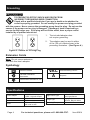
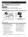
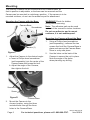
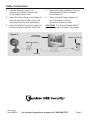
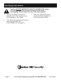
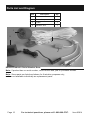
Owner’s Manual & Safety Instructions
Save This Manual Keep this manual for the safety warnings and precautions, assembly, operating,
inspection, maintenance and cleaning procedures. Write the product’s serial number in the back of the manual
near the assembly diagram (or month and year of purchase if product has no number).
Keep this manual and the receipt in a safe and dry place for future reference.
REV 14d
Visit our website at: http://www.harborfreight.com
Email our technical support at: [email protected]
When unpacking, make sure that the product is intact
and undamaged. If any parts are missing or broken,
please call 1-888-866-5797 as soon as possible.
Copyright© 2007 by Harbor Freight Tools®. All rights reserved.
No portion of this manual or any artwork contained herein may be reproduced in
any shape or form without the express written consent of Harbor Freight Tools.
Diagrams within this manual may not be drawn proportionally. Due to continuing
improvements, actual product may differ slightly from the product
described herein. Tools required for assembly and service may not be included.
Read this material before using this product.
Failure to do so can result in serious injury.
SAVE THIS MANUAL.
WARNING SYMBOLS AND DEFINITIONS
This is the safety alert symbol. It is used to alert you to
potential personal injury hazards. Obey all safety messages
that follow this symbol to avoid possible injury or death.
Indicates a hazardous situation which, if not avoided,
will result in death or serious injury.
Indicates a hazardous situation which, if not avoided,
could result in death or serious injury.
Indicates a hazardous situation which, if not avoided,
could result in minor or moderate injury.
Addresses practices not related to personal injury.
Important Safety Information
Read all safety warnings and instructions.
Failure to follow the warnings and instructions may result in
electric shock, fire and/or serious injury.
Save all warnings and instructions for future reference.
Installation Safety
1.
Keep children and bystanders away
while installing a camera. Distractions
can cause you to lose control.
2.
Do not overreach when installing
this product. Keep proper footing
and balance at all times. This enables
better control in unexpected situations.
3.
Wear ANSI-approved safety
goggles during installation.
4.
This product is not a toy. Mount
it out of reach of children.
Page 2
For technical questions, please call 1-888-866-5797.
Item 95914
Operation Safety
1. Do not operate electrically powered
5. WARNING: Handling the cord
products in explosive atmospheres,
on this product will expose you
such as in the presence of flammable
to lead, a chemical known to
liquids, gases, or dust. Electrically
the State of California to cause
powered products create sparks
cancer, and birth defects or other
which may ignite the dust or fumes.
reproductive harm. Wash hands
after handling. (California Health &
2. The adapter must match the outlet.
Safety Code § 25249.5, et seq.)
Never modify the plug in any way.
Unmodified plugs and matching outlets 6. The warnings, precautions, and
will reduce risk of electric shock.
instructions discussed in this instruction
manual cannot cover all possible
3. Do not expose the Power Adapter of
conditions and situations that may
this product to rain or wet conditions.
occur. It must be understood by the
Water entering the Power Adapter will
operator that common sense and
increase the risk of electric shock.
caution are factors which cannot
be built into this product, but must
4. Do not abuse the Power Cord. Never
be supplied by the operator.
use the cord for unplugging the plug
from the outlet. Keep cord away
from heat, oil, sharp edges or moving
parts. Damaged or entangled cords
increase the risk of electric shock.
Service Safety
1. Product service must be performed
only by a qualified technician.
2. When servicing a product, use
only identical replacement parts.
3. Maintain this product with care.
Keep this product clean. Do not use
a damaged product. Tag damaged
products “Do not use” until repaired.
4. Disconnect the Power Adapter
from the power source before
making any adjustments, changing
accessories, or storing this product.
Such preventive safety measures
reduce the risk of electric shock.
5. Maintain labels and nameplates
on the camera. These carry
important safety information. If
unreadable or missing, contact
Harbor Freight Tools for a replacement.
SAVE THESE INSTRUCTIONS.
Item 95914
For technical questions, please call 1-888-866-5797.
Page 3
Grounding
TO PREVENT ELECTRIC SHOCK AND DEATH FROM
INCORRECT GROUNDING WIRE CONNECTION:
Check with a qualified electrician if you are in doubt as to whether the
outlet is properly grounded. Do not modify the power cord plug provided
with the camera. Never remove the grounding prong from the plug. Do not use the
camera if the power cord or plug is damaged. If damaged, have it repaired by a
service facility before use. If the plug will not fit the outlet, have a proper outlet
installed by a qualified electrician.
1.
The included adapter does
not require grounding.
2.
The adapter may be used in either
of the 120 volt outlets shown in the
preceding illustration. (See Figure A.)
Figure A: Outlets for 2-Prong Plug
Extension Cords
Note: Do not use an extension
cord with this item’s adapter.
Symbology
Double Insulated
Canadian Standards
Association
VAC
A
Volts Alternating Current
Amperes
Underwriters Laboratories, Inc.
Specifications
Power Adapter
Resolution
Cable
Angle
Page 4
120 VAC / 60 Hz Input
9 VDC / 200 mA Output
300 x 380 TV lines
80 feet
40º down, 20º up,
360º side to side
Infrared LED’s with
Low Light Sensor
Daylight: Color
Image Type
Infrared: Black & White
Operating Temperature 14º to 122º F
Night Vision Type
For technical questions, please call 1-888-866-5797.
Item 95914
Installation Instructions
Read the ENTIRE IMPORTANT SAFETY INFORMATION section
at the beginning of this manual including all text under
subheadings therein before set up or use of this product.
TO PREVENT SERIOUS INJURY FROM ELECTRIC SHOCK:
Unplug the Power Adapter from its electrical outlet before installation.
Components
Power
Adapter (2)
Cable (3)
Adapter
Jack
Modular
Jack (4)
White
Yellow
Audio Plug Video Plug
Figure B
Cable
Phone
Jack
Adapter
Connector
Camera
Phone
Jack
Mounting
Screws
Camera (1)
Drywall
Anchors
Before Mounting
1.
Before mounting the Security Camera,
test the camera by connecting all
the cables and making sure that the
unit functions properly as described
in the following Set Up section.
c. Choose a location high enough so
that it is out of reach of children
and others who might tamper
with the unit, but still covers the
desired viewing area adequately.
2.
When planning the mounting
location and angle of the Camera,
consider the following:
d. Take into consideration the
length of the cable and the need
to place the Modular Jack (4)
in a safe, dry location.
Do not expose the modular Jack
to weather. Route the cord so
as to avoid a tripping hazard.
a. Do not mount the Camera in
bright or direct sunlight.
b. At night windows can reflect back
into the Camera, interfering with
the image. Test the Camera in the
intended location before mounting.
Rev 14d, 14d, 14d, 14d
Item 95914
For technical questions, please call 1-888-866-5797.
Page 5
Mounting
The Security Camera can be mounted with the Camera Base, so
that its position is adjustable, or the base can be removed and the
Camera can be mounted in a stationary position. If the camera is to be
mounted outdoors, do not use the adhesive pad for attachment.
Mounting the Camera with the Base
Camera Base
Screwdriver
WARNING! Check for hidden
wiring before securing.
Note: The adhesive pad can be used
instead of the screws for indoor locations.
Do not use adhesive pad to mount
outdoors, it is not weatherproof.
Mounting the Camera without the Base
1.
Using a Phillips head screwdriver
(sold separately), unthread the two
screws that hold the Camera Base in
place and remove the Camera Base.
Store in a dry safe place.
2.
Use the holes on the back of the
Camera to secure the unit in place.
Note the angle of the holes
when planning any drilling.
Camera (1)
Figure C
1.
Adjust the Camera to the desired angle:
a. Insert a Phillips head screwdriver
(sold separately) into the center of the
Camera base and loosen the bolt.
b. Adjust the angle of the Camera,
then tighten the bolt.
Screwdriver
Screw
Figure D
2.
Camera Base
Mount the Camera to the
chosen location, using the three
included bolts through the three
holes in the Camera Base.
Page 6
For technical questions, please call 1-888-866-5797.
Rev 07i, 08j, 10a, 10l
Item 95914
Cable Connection
1.
Use the Modular Jack (4) to
connect the Camera Phone Jack
to the Cable Phone Jack.
4.
Insert the Power Adapter’s (2) plug
into the black Power Connector
of the Cable (3).
2.
Insert the Yellow Plug of the Cable (3)
into the television’s Video Input Port
(television/monitor sold separately).
5.
Then, plug the Power Adapter (2)
into the nearest 120 volt,
grounded, electrical outlet.
3.
Insert the White Plug of the Cable (3)
into the television’s Audio Input Port.
CAUTION! The Power Adapter MUST
be used indoors in a clean, dry location.
Figure E
TELEVISION
(NOT INCLUDED)
POWER ADAPTER (2)
MODULAR JACK (4)
CABLE (3)
REV 07i, 09g
Item 95914
For technical questions, please call 1-888-866-5797.
Page 7
Operating Instructions
Read the ENTIRE IMPORTANT SAFETY INFORMATION section
at the beginning of this manual including all text under
subheadings therein before set up or use of this product.
1.
Turn on the television and set to
video/AV mode. The camera’s view
should appear on the screen.
2.
The Camera will operate continuously
(day and night) while the
Power Adapter (2) is plugged in.
Page 8
3.
When not using the Camera,
unplug the Power Adapter (2)
from the electrical outlet.
For technical questions, please call 1-888-866-5797.
Item 95914
Inspection, Maintenance, and Cleaning
Procedures not specifically explained in this manual must
be performed only by a qualified technician.
TO PREVENT SERIOUS INJURY FROM ELECTRIC SHOCK:
Unplug the Power Adapter from its electrical outlet
before inspection, maintenance, or cleaning.
1.
BEFORE EACH USE, inspect the
general condition of the Camera.
Check for loose screws, misalignment
or binding of moving parts, cracked
or broken parts, damaged electrical
wiring, and any other condition
that may affect its safe operation.
If a problem occurs, have the problem
corrected before further use.
Do not use damaged equipment.
2.
WEEKLY: Wipe off Camera Lens with
a soft, clean, moist cloth. Then dry.
Troubleshooting
Problem
Possible Causes
Probable Solutions
Camera does not work.
1. No power at outlet.
2. Cables not properly
connected.
1. Check power at outlet.
2. Check that all cables are
securely connected.
Poor image quality.
Camera lens is dirty.
Clean Camera lens.
View undesirable.
Camera out of adjustment.
Adjust Camera up, down, left, and
right to obtain desired view.
Image on the television
is upside down.
Camera not mounted correctly.
Reposition camera mount to mounting holes
at the top rear of the camera (see page 8).
REV 14d
Item 95914
For technical questions, please call 1-888-866-5797.
Page 9
Parts List and Diagram
Part
Description
Qty
1
Camera
1
2
Power Adapter
1
3
Cable
1
4
Modular Jack
1
1
2
3
4
Record Product’s Serial Number Here:
Note: If product has no serial number, record month and year of purchase instead.
Note: Some parts are listed and shown for illustration purposes only,
and are not available individually as replacement parts.
Page 10
For technical questions, please call 1-888-866-5797.
Item 95914
PLEASE READ THE FOLLOWING CAREFULLY
THE MANUFACTURER AND/OR DISTRIBUTOR HAS PROVIDED THE PARTS LIST AND
ASSEMBLY DIAGRAM IN THIS MANUAL AS A REFERENCE TOOL ONLY. NEITHER THE
MANUFACTURER OR DISTRIBUTOR MAKES ANY REPRESENTATION OR WARRANTY
OF ANY KIND TO THE BUYER THAT HE OR SHE IS QUALIFIED TO MAKE ANY
REPAIRS TO THE PRODUCT, OR THAT HE OR SHE IS QUALIFIED TO REPLACE ANY
PARTS OF THE PRODUCT. IN FACT, THE MANUFACTURER AND/OR DISTRIBUTOR
EXPRESSLY STATES THAT ALL REPAIRS AND PARTS REPLACEMENTS SHOULD
BE UNDERTAKEN BY CERTIFIED AND LICENSED TECHNICIANS, AND NOT BY THE
BUYER. THE BUYER ASSUMES ALL RISK AND LIABILITY ARISING OUT OF HIS OR
HER REPAIRS TO THE ORIGINAL PRODUCT OR REPLACEMENT PARTS THERETO, OR
ARISING OUT OF HIS OR HER INSTALLATION OF REPLACEMENT PARTS THERETO.
Item 95914
For technical questions, please call 1-888-866-5797.
Page 11
Limited 90 Day Warranty
Harbor Freight Tools Co. makes every effort to assure that its products meet high
quality and durability standards, and warrants to the original purchaser that this product
is free from defects in materials and workmanship for the period of 90 days from the
date of purchase. This warranty does not apply to damage due directly or indirectly,
to misuse, abuse, negligence or accidents, repairs or alterations outside our facilities,
criminal activity, improper installation, normal wear and tear, or to lack of maintenance.
We shall in no event be liable for death, injuries to persons or property, or for incidental,
contingent, special or consequential damages arising from the use of our product.
Some states do not allow the exclusion or limitation of incidental or consequential
damages, so the above limitation of exclusion may not apply to you. THIS WARRANTY
IS EXPRESSLY IN LIEU OF ALL OTHER WARRANTIES, EXPRESS OR IMPLIED,
INCLUDING THE WARRANTIES OF MERCHANTABILITY AND FITNESS.
To take advantage of this warranty, the product or part must be returned to us
with transportation charges prepaid. Proof of purchase date and an explanation
of the complaint must accompany the merchandise. If our inspection verifies
the defect, we will either repair or replace the product at our election or we may
elect to refund the purchase price if we cannot readily and quickly provide you
with a replacement. We will return repaired products at our expense, but if we
determine there is no defect, or that the defect resulted from causes not within the
scope of our warranty, then you must bear the cost of returning the product.
This warranty gives you specific legal rights and you may also
have other rights which vary from state to state.
3491 Mission Oaks Blvd. • PO Box 6009 • Camarillo, CA 93011 • 1-888-866-5797