1
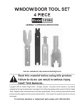
T-POST LIFTER
38444
ASSEMBLY & OPERATING INSTRUCTIONS
Revised 03/07
THANK YOU for choosing a HARBOR FREIGHT TOOLS product. For future reference, please complete
the owner’s record below:
Model
Serial No
Purchase Date
SAVE THE RECEIPT, WARRANTY AND THESE INSTRUCTIONS. It is important that you read the entire
manual to become familiar with the unit BEFORE you begin assembly.
The Operator
COMMON SENSE AND CAUTION ARE FACTORS WHICH CANNOT BE BUILT INTO ANY PRODUCT.
THESE FACTORS MUST BE SUPPLIED BY THE OPERATOR. PLEASE REMEMBER:
Do not use the product if under the influence of alcohol or drugs. Read warning labels on prescriptions to
determine if your judgment/reflexes might be impaired.
Do not wear loose clothing or jewelry as they can be caught in moving parts.
Protective gloves and non-skid footwear is recommended.
Use eye and ear protection. Always wear: ANSI-approved impact safety goggles.
Maintain proper footing and balance at all times.
Work Area
TO AVOID RISK OF PERSONAL INJURY, EQUIPMENT DAMAGE, FIRE AND SHOCK, MAKE SURE YOUR
WORK AREA IS:
Free of damp, wet or rainy conditions
Free of children (never let them handle tools or machinery)
Well-lit
Clean and uncluttered
Before Operating
Before using any tool, any part that appears damaged should be carefully checked to determine that it will
operate properly and perform its intended function.
Before using your T-Post Lifter check for damaged parts. You should also make sure all clamps, locks and
bolts are tight.
IF THERE IS ANY QUESTION ABOUT A CONDITION BEING SAFE OR UNSAFE, DO NOT OPERATE THE TOOL.
#38444
Page 2
Technical Specifications
Tool Name:
SKU:
Base Dimensions:
Base:
Weight:
T-Post Lifter
38444
37 1/2" x 1 3/4“ x 7/64”
34“ x 1“ x 1/8“ Thick Steel Tubing
10 Lbs.
Product Use:
The T-Post Lifter lifts up used T-Posts with ease, even from hard or frozen ground.
Assembly
Step 1)
Attach Handle (part #3) to Base (part #1) by inserting the Axle (part #7)
into the Base and through the holes in the Handle. Insert Cotter Pin (part # 6)
into Axle to firmly secure Handle (See Parts Diagram below).
Step 2)
Line up the upper circular tube portion of U-Block (part #2) with tubing at the top
of the Handle (part #3). Insert the Shaft (part # 5) through the Washer (part # 4)and
secure with the Cotter Pin (part # 6) (See Parts Diagram below).
Operation
Making sure Base (part #1) is stable, insert T-Post into open end of U-Block (part #2). Push down on Handle
to pull up T-Post.
Parts List
Part Number
1
2
3
4
5
6
7
#38444
Description
Base
U - Block
Handle
Washer
Shaft
Cotter Pin
Axle
Quantity
1
1
1
1
1
2
1
Page 3