1
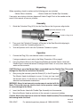
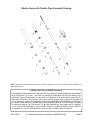
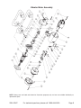
CONCRETE VIBRATOR MOTOR
WITH FRAME
42947
ASSEMBLY AND OPERATING
INSTRUCTIONS
Distributed Exclusively by Harbor Freight Tools®.
3491 Mission Oaks Blvd., Camarillo, CA 93011
Visit our Web site at http://www.harborfreight.com
Copyright © 2000 by Harbor Freight Tools. All rights reserved. No portion of this
manual or any artwork contained herein may be reproduced in any shape or
form without the express written consent of Harbor Freight Tools.
For technical questions and replacement parts, please call 1-800-444-
Specifications
Motor
4000 RPM; 2.2 HP; coated windings; thermo
protection
Power Requirement
110 Volt, 60 Hz, 15 amp
Shaft
Counterclockwise Rotation; sealed bearings
1.437 (Dia.) x 18 feet, 5 inches (L)
Center Shaft: 0.497 inches
Vibrator Head and Hose
Connector ID: 1.497 inches
Hose: 1.157 (Dia.) inches
Line Cord
13 feet; wire: 16 AWG, 2-prong grounded
plug, UL listed
Motor and Frame Weight 16 lb.
Vibrator Head and Hose 27 lb.
Save This Manual
You will need the manual for the safety warnings and precautions, assembly instructions,
operating and maintenance procedures, parts list and diagram. Keep your invoice with this
manual. Write the invoice number on the inside of the front cover. Keep the manual and
invoice in a safe and dry place for future reference.
Safety Warnings and Precautions
WARNING: When using tool, basic safety precautions should always be followed to
reduce the risk of personal injury and damage to equipment.
Read all instructions before using this tool!
1.
Keep work area clean. Cluttered areas invite injuries.
2.
Observe work area conditions. Do not use machines or power tools in damp or wet
locations. Don’t expose to rain. Keep work area well lighted. Do not use electrically
powered tools in the presence of flammable gases or liquids.
3.
Keep children away. Children must never be allowed in the work area. Do not let them
handle machines, tools, or extension cords.
4.
Store idle equipment. When not in use, tools must be stored in a dry location to inhibit
rust. Always lock up tools and keep out of reach of children.
5.
Do not force tool. It will do the job better and more safely at the rate for which it was
intended. Do not use inappropriate attachments in an attempt to exceed the tool
capacity.
6.
Use the right tool for the job. Do not attempt to force a small tool or attachment to do
the work of a larger industrial tool. There are certain applications for which this tool was
designed. Do not modify this tool and do not use this tool for a purpose for which it was
not intended.
SKU 42947
For technical questions, please call 1-800-444-3353.
Page 7.
Dress properly. Do not wear loose clothing or jewelry as they can be caught in
moving parts. Protective, electrically non-conductive clothes and non-skid footwear are
recommended when working. Wear restrictive hair covering to contain long hair.
8.
Use eye and ear protection. Always wear ANSI-approved impact safety goggles. Wear a
full face shield if you are producing metal filings or wood chips. Wear a NIOSH-approved
dust mask or respirator when working around metal, wood, and chemical dusts and
mists.
9.
Do not overreach. Keep proper footing and balance at all times. Do not reach over or
across running machines.
10. Maintain tools with care. Keep tools sharp and clean for better and safer performance.
Inspect tool cords periodically and, if damaged, have them repaired by a qualified
technician.
11. Disconnect power. Unplug motor when not in use.
12. Avoid unintentional starting. Be sure the switch is in the Off position when not in use
and before plugging in. Do not carry any tool with the unit plugged in.
13. Stay alert. Watch what you are doing, use common sense. Do not operate any tool when
you are tired.
14. Check for damaged parts. Before using any tool, any part that appears damaged
should be carefully checked to determine that it will operate properly and perform its
intended function. Check for alignment and binding of moving parts; any broken parts
or mounting fixtures; and any other condition that may affect proper operation. Any part
that is damaged should be properly repaired or replaced by a qualified technician. Do
not use the tool if any switch does not turn On and Off properly.
15. Guard against electric shock. Prevent body contact with grounded surfaces such as
pipes, radiators, ranges, and refrigerator enclosures.
16. Replacement parts and accessories. When servicing, use only identical replacement
parts. Use of any other parts will void the warranty. Only use accessories intended for
use with this tool. Approved accessories are available from Harbor Freight Tools.
17. Do not operate tool if under the influence of alcohol or drugs. Read warning labels
on prescriptions to determine if your judgment or reflexes are impaired while taking drugs.
If there is any doubt, do not operate the tool.
18. Use proper size and type extension cord. If an extension cord is required, it must be
of the proper size and type to supply the correct current to the tool without heating up.
Otherwise, the extension cord could melt and catch fire, or cause electrical damage to
the tool. This tool requires use of an extension cord of 0 to 15 amps capability (up to 50
feet), with wire size rated at 16 AWG. Longer extension cords require larger size wire. If
you are using the tool outdoors, use an extension cord rated for outdoor use (signified
by “WA” on the jacket).
19. Maintenance. For your safety, service and maintenance should be performed regularly
by a qualified technician.
Note: Performance of this tool may vary depending on variations in local line voltage. Extension
SKU 42947
For technical questions, please call 1-800-444-3353.
Page cord usage may also affect tool performance.
Warning: The warnings, cautions, and instructions discussed in this instruction manual
cannot cover all possible conditions and situations that may occur. It must be understood
by the operator that common sense and caution are factors which cannot be built into
this product, but must be supplied by the operator.
Vibration Hazard
This tool vibrates during use. Repeated or long-term exposure to vibration may
cause temporary or permanent physical injury, particularly to the hands, arms and
shoulders. To reduce the risk of vibration-related injury:
1.
Anyone using vibrating tools regularly or for an extended period should first be
examined by a doctor and then have regular medical check-ups to ensure medical
problems are not being caused or worsened from use. Pregnant women or people
who have impaired blood circulation to the hand, past hand injuries, nervous system
disorders, diabetes, or Raynaud’s Disease should not use this tool. If you feel any
medical or physical symptoms related to vibration (such as tingling, numbness, and
white or blue fingers), seek medical advice as soon as possible.
2.
Do not smoke during use. Nicotine reduces the blood supply to the hands and
fingers, increasing the risk of vibration-related injury.
3.
Wear suitable gloves to reduce the vibration effects on the user.
4.
Use tools with the lowest vibration when there is a choice between different
processes.
5.
Include vibration-free periods each day of work.
6.
Grip tool as lightly as possible (while still keeping safe control of it). Let the tool do
the work.
7.
To reduce vibration, maintain the tool as explained in this manual. If any abnormal
vibration occurs, stop use immediately.
REV 07j
SKU 42947
For technical questions, please call 1-800-444-3353.
Page Unpacking
When unpacking, check to make sure the following parts are included:
- Vibrator Motor Assembly
- Vibrator Head with Flexible Pipe Assembly
If any parts are missing or broken, please call Harbor Freight Tools at the number on the
cover of this manual as soon as possible.
Assembly
1.
Guide the Cylindrical Plug (A14) into the Gear Box so that its grooves align inside.
Cylindrical Connector (A16)
Grooves
Cylindrical Plug (A14)
Notches
2.
Then, push the Cylindrical Connector all the way in the Gear Box while aligning its
notches to meet the Connecting Spanner (1).
3.
Turn the Spanner until it locks the Cylindrical Connector in place.
Operation
1.
Connect the Plug (19) to an electrical outlet or extension cord.
If using an extension cord, refer to the Safety Precaution #18 on page 3.
2.
Carry the Vibrator Motor by the Supporting Bracket (8) and the Vibrator Head with
Flexible Pipe to where the cement is being poured. Place it in a dry area, away from
water and the concrete.
CAUTION: Never carry the Vibrator Motor suspended from the Flexible Pipe. This could
Switch (51)
damage the Gear Box or Cylindrical Connector.
3.
After pouring the concrete, press the Switch (51) to the ON position.
The Vibrator Head should begin to move. If it does not, tap it until
the vibration starts. If it still does not, turn the unit OFF and recheck
electrical and mechanical connections.
WARNING: Never let wet concrete or water come in contact with the
Motor. This could cause an electric shock to the operator, viewers,
or cause damage to the Motor.
4.
Insert the Vibrator Head with Flexible Pipe Assembly into the concrete.
5.
Move the Vibrator Head up and down in the concrete to remove air bubbles.
Caution: Never allow concrete to enter the Vibrator Head Assembly. This could damage
the bearing inside the Head.
REV 05/06
SKU 42947
For technical questions, please call 1-800-444-3353.
Page 6.
When finished, press the Switch to the OFF position and unplug the unit from the
electrical outlet.
7.
Immediately wash down the Vibrator Head and Flexible Pipe with clean water. Wipe
dry with a clean cloth.
Be careful not to wet the Vibrator Motor Assembly during cleaning.
Maintenance
1.
Clean all components with a damp cloth after every use. Remove all concrete residue.
2.
After more than 100 hours of use, the Vibrating Head Assembly and Flexible Pipe
Assembly may require cleaning and lubrication. This should only be done by a
qualified technician.
Vibrator Head with Flexible Pipe Parts List
Item
Description
Qty
Item
Description
Qty
A1
Cone
1
A9
Bearing, 202U
1
A2
Spacer
1
A10
Pipe Adaptor
1
A3
Raceway
1
A11
Shaft Adaptor
1
A4
Casing
1
A12
Flexible Shaft
1
A5
Rolling Body
1
A13
Flexible Pipe
1
A6
Oil Seal Ring, 24 x 2.4
1
A14
Cylindrical Plug
1
A7
Oil Seal Housing
1
A15
Conical Sleeve
1
A8
Oil Seal, PD 14 x 24 x 7
1
A16
Cylindrical Connector
1
SKU 42947
For technical questions, please call 1-800-444-3353.
Page Vibrator Head with Flexible Pipe Assembly Drawing
NOTE: Some parts are listed and shown for illustration purposes only and are not available individually as
replacement parts.
PLEASE READ THE FOLLOWING CAREFULLY
THE MANUFACTURER AND/OR DISTRIBUTOR HAS PROVIDED THE PARTS DIAGRAM IN THIS MANUAL
AS A REFERENCE TOOL ONLY. NEITHER THE MANUFACTURER NOR DISTRIBUTOR MAKES ANY
REPRESENTATION OR WARRANTY OF ANY KIND TO THE BUYER THAT HE OR SHE IS QUALIFIED TO
MAKE ANY REPAIRS TO THE PRODUCT OR THAT HE OR SHE IS QUALIFIED TO REPLACE ANY PARTS
OF THE PRODUCT. IN FACT, THE MANUFACTURER AND/OR DISTRIBUTOR EXPRESSLY STATES THAT
ALL REPAIRS AND PARTS REPLACEMENTS SHOULD BE UNDERTAKEN BY CERTIFIED AND LICENSED
TECHNICIANS AND NOT BY THE BUYER. THE BUYER ASSUMES ALL RISK AND LIABILITY ARISING
OUT OF HIS OR HER REPAIRS TO THE ORIGINAL PRODUCT OR REPLACEMENT PARTS THERETO,
OR ARISING OUT OF HIS OR HER INSTALLATION OF REPLACEMENT PARTS THERETO.
SKU 42947
For technical questions, please call 1-800-444-3353.
Page Vibrator Motor Assembly Parts List
Item
Description
Qty
Item
Description
Qty
1
Connecting Spanner
1
28
First Driven Gear
1
2
Gear Box
1
29
Main Shaft
1
3
Stop Screw, 5x10
1
30
Bearing, 60105
1
4
Rivet, 2.5x5
1
31
Rubber Washer, II
1
5
Push Block
1
32
Cover Plate
1
6
Circlip 25
1
33
Roller Pin, 2.5x27
1
7
Plain Washer, 8-140HV
4
34
Name Plate
1
8
Supporting bracket
1
35
Circlip 12
1
9
Flat Key, 5x12
1
36
Screw, ST5.5x55-C
4
10
Plain Washer, 8-140HV
4
37
Stator Assembly
1
11
Bolt, M8x30
4
38
Screw, ST5.5x80-C-H
2
12
Suporting Spacer
4
39
Bearing Cover
1
13
Stop Screw, 5x10
1
40
Motor Housing
1
14
Armature Assembly
1
41
Rubber Washer, I
1
15
Dust-proof Cover, 100
1
42
Cover Plate
1
16
Bearing, 60100
1
43
Screw, ST4.2x25-C
2
17
Wind-block Plate
1
44
Brush Housing, 8x16
2
18
End Cover
1
45
Brush Assembly, 8x16x18
2
19
Plug Assembly, 1x4.7
1
46
Screw, ST4.2x13-C-H
4
20
Rear Cover
1
47
Cable Pressing Plate
1
21
Cable Protector, 9
1
48
Screw, M4x10
2
22
Water-proof Switch Cover
1
49
Switch Base
1
23
Bearing, 60102
1
50
Screw, ST4.2x13-C-H
2
24
Breaker, 0.2u+4700Px2
1
51
Switch, DPST-16
1
25
Mid-cover
1
52
Nut Screw, M8
4
26
Bearing, 12E8x16x12
1
53
Screw, ST4.8x90-C
4
27
Oil Seal Ring
1
SKU 42947
For technical questions, please call 1-800-444-3353.
Page Vibrator Motor Assembly
NOTE: Some parts are listed and shown for illustration purposes only and are not available individually as
replacement parts.
SKU 42947
For technical questions, please call 1-800-444-3353.
Page LIMITED 90 DAY WARRANTY
Harbor Freight Tools Co. makes every effort to assure that its products meet high quality
and durability standards, and warrants to the original purchaser that this product is free from
defects in materials and workmanship for the period of 90 days from the date of purchase. This
warranty does not apply to damage due directly or indirectly, to misuse, abuse, negligence or
accidents, repairs or alterations outside our facilities, criminal activity, improper installation,
normal wear and tear, or to lack of maintenance. We shall in no event be liable for death,
injuries to persons or property, or for incidental, contingent, special or consequential damages
arising from the use of our product. Some states do not allow the exclusion or limitation of
incidental or consequential damages, so the above limitation of exclusion may not apply to
you. This warranty is expressly in lieu of all other warranties, express
or implied, including the warranties of merchantability and fitness.
To take advantage of this warranty, the product or part must be returned to us with
transportation charges prepaid. Proof of purchase date and an explanation of the complaint
must accompany the merchandise. If our inspection verifies the defect, we will either repair or
replace the product at our election or we may elect to refund the purchase price if we cannot
readily and quickly provide you with a replacement. We will return repaired products at our
expense, but if we determine there is no defect, or that the defect resulted from causes not
within the scope of our warranty, then you must bear the cost of returning the product.
This warranty gives you specific legal rights and you may also have other rights which
vary from state to state.
3491 Mission Oaks Blvd. • PO Box 6009 • Camarillo, CA 93011 • (800) 444-3353
REV 07j
SKU 42947
For technical questions, please call 1-800-444-3353.
Page 10