1
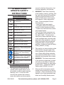
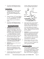
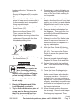
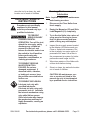
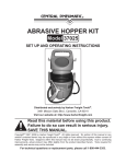
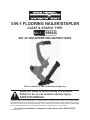
3-IN-1 FLOORING NAILER/STAPLER
CLEAT & STAPLE TYPE
99640
SET UP AND OPERATING INSTRUCTIONS
Visit our website at: http://www.harborfreight.com
Read this material before using this product.
Failure to do so can result in serious injury.
SAVE THIS MANUAL.
Copyright© 2008 by Harbor Freight Tools®. All rights reserved. No portion of this manual or any artwork contained
herein may be reproduced in any shape or form without the express written consent of Harbor Freight Tools. Diagrams
within this manual may not be drawn proportionally. Due to continuing improvements, actual product may differ slightly
from the product described herein. Tools required for assembly and service may not be included.
For technical questions or replacement parts, please call 1-800-444-3353.
Revised Manual 10d
SAVE THIS MANUAL
NOTICE is used to
address practices
not related to personal injury.
Keep this manual for the safety warnings and precautions, assembly, operating, inspection, maintenance and cleaning
procedures. Write the product’s serial
number in the back of the manual near the
assembly diagram (or month and year of
purchase if product has no number). Keep
this manual and the receipt in a safe and
dry place for future reference.
Safety Alert Symbol and Signal
Words
In this manual, on the labeling,
and all other information provided with this product:
This is the safety alert
symbol. It is used to alert
you to potential personal
injury hazards. Obey all
safety messages that
follow this symbol to avoid
possible injury or death.
DANGER indicates
a hazardous
situation which, if not
avoided, will result in death or
serious injury.
WARNING
indicates a
hazardous situation which, if
not avoided, could result in
death or serious injury.
CAUTION, used
with the safety
alert symbol, indicates a
hazardous situation which, if
not avoided, could result in
minor or moderate injury.
SKU 99640
CAUTION, without
the safety alert
symbol, is used to address
practices not related to
personal injury.
IMPORTANT SAFETY
INSTRUCTIONS
INSTRUCTIONS PERTAINING
TO A RISK OF FIRE,
ELECTRIC SHOCK, OR
INJURY TO PERSONS
WARNING – When using
tools, basic precautions
should always be followed,
including the following:
To reduce the risks of electric shock,
fire, and injury to persons, read all the
instructions before using the tool.
Work area
a.
Keep the work area clean and well
lighted. Cluttered benches and dark
areas increase the risks of electric
shock, fire, and injury to persons.
b.
Do not operate the tool in explosive atmospheres, such as in the
presence of flammable liquids,
gases, or dust. The tool is able to
create sparks resulting in the ignition
of the dust or fumes.
c.
Keep bystanders, children, and
visitors away while operating the
tool. Distractions are able to result in
the loss of control of the tool.
For technical questions, please call 1-800-444-3353.
Page 2
Personal safety
a.
b.
c.
Stay alert. Watch what you are doing and use common sense when
operating the tool. Do not use the
tool while tired or under the influence of drugs, alcohol, or medication. A moment of inattention while
operating the tool increases the risk
of injury to persons.
Dress properly. Do not wear loose
clothing or jewelry. Contain long
hair. Keep hair, clothing, and
gloves away from moving parts.
Loose clothes, jewelry, or long hair
increases the risk of injury to persons
as a result of being caught in moving
parts.
Avoid unintentional starting. Be
sure the switch is off before connecting to the air supply. Do not
carry the tool with your finger on the
switch or connect the tool to the air
supply with the switch on.
d.
Remove adjusting keys and
wrenches before turning the tool
on.
e.
Do not overreach. Keep proper
footing and balance at all times.
Proper footing and balance enables
better control of the tool in unexpected situations.
f.
Use safety equipment. A
dust mask, non-skid safety
shoes and a hard hat must
be used for the applicable
conditions. Wear heavy-duty work
gloves during use. Wear a full face
shield if you are producing metal
filings or wood chips.
SKU 99640
g.
Always wear eye protection. Wear ANSI-approved safety goggles with
side shields during use.
h.
Always wear hearing
protection when using
the tool. Prolonged exposure to high intensity noise
is able to cause hearing loss.
Tool use and care
a.
Avoid unintentional
misfires. Always use
caution to avoid accidentally striking Hammer Face (2). Do not point
tool towards yourself or anyone or
whether it contains nails/staples or
not.
b.
Do not load fasteners when Nailer
is connected to air hose. Always
assume tool contains fasteners. Unintentional firing may occur.
c.
Fire cleat nails and staples into
an appropriate work surface only.
Do not attempt to fire cleat nails or
staples into surfaces too hard to
penetrate. Do not drive cleat nails
or staples on top of other cleat nails
or staples, or at too steep an angle.
Cleat nails and staples can ricochet,
causing personal injury. Never fire
this tool into the air or point it toward
yourself or another person.
d.
Hold tool away from head and
body during use. Tool may kick
back, causing injury.
e.
Do not fire cleat nails or staples
too close to edge of workpiece.
They may split the workpiece and fly
free, causing personal injury.
For technical questions, please call 1-800-444-3353.
Page 3
f.
Carry tool safely. Carry tool by
handle.
g.
Use clamps or another practical
way to secure and support the
workpiece to a stable platform.
Holding the work by hand or against
the body is unstable and is able to
lead to loss of control.
h.
i.
Do not force the tool. Use correct
tool for application. The correct tool
will do the job better and safer at the
rate for which the tool is designed.
Disconnect the tool from the air
source before making any adjustments, changing accessories, or
storing the tool. Such preventive
safety measures reduce the risk
of starting the tool unintentionally.
Turn off and detach the air supply
and safely discharge any residual
air pressure before leaving the work
area.
j.
Store the tool when it is idle out of
reach of children and other untrained persons. A tool is dangerous
in the hands of untrained users.
k.
Maintain the tool with care. Keep
tool clean. A properly maintained tool,
reduces the risk of binding and is
easier to control.
l.
m.
Check for misalignment or binding of moving parts, breakage of
parts, and any other condition that
affects the tool’s operation. If damaged, have the tool serviced before
using. Many accidents are caused
by poorly maintained tools. There is a
risk of bursting if the tool is damaged.
accessory not intended for use with
the specific tool model, increases the
risk of injury to persons.
Service
a.
Tool service must be performed
only by qualified repair personnel.
b.
When servicing a tool, use only
identical replacement parts. Use
only authorized parts.
c.
Use only the lubricants supplied
with the tool or specified by the
manufacturer.
Air source
a.
Never connect to an air
source that is capable of
exceeding 120 PSI. Over
pressurizing the tool may
cause bursting, abnormal operation,
breakage of the tool or serious injury
to persons. Use only clean, dry,
regulated compressed air at the rated
pressure or within the rated pressure
range as marked on the tool (70 to
120 PSI). Always verify prior to using
the tool that the air source has been
adjusted to the rated air pressure or
within the rated air-pressure range.
b.
Never use oxygen, carbon dioxide,
combustible gases or any bottled
gas as an air source for the tool.
Such gases are capable of explosion
and serious injury to persons.
SAVE THESE
INSTRUCTIONS.
Use only accessories that are
identified by the manufacturer for
the specific tool model. Use of an
SKU 99640
For technical questions, please call 1-800-444-3353.
Rev 09i
Page 4
SYMBOLS AND
SPECIFIC SAFETY
INSTRUCTIONS
cannot be built into this product, but
must be supplied by the operator.
2.
WARNING: Some dust created by
power sanding, sawing, grinding, drilling, and other construction activities,
contains chemicals known [to the
State of California] to cause cancer,
birth defects or other reproductive
harm. Some examples of these
chemicals are:
• Lead from lead-based paints
• Crystalline silica from bricks and
cement or other masonry products
• Arsenic and chromium from chemically treated lumber
Your risk from these exposures varies, depending on how often you do
this type of work. To reduce your
exposure to these chemicals: work in
a well ventilated area, and work with
approved safety equipment, such as
those dust masks that are specially
designed to filter out microscopic
particles. (California Health & Safety
Code § 25249.5, et seq.)
3.
Take caution, as some woods contain
preservatives such as copper chromium arsenate (CCA) which can be
toxic. When nailing these materials,
extra case should be taken to avoid
inhalation and minimize skin contact.
4.
WARNING: The brass components
of this product contain lead, a chemical known to the State of California
to cause birth defects (or other reproductive harm). (California Health &
Safety code § 25249.5, et seq.)
5.
Only use with accessories rated to
handle forces exerted by tool during
operation. Other accessories not designed for the forces generated may
break and forcefully launch pieces.
Symbol Definitions
Symbol
no
.../min
Property or statement
No-load speed
Revolutions or reciprocation per
minute
PSI
Pounds per square inch of pressure
ft-lb
Foot-pounds of torque
BPM
Blows per minute
CFM
Cubic Feet per Minute flow
SCFM
Cubic Feet per Minute flow at
standard conditions
NPT
National pipe thread, tapered
NPS
National pipe thread, straight
WARNING marking concerning Risk
of Eye Injury. Wear ANSI-approved
eye protection.
WARNING marking concerning Risk
of Hearing Loss. Wear hearing
protection.
WARNING marking concerning Risk
of Respiratory Injury. Wear NIOSHapproved dust mask/respirator.
WARNING marking concerning Risk
of Explosion.
Specific Safety Instructions.
1.
The warnings and precautions discussed in this manual cannot cover
all possible conditions and situations
that may occur. It must be understood by the operator that common
sense and caution are factors which
SKU 99640
For technical questions, please call 1-800-444-3353.
Page 5
6.
7.
8.
9.
Attach all accessories properly to the
tool before connecting the air supply. A loose accessory may detach or
break during operation.
Obey the manual for the air compressor used to power this tool.
Install in-line shutoff valve to allow
immediate control over air supply in
emergency, even if hose is ruptured.
Do not lay tool down until it has completely stopped. Moving parts can
grab surface and lead to control loss.
Vibration Precautions
This tool vibrates during use. Repeated or long-term exposure to vibration may cause temporary or permanent
physical injury, particularly to the hands,
arms and shoulders. To reduce the risk of
vibration-related injury:
1.
Anyone using vibrating tools regularly or for an extended period should
first be examined by a doctor and
then have regular medical checkups to ensure medical problems are
not being caused or worsened from
use. Pregnant women or people
who have impaired blood circulation
to the hand, past hand injuries, nervous system disorders, diabetes, or
Raynaud’s Disease should not use
this tool. If you feel any medical or
physical symptoms related to vibration (such as tingling, numbness, and
white or blue fingers), seek medical
advice as soon as possible.
2.
Do not smoke during use. Nicotine reduces the blood supply to the
hands and fingers, increasing the risk
of vibration-related injury.
SKU 99640
3.
Wear suitable gloves to reduce the
vibration effects on the user.
4.
Use tools with the lowest vibration
when there is a choice between different processes.
5.
Include vibration-free periods each
day of work.
6.
Grip tool as lightly as possible (while
still keeping safe control of it). Let
the tool do the work.
7.
To reduce vibration, maintain tool as
explained in this manual. If abnormal
vibration occurs, stop immediately.
SAVE THESE
INSTRUCTIONS.
For technical questions, please call 1-800-444-3353.
Page 6
refer to the Assembly Diagram near
the end of this manual.
SPECIFICATIONS
Air Pressure
Range
Maximum Air
Pressure
120 PSI
Air Inlet
1/4” -18 NPT
Fastener
Capacity and
Size Range
120 1/2” Crown Flooring Staples
Length: 1-1/2” to 2”
Gauge: 15 1/2 Ga
100 “L” or “T” Type Flooring Cleats
Length: 1-1/2” to 2”
Gauge: 16 Ga
Air
Consumption
4 SCFM @ 90 PSI
Safety Trigger
Accessories
• This tool may be shipped with the
Arm (80) detached from the main
body. If so, follow these instructions:
70-120 PSI
Arm (80)
Nut (70) and
Washer (71)
Slugging Actuation Only
(No Safety)
Wrench Set
Slugging Hammer
Air Coupler Adapter
Air Tool Oil Dropper
Spare Base Plate
UNPACKING
When unpacking, check to make sure
that the item is intact and undamaged. If
any parts are missing or broken, please
call Harbor Freight Tools at the number
shown throughout the manual as soon as
possible.
• This air tool may be shipped with a
protective plug covering the air inlet.
Remove this plug before set up.
ASSEMBLY
Read the ENTIRE IMPORTANT
SAFETY INFORMATION
section at the beginning of this
manual including all text under
subheadings therein before set
up or use of this product.
Bracket (72)
Handle (69)
Figure A
1.
Set the Arm against the Handle (69)
and slide the Brackets (72) through
the Arm holes slots and holes.
Thread Washers (71) and Nuts (70)
over ends of Brackets.
See Figure A.
2.
Wrench-tighten the Nuts until Brackets are secured and the Arm is locked
against Handle.
Air Supply Setup
TO PREVENT
EXPLOSION:
Use only clean, dry, regulated,
compressed air to power tool.
Do not use oxygen, carbon
dioxide, combustible gases,
or any other bottled gas as a
power source for tool.
Note: For additional information regarding
the parts listed in the following pages,
REV 08j; 09c; 09i
SKU 99640
For technical questions, please call 1-800-444-3353.
Page 7
pressure and operate accidentally
after the air supply is disconnected.
Note: Air flow, and therefore tool performance, can be hindered by undersized air supply components.
1.
Incorporate an in-line oiler, shut-off
valve, regulator with pressure gauge,
and filter for best service, as shown in
the diagram above. An in-line shutoff valve is an important safety
device because it controls the air
supply even if the air hose is ruptured.
Note: If an automatic oiler system is not
used, add a few drops of Pneumatic
Tool Oil to the airline connection before operation. Add a few more drops
after each hour of continual use.
2.
Attach an air hose to the compressor’s air outlet. Connect the air hose
to the air inlet of the tool. Other components, such as a connector and
quick coupler, will make operation
more efficient, but are not required.
WARNING! TO PREVENT SERIOUS
INJURY FROM ACCIDENTAL
OPERATION: Do not install a
female quick coupler on the tool.
Such a coupler contains an air valve
that will allow the air tool to retain
SKU 99640
3.
The air hose must be long enough
to reach the work area with enough
extra length to allow free movement
while working.
4.
Close the in-line safety valve between the compressor and the tool.
5.
Turn on the air compressor according
to the manufacturer’s directions and
allow it to build up pressure until it
cycles off.
6.
Adjust the air compressor’s output
regulator so that the air output is
enough to properly power the tool,
but the output will not exceed the
tool’s maximum air pressure at any
time. Adjust the pressure gradually,
while checking the air output gauge
to set the right pressure range.
7.
Inspect the air connections for leaks.
Repair any leaks found.
8.
If the tool will not be used at this time,
turn off and detach the air supply
and safely discharge any residual air
pressure.
Note: Residual air pressure should not be
present after the tool is disconnected
from the air supply. However, it is a
good safety measure to attempt to
discharge the tool in a safe fashion
after disconnecting to ensure that the
tool is disconnected and unpowered.
For technical questions, please call 1-800-444-3353.
Page 8
To Attach An Air Connector:
1.
Attach a 1/4” Connector (not included) to the Adapter (82) prior to operation.
2.
Wrap about 3” of pipe thread seal
tape (not included) onto threads of
the Connector before attaching it to
the Adapter.
TO PREVENT SERIOUS
INJURY: Do not adjust or
tamper with any control or
component in a way not
specifically explained within
manual. Improper adjustment
can result in tool failure or
other serious hazards.
WARNING! Disconnect the Floor
Nailer from the air compressor whenever loading or servicing. After disconnecting the Floor Nailer from the
air compressor, there could still be
enough air pressure to fire the Nailer.
After the air hose is disconnected,
always fire the Nailer into scrap wood
repeatedly to make sure all of the
compressed air is expended.
OPERATING INSTRUCTIONS
Read the ENTIRE IMPORTANT
SAFETY INFORMATION
section at the beginning of this
manual including all text under
subheadings therein before set
up or use of this product.
Inspect tool before use, looking
for damaged, loose, and
missing parts. If any problems
are found, do not use tool until
repaired.
Loading Cleat Nails:
Safety
Lock (54)
Loading Nails and Staples
TO PREVENT
SERIOUS INJURY
FROM ACCIDENTAL
OPERATION: Detach the air
supply, safely discharge any
residual air pressure in the
tool, and release the throttle
and/or turn the switch to its
off position before performing
any inspection, maintenance,
or cleaning procedures.
SKU 99640
Side Load
Magazine
(61)
Magazine
(52)
Pusher (56)
1.
Pull the Pusher (56) back to end of
Magazine (52). Lock Pusher in place
by using Safety Lock (54). Then pull
Side Load Magazine (61) back.
2.
Place full clip of desired fasteners
into Magazine (61) from the side.
Up to 100 Cleat Nails may be loaded
into Nailer.
For technical questions, please call 1-800-444-3353.
REV 09i, 10d
Page 9
3.
Push Side Load Magazine forward
and press Lock to unfasten Pusher.
surface, making sure the Spacer is
over the nail/staple target position.
Loading Staples:
1.
2.
3.
Pull the Pusher (56) back to the end
of Magazine (52). Lock Pusher in
place by using Safety Lock (54).
Then pull Side Load Magazine (61)
back.
Hand Grip (81)
Hammer (1)
Hammer
Face (2)
Place a full clip of 1/2” Crown Staples
or 1-1/2” - 2” Cleat Nails in the Magazine (52) from the top. Up to 120
Crown Staples may be loaded into
Nailer.
Push Side Load Magazine forward
and press Lock to unfasten Pusher.
Work Surface
6.
Press down hard so that the Spacer
(36) is firmly contacting the work
surface. Then, using the Hammer (1),
strike the Hammer Face (2) firmly
to drive the fastener into work surface. Lift the Floor Nailer off the work
surface. Repeat this process until the
job is completed.
7.
WARNING! After disconnecting Nailer from air compressor, there could
still be enough air pressure to fire
Nailer. After the air hose is disconnected, always fire Nailer into scrap
wood repeatedly to make sure all of
compressed air is expended.
8.
When finished, make sure to store
the Floor Nailer in a clean, dry, safe
location out of reach of children and
other unauthorized people.
Operating Floor Nailer
1.
2.
WARNING! Extreme caution must
be used whenever this tool is connected to an air supply. If the tool is
dropped, or if the Hammer Face (2) is
accidentally struck, then the tool will
fire a nail or staple, potentially causing SEVERE PERSONAL INJURY.
Attach the Floor Nailer to the air supply at the Quick Connector. Start
your compressor and check the
pressure, making sure it is set at the
recommended 70-120 PSI. Do not
exceed the maximum 120 PSI.
3.
WARNING! Keep your feet clear of
the Floor Nailer.
4.
NOTE: Before using on a floor, test
the tool on a scrap piece of wood.
Adjust the driving depth by providing more or less air pressure. Never
exceed 120 PSI.
5.
Hold the Hand Grip (81) securely and
press the Spacer (36) to the work
SKU 99640
Spacer
(37)
To Change The Spacer:
The Floor Nailer is designed to install
1/2” and 25/32” hardwood flooring.
The tool is factory set with a 1/4” thick
shoe plate for 25/32” hardwood flooring. An additional 5/16” thick shoe
plate is also include for installing 1/2”
For technical questions, please call 1-800-444-3353.
Rev 09i, 10d
Page 10
hardwood flooring. To change the
Spacer:
4.
Occasionally, a cleat nail/staple may
become jammed in the firing mechanism of the Floor Nailer, making the
tool inoperable.
5.
To remove a jammed cleat nail/
staple, disconnect the tool from its air
supply, push in the Lock and slide the
Magazine back until it locks in place.
Then, lean the Floor Nailer back.
6.
Remove all cleat nails/staples from
the Magazine. Then press the Lock
and slide the Moveable Magazine
forward all the way.
7.
Attempt to fire the Floor Nailer into a
piece of scrap wood to ensure it is
disconnected and is incapable of firing any nails/staples.
8.
With the Driver Guide (49) facing
away from you, remove the two Bolts
(42, 43). Then remove the Driver
Guide to expose the jammed cleat
nail/staple.
9.
Remove jammed cleat nail/staple.
Replace the Driver Guide and Bolts.
a. Empty the Magazine (52) completely.
b. Attempt to fire the Floor Nailer into a
piece of scrap wood to ensure that it
is disconnected and is incapable of
firing any nails/staples.
c. Set the tool on its side to expose the
three Screws (37).
d. Remove the three Screws (37).
Then, remove the Spacer.
e. Align the three mounting holes in the
replacement Spacer with the three
threaded mounting holes.
Spacer (36)
Screws (37)
f. Secure the Spacer to the tool, using
the three Screws (37).
Clearing Jams
WARNING! Anytime any
maintenance or repairs are
done (including clearing
jams), wear ANSI-approved
impact safety goggles and appropriate hearing protection. THEN:
1.
Disconnect the Floor Nailer from
its air supply.
2.
Empty the Magazine and Slide
Load Magazine completely.
3.
Try to fire the Nailer into a piece of
scrap wood or flooring to ensure
that it is disconnected and incapable of firing any nails/staples.
SKU 99640
10. Reload the tool with cleat nails/staples. Then, reconnect the air supply
hose to the tool.
11. Press the Driver Guide against a
piece of scrap wood, and test fire the
Nailer several times while checking
for proper operation. If the tool is
properly firing, you may continue using the tool. If the tool fails to perform
properly, immediately discontinue use
and have the tool repaired by a qualified service technician.
12. When finished working, disconnect
the air supply. Remove nails/staples.
Discharge any trapped air. Then,
For technical questions, please call 1-800-444-3353.
Rev 09i
Page 11
store the tool in a clean, dry, safe
location out of reach of children.
Cleaning, Maintenance, and
Lubrication
USER-MAINTENANCE
INSTRUCTIONS
Note: Anytime inspection, maintenance
and cleaning are done:
1.
Disconnect the Floor Nailer from
its air supply.
2.
Empty the Magazine (52) and Slide
Load Magazine (61) completely.
3.
TO PREVENT
SERIOUS INJURY
FROM ACCIDENTAL
OPERATION: Turn off the tool,
detach the air supply, safely
4.
discharge any residual air
pressure in the tool, and
release the throttle and/or turn
the switch to its off position
before performing any
inspection, maintenance, or
cleaning procedures.
5.
TO PREVENT SERIOUS
INJURY FROM TOOL
FAILURE: Do not use
6.
damaged equipment. If
abnormal noise, vibration,
or leaking air occurs, have
the problem corrected before
further use.
Try to fire the Nailer into a piece of
scrap wood or flooring to ensure
that it is disconnected and incapable of firing any nails/staples.
Procedures not specifically
explained in this manual
must be performed only by a
qualified technician.
TO PREVENT EXPLOSION:
Lubricate tool only with
specified lubricants.
Lubricate air inlet using only
pneumatic tool oil. Lubricate
the internal mechanism using
only white lithium grease.
Other lubricants may damage
the mechanism and may be
highly flammable, causing an
explosion.
SKU 99640
Inspect the air supply screen located
in the Adapter (82) before each use.
Clean or replace as necessary. Dirt
in the air supply is a major cause of
pneumatic tool wear. Use a filter in
the compressed air system for better
performance and longer tool life.
Wipe down exterior of the Nailer with
a clean cloth before storing.
Store in a clean, dry and safe location
out of reach of children.
CAUTION! All maintenance, service or repairs not listed in this
manual are only to be attempted
by a qualified service technician.
For technical questions, please call 1-800-444-3353.
Page 12
Troubleshooting
Problem
Possible Causes
Air leaking in Head 1. Loose Bolt (3).
Cap (5).
2. Lock Ring (11) is cracked or
worn.
Lack of power.
1. Tool is too dry.
Slow to cycle.
Low power when 2. Air pressure too low.
shooting and
returning.
Not shooting
fasteners or
only intermittent
feeding.
Fastener is
jammed in tool.
3.
1.
2.
3.
1.
2.
3.
Likely Solutions
1. Tighten and recheck.
2. Replace Lock Ring.
1. Add about 3 drops of pneumatic tool oil into
the Air Plug (82).
2. Check to make sure regulator on air
compressor is set between 70 PSI and 120
PSI.
Exhaust blocked.
3. Clean exhaust channel.
Damaged Pusher Spring (51). 1. Replace Spring.
Wrong size of fasteners.
2. Use 1/2” Crown Flooring Staples or 1-1/2” - 2”
“L” or “T” Type Flooring Cleats.
Fixed Magazine (52) or
3. Clean Fixed Magazine and Plate.
Plate (45) is dirty.
Driver channel is worn.
1. Replace Plate (45).
Piston (25) is broken or worn. 2. Replace Piston.
Bent fasteners.
3. Remove bent fasteners. Replace with 1/2”
Crown Flooring Staples or 1-1/2” - 2” “L” or
“T” Type Flooring Cleats.
Follow all safety precautions whenever diagnosing or servicing the
tool. Disconnect air supply before service.
SKU 99640
For technical questions, please call 1-800-444-3353.
Page 13
PARTS LIST
Part
1
2
3
4
4a
5
6
7
8
9
10
11
12
13
14
16
17
18
19
20
21
22
23
24
25
26
27
28
29
30
32
33
34
35
36
37
38
Description
Hammer
Hammer Face
Hex. Bolt
Head Cap
Spring
O-Ring
Lining Ring
Hex. Bolt
Spring Washer
Poppet Actuator
Retainer Ring
Lock Ring
O-Ring
O-Ring
Poppet Actuator Lining Ring
Cylinder Bushing
O-Ring
O-Ring
O-Ring
Poppet
O-Ring
Piston Rod
Driver Blade
Piston
O-Ring
Bumper
Gasket
Gasket
Body
Retainer Pin
Nose
Shoe
Spring Washer
Hex. Bolt
Spacer
Screw
Spring Washer
PARTS LIST
Q’ty
1
1
1
1
1
1
1
3
3
1
1
1
1
1
1
1
1
1
1
1
1
1
1
1
1
1
1
1
1
1
1
1
1
1
1
3
1
Part
39
40
41
42
43
44
45
46
47
48
49
50
51
52
53
54
55
56
57
58
59
60
61
62
63
64
65
66
67
68
69
70
71
72
80
81
82
Description
Hex. Bolt
Spring Washer
Hex. Bolt
Hex. Bolt
Hex. Bolt
Support
Plate
Spring Washer
Hex. Bolt
Hex. Bolt
Driver Guide
Spring Hook
Pusher Spring
Magazine
Spring
Safety Lock
E-Ring
Pusher
Tail Cover
Washer
Hex. Bolt
Spring
Side Load Magazine
Bushing
Fixture
Hex. Bolt
Hex. Bolt
Gasket
Spring Washer
Hex. Bolt
Handle
Nut
Washer
Bracket
Arm
Hand Grip
Adapter
Q’ty
1
1
1
1
1
1
1
1
1
1
1
1
1
1
1
1
1
1
1
1
2
1
1
1
1
1
1
1
1
1
1
2
2
2
1
1
1
PLEASE READ THE FOLLOWING CAREFULLY
THE MANUFACTURER AND/OR DISTRIBUTOR HAS PROVIDED THE PARTS LIST AND ASSEMBLY DIAGRAM IN THIS MANUAL
AS A REFERENCE TOOL ONLY. NEITHER THE MANUFACTURER OR DISTRIBUTOR MAKES ANY REPRESENTATION OR
WARRANTY OF ANY KIND TO THE BUYER THAT HE OR SHE IS QUALIFIED TO MAKE ANY REPAIRS TO THE PRODUCT,
OR THAT HE OR SHE IS QUALIFIED TO REPLACE ANY PARTS OF THE PRODUCT. IN FACT, THE MANUFACTURER AND/
OR DISTRIBUTOR EXPRESSLY STATES THAT ALL REPAIRS AND PARTS REPLACEMENTS SHOULD BE UNDERTAKEN BY
CERTIFIED AND LICENSED TECHNICIANS, AND NOT BY THE BUYER. THE BUYER ASSUMES ALL RISK AND LIABILITY
ARISING OUT OF HIS OR HER REPAIRS TO THE ORIGINAL PRODUCT OR REPLACEMENT PARTS THERETO, OR ARISING
OUT OF HIS OR HER INSTALLATION OF REPLACEMENT PARTS THERETO.
REV 10d
SKU 99640
For technical questions, please call 1-800-444-3353.
Page 14
ASSEMBLY DIAGRAM
70
71
72
54
Please Note: Adapter (82) not shown
Record Product’s Serial Number Here:
Note: If product has no serial number, record month and year of purchase instead.
Note: Some parts are listed and shown for illustration purposes only, and are not available individually as replacement parts.
REV 10d
SKU 99640
For technical questions, please call 1-800-444-3353.
Page 15
90 Day Warranty
Harbor Freight Tools Co. makes every effort to assure that its products meet high quality
and durability standards, and warrants to the original purchaser that this product is free
from defects in materials and workmanship for the period of 90 days from the date of
purchase. This warranty does not apply to damage due directly or indirectly, to misuse,
abuse, negligence or accidents, repairs or alterations outside our facilities, criminal activity, improper installation, normal wear and tear, or to lack of maintenance. We shall in
no event be liable for death, injuries to persons or property, or for incidental, contingent,
special or consequential damages arising from the use of our product. Some states
do not allow the exclusion or limitation of incidental or consequential damages, so the
above limitation of exclusion may not apply to you. THIS WARRANTY IS EXPRESSLY
IN LIEU OF ALL OTHER WARRANTIES, EXPRESS OR IMPLIED, INCLUDING THE
WARRANTIES OF MERCHANTABILITY AND FITNESS.
To take advantage of this warranty, the product or part must be returned to us with
transportation charges prepaid. Proof of purchase date and an explanation of the complaint must accompany the merchandise. If our inspection verifies the defect, we will either repair or replace the product at our election or we may elect to refund the purchase
price if we cannot readily and quickly provide you with a replacement. We will return repaired products at our expense, but if we determine there is no defect, or that the defect
resulted from causes not within the scope of our warranty, then you must bear the cost
of returning the product.
This warranty gives you specific legal rights and you may also have other rights which
vary from state to state.
3491 Mission Oaks Blvd. • PO Box 6009 • Camarillo, CA 93011 • (800) 444-3353
SKU 99640
For technical questions, please call 1-800-444-3353.
Page 16