1
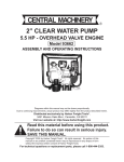
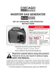
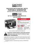
5.5 HP Lawn Mower ENGINE
96156
Installation, Operating, and Servicing
Instructions
Using an engine indoors CAN KILL YOU IN
MINUTES.
Engine exhaust contains carbon monoxide.
This is a poison you cannot see or smell.
NEVER use inside
a home or garage,
EVEN IF doors and
windows are open.
Only use OUTSIDE
and far away from
windows, doors, and
vents.
Distributed exclusively by Harbor Freight Tools®.
3491 Mission Oaks Blvd., Camarillo, CA 93011
Visit our website at: http://www.harborfreight.com
Read this material before using this product.
Failure to do so can result in serious injury.
Save this manual.
Copyright© 2008 by Harbor Freight Tools®. All rights reserved. No portion of this manual or any artwork
contained herein may be reproduced in any shape or form without the express written consent of
Harbor Freight Tools. Diagrams within this manual may not be drawn proportionally. Due to continuing
improvements, actual product may differ slightly from the product described herein. Tools required for
installation and service may not be included.
For technical questions or replacement parts, please call 1-800-444-3353.
Manual Revised 08d, 09h
Contents
Parts List��������������������������������������16
ASSEMBLY DIAGRAM���������������������17
Important SAFETY
Information���������������������������������3 LIMITED 90 DAY WARRANTY���������18
Specifications�������������������������������6 Emission Control System
Unpacking���������������������������������������6
Warranty�����������������������������������18
Installation�����������������������������������6
Operating Instructions�����������8
Engine Controls������������������������������ 8
Starting the Engine������������������������ 8
Checking and Filling Engine
Oil��������������������������������������������������� 8
Checking and Filling Fuel������� 9
Start Procedure������������������������ 9
Break-in Period������������������������� 10
Servicing��������������������������������������� 11
Maintenance Procedures�����������11
Engine Oil Change���������������������11
Air Filter Element
Maintenance�����������������������������11
Spark Plug Maintenance������� 12
Cleaning, Maintenance, and
Lubrication Schedule��������������� 12
After Initial 20 Operation
Hour Period:���������������������������� 12
Every 25 Operation Hours
Thereafter:������������������������������ 12
Every 50 Operation Hours:��� 12
Every 100 Operation Hours:� 12
Every 300 Operation Hours:� 12
Storage��������������������������������������������� 13
Troubleshooting��������������������������� 14
Page 2
For technical questions, please call 1-800-444-3353.
SKU 96156
Save This Manual
CAUTION, without the
safety alert symbol, is
used to address practices not
related to personal injury.
Keep this manual for the safety warnings
and precautions, installation, operating,
inspection, maintenance and cleaning
procedures. Write the product’s serial number
in the back of the manual near the assembly
diagram (or month and year of purchase if
product has no number). Keep this manual
and the receipt in a safe and dry place for
future reference.
WARNING! Read all instructions.
Failure to follow all instructions
listed below may result in fire,
serious injury and/or DEATH. The
warnings and precautions discussed
in this manual cannot cover all
possible conditions and situations that
may occur. It must be understood
by the operator that common sense
and caution are factors which cannot
be built into this product, but must be
supplied by the operator.
Important SAFETY
Information
In this manual, on the labeling, and
all other information provided with
this product:
This is the safety alert
symbol. It is used to alert
you to potential personal
injury hazards. Obey all
safety messages that follow
this symbol to avoid possible
injury or death.
DANGER indicates a
hazardous situation
which, if not avoided, will result
in death or serious injury.
SAVE THESE INSTRUCTIONS
Installation precautions
1.
Gasoline fuel and fumes are flammable,
and potentially explosive. Use proper
fuel storage and handling procedures.
Do not store fuel or other flammable
materials nearby.
2.
Have multiple ABC class fire
extinguishers nearby.
3.
Operation of this engine may create
sparks that can start fires around dry
vegetation.
A spark arrestor may be required.
The operator should contact local fire
agencies for laws or regulations relating
to fire prevention requirements.
4.
Install only to a lawn mower and only in
an upright position.
5.
Wear ANSI-approved safety goggles,
heavy-duty work gloves, and dust mask/
respirator during installation.
6.
Use only oil and fuel recommended
in the “Specifications” section of this
manual.
WARNING indicates a
hazardous situation
which, if not avoided, could
result in death or serious injury.
CAUTION, used with
the safety alert
symbol, indicates a hazardous
situation which, if not avoided,
could result in minor or moderate
injury.
NOTICE is used to
address practices not
related to personal injury.
SKU 96156
For technical questions, please call 1-800-444-3353.
Page 3
7.
Follow lawn mower manufacturer’s
installation procedures for attaching the
engine to the mower and connecting the
output shaft.
Operating precautions
1.
Carbon Monoxide
Hazard
Using an engine indoors
CAN KILL YOU IN MINUTES.
Engine exhaust contains
carbon monoxide. This is a poison you
cannot see or smell.
NEVER use inside a home or garage,
EVEN IF doors and windows are open.
Only use OUTSIDE and far away from
windows, doors, and vents.
2.
Keep children away from the engine,
especially while it is operating.
3.
Do not leave the engine unattended
when it is running. Turn off the engine
before leaving the work area.
4.
Wear ANSI-approved safety goggles and
hearing protection during use.
5.
People with pacemakers should
consult their physician(s) before use.
Electromagnetic fields in close proximity
to a heart pacemaker could cause
pacemaker interference or pacemaker
failure. Caution is necessary when near
the engine’s magneto or recoil starter.
Page 4
6.
Use only accessories that are
recommended by Harbor Freight Tools
for your model. Accessories that may
be suitable for one engine may become
hazardous when used on another
engine.
7.
Do not operate in explosive
atmospheres, such as in the presence
of flammable liquids, gases, or dust.
Gasoline-powered engines may ignite
the dust or fumes.
8.
Stay alert, watch what you are doing and
use common sense when operating this
engine. Do not use this engine while
tired or under the influence of drugs,
alcohol or medication.
9.
Do not overreach. Keep proper
footing and balance at all times. This
enables better control of the engine in
unexpected situations.
10. Dress properly. Do not wear loose
clothing or jewelry. Keep hair, clothing
and gloves away from moving parts.
Loose clothes, jewelry or long hair can
be caught in moving parts.
11. Parts, especially exhaust system
components, get very hot during use.
Stay clear of hot parts.
12. Do not cover the engine during
operation.
13. Keep the engine and surrounding area
clean at all times.
14. Use the engine, accessories, etc., in
accordance with these instructions and
in the manner intended for the particular
engine, taking into account the working
conditions and the work to be performed.
Use of the engine for operations different
from those intended could result in a
hazardous situation.
15. Do not operate the engine with known
leaks in the fuel system.
For technical questions, please call 1-800-444-3353.
SKU 96156
16. This product contains or, when used,
produces a chemical known to the State
of California to cause cancer and birth
defects or other reproductive harm.
(California Health & Safety Code §
25249.5, et seq.)
17. When spills of fuel or oil occur, they must
be cleaned up immediately. Dispose
of fluids and cleaning materials as per
any local, state, or federal codes and
regulations. Store oil rags in a bottomventilated, covered, metal container.
18. Keep hands and feet away from moving
parts. Do not reach over or across
engine while operating.
guards, and heat shields, among other
guards.
3.
Do not alter or adjust any part of
the engine that is sealed by the
manufacturer or distributor.
4.
Wear ANSI-approved safety goggles,
heavy-duty work gloves, and dust mask/
respirator during service.
5.
Maintain labels and nameplates on
the engine. These carry important
information. If unreadable or missing,
contact Harbor Freight Tools for a
replacement.
6.
Have the engine serviced by a qualified
repair person using only identical
replacement parts. This will ensure that
the safety of the engine is maintained.
Do not attempt any service or
maintenance procedures not explained
in this manual or any procedures that
you are uncertain about your ability to
perform safely or correctly.
The engine brake is for
emergency shutoff; do not
replace the brake spring with
a weaker spring.
7.
Store engine out of the reach of children.
8.
Follow scheduled maintenance.
19. Before use, check for misalignment
or binding of moving parts, breakage
of parts, and any other condition that
may affect the engine’s operation. If
damaged, have the engine serviced
before using. Many accidents are
caused by poorly maintained engines.
20. Use the correct engine for the
application. Do not modify the engine
and do not use the engine for a purpose
for which it is not intended. Install on
Lawn mower only.
21. Follow lawn mower manufacturer’s
operation precautions.
Service precautions
1.
Before service, maintenance, or
cleaning:
a.Close the engine’s fuel valve.
b.Allow the engine to completely cool.
c. Then, remove the spark plug wire(s)
from the spark plug(s).
2.
Keep all safety guards in place and in
proper working order. Safety guards
include muffler, air cleaner, mechanical
SKU 96156
9.
Refueling Precautions:
a.Do not smoke, or allow sparks, flames,
or other sources of ignition around the
engine, especially when refuelling.
b.Do not refill the fuel tank while the
engine is running or hot.
c. Do not fill fuel tank to the top. Leave
a little room for the fuel to expand as
needed.
d.Refuel in a well-ventilated area only.
Save these
instructions.
For technical questions, please call 1-800-444-3353.
Page 5
Specifications
Engine Rating
Type
Fuel
Capacity
Engine Oil
Installation
Read the entire Important
Safety Information
section at the beginning of this
manual including all text under
subheadings therein before
installation or use of this product.
5.5 Horsepower
89+ octane unleaded gasoline
0.45 Gallons
10W-30
Type
(Detergent or non-detergent)
Capacity
18.6 oz.
Run Time @ 50% Load 3.5 Hours with full tank
Sound Level
77 dB
4 Stroke, OHV
Engine Type
To prevent
serious injury
from accidental starting:
Close the engine’s fuel valve,
wait for the engine to cool, and
disconnect the spark plug wire(s)
before installing or making any
adjustments to the engine.
(1P68FV / 7CLGS.16368V)
Bore x Stroke
Compression Ratio
Displacement
Rotation viewed from PTO
(power takeoff - the output shaft)
Valve
Clearance
Speed
Counterclockwise
Type
7/8” x 3-1/8”, 3/16” keyway,
end tapped 3/8”-24
F6TC resistive
Gap
Intake
Exhaust
Idle
Maximum
0.028”-0.031”
0.1 mm
0.15 mm
2000 RPM
3250 RPM
Shaft Size/Type
Spark Plug
68 mm x 45 mm
8:1
163cc
To prevent
serious injury:
Operate only with proper spark
arrestor installed.
Operation of this engine may
create sparks that can start fires
around dry vegetation.
A spark arrestor may be required.
The operator should contact
local fire agencies for laws or
regulations relating to fire
prevention requirements.
(NGK® BP-6HS, Champion® RL86C)
The emission control system for this
engine is warranted for standards set by the
U.S. Environmental Protection Agency. For
warranty information, refer to the last pages of
this manual.
At high altitudes, the engine’s carburetor
and any other parts that control the fuel-air
ratio will need to be adjusted by a qualified
mechanic to allow efficient high-altitude use
and to prevent damage to the engine and any
other devices used with this product.
1.
IMPORTANT: If you have any doubts
about your ability to perform the following
procedures, have a qualified service
technician perform the installation.
2.
Install this engine on a lawn mower only.
Unpacking
When unpacking, make sure that the
item is intact and undamaged. If any parts
are missing or broken, please call Harbor
Freight Tools at 1-800-444-3353 as soon as
possible.
Page 6
Figure A - Mounting Hole Locations (Bottom View)
3.
Set the Engine upright on the mower,
and align the four 3/8” diameter coarse
threaded engine mounting holes with
For technical questions, please call 1-800-444-3353.
SKU 96156
four mower mounting holes.
(See Figure A.)
NOTE: Depending on the mower, it may
be necessary to drill mounting holes or
make a mounting plate to align with the
engine mounting holes.
4.
Use four 3/8” diameter, coarse threaded,
hardened, stainless steel Bolts, Lock
Washers, and Washers (not included) of
appropriate length to secure the Engine
to the mower.
Make sure the hardware does not
contact moving parts.
Choke
Control
Choke mower choke
bracket cable sheath
Brake
bracket
mower brake
cable sheath
6.
Automatic
Throttle Control
(not adjustable)
5.
Insert the mower’s choke cable sheath
through the hole in the Choke bracket.
Secure the mower choke cable to the
choke control. Adjust the choke cable
sheath to remove all slack and secure it
in place using the adjusting nuts on the
cable sheath. (See Figure B.)
SKU 96156
Brake
arm
FIGURE C
mower
choke
cable
FIGURE B
mower brake
cable
Insert the mower’s brake cable sheath
through the hole in the Brake bracket.
Secure the mower brake cable to the
brake arm. Adjust the brake cable
sheath to remove all slack and secure it
in place using the adjusting nuts on the
cable sheath. (See Figure C.)
The engine brake is for
emergency shutoff; do not
replace the brake spring with
a weaker spring. If operating
the engine brake is too difficult, a
qualified technician must install a
different brake handle on the mower.
Note: The brake/choke cables on some
mowers may need to be adjusted in a
different manner. Install according to
mower manufacturer’s instructions.
7.
Throttle Control - The throttle control on
this engine is controlled automatically.
Only a qualified technician should
adjust the throttle controlling
mechanism.
8.
Refer to the mower’s service manual for
instructions on how to properly attach a
belt drive pulley, chain drive gear, etc.
onto the output shaft of the Engine.
For technical questions, please call 1-800-444-3353.
Page 7
Fuel
Valve
Operating Instructions
Read the entire Important
Safety Information
section at the beginning of this
manual including all text under
subheadings therein before
installation or use of this product.
Engine Controls
Fuel Tank
Cap
Starter
Handle
Choke Control
Automatic
Throttle Control
(not adjustable)
Fuel Valve - This controls the fuel supply to
the engine.
The horizontal position is closed (off).
The vertical position is open (on).
Choke Control - This controls the air-fuel
ratio for starting the engine.
The released position is open (run).
The engaged position is closed (start).
Oil Fill
Brake
arm
Oil Fill - The oil fill cap has a dipstick
attached. The crosshatch pattern at the
bottom of the dipstick is the proper oil
range. Before each use, check that the
oil level is at the top of the cross hatched
pattern, but not above that level.
Brake Arm - This must be held back to allow
the engine to operate. It will force the
engine to stop when released.
Starter Handle - This is pulled to start the
engine.
Page 8
Automatic Throttle Control - This is
not adjustable except by a qualified
technician.
Starting the Engine
Inspect engine looking for
damaged, loose, and missing parts
before installation and starting. If
any problems are found, do not
use engine until fixed properly.
Checking and Filling Engine Oil
CAUTION! Your Warranty is VOID if the
engine’s crankcase is not properly
filled with oil before each use. Before
each use, check the oil level. Do not
run the engine with low or no engine
oil. Running the engine with no or low
engine oil WILL permanently damage the
engine.
For technical questions, please call 1-800-444-3353.
SKU 96156
1.
Clean the top of the dipstick and the area
around it. Remove the dipstick and wipe
it off with a clean rag.
2.
Reinsert the dipstick without threading
it in and remove it to check the oil level.
The oil level should be between the high
and low marks on the dipstick.
3.
If the oil level is below the low mark
add SAE 10W-30 (detergent or nondetergent) oil until the oil level is between
the high and the low marks.
4.
Replace the Oil Dipstick.
Start Procedure
Before starting the engine:
a.Follow the Installation
Instructions to prepare the
equipment.
b.Read and follow the instructions
provided with the lawn mower.
c. Inspect the equipment and
engine.
d.Fill the engine with the proper
amount and type of fuel and oil.
e.Connect the spark plug wire if it
is disconnected.
CAUTION! Do not run the engine with too
little or too much oil. The engine will be
permanently damaged.
WARNING! To prevent injury:
Do not tie down the brake
handle or otherwise override the
Checking and Filling Fuel
engine brake.
To shut off the engine,
WARNING! To prevent
release the mower’s
serious injury from fire:
Fill the fuel tank in a well-ventilated
brake handle.
area away from ignition sources.
Do not smoke.
1.
Move the lawn mower to a flat location
free of loose rocks, tall grass, sand, or
loose ground that may be thrown by the
lawnmower, or slow down the engine
while starting.
1.
To fill the Fuel Tank, first wipe off the
Fuel Tank Cap and the surrounding area.
2.
Unscrew, and remove the Fuel Tank
Cap.
2.
3.
Mix fuel stabilizer (not included) with 89
octane (or better) unleaded gasoline
according to fuel stabilizer directions.
If the lawn mower is equipped with a
transmission, put it in neutral and set the
parking brake.
3.
Open the fuel valve by turning it so it is
vertical.
4.
Then, pull and hold the choke control
cable (the closed, start position). Do not
pull the choke control if restarting a warm
engine.
5.
Squeeze the mower’s brake handle to
disengage the engine brake.
6.
Grasp the starter handle, and pull slowly
until resistance is felt. While holding the
handle, allow the starter rope to rewind
4.
Fill the Fuel Tank to about 1 inch under
the fill neck of the gasoline tank with the
stabilized unleaded gasoline mixture.
5.
Then replace the Fuel Tank Cap.
SKU 96156
For technical questions, please call 1-800-444-3353.
Page 9
slowly. Then, pull the starter handle
with a rapid, full arm stroke. Once again
while holding the handle, allow the rope
to rewind slowly. Repeat as necessary,
until the engine starts.
7.
After the engine starts and warms up,
slowly release the choke cable, allowing
it to return to its open (run) position.
8.
After each start-up, run the engine for
five minutes with no load to allow it to
stabilize.
9.
Operate the lawn mower according to
the manufacturer’s instructions.
10. After use, release the brake handle to
stop the mower.
Break-in Period
1.
Breaking-in the engine will help to ensure
proper equipment and engine operation,
and will extend the engine’s lifespan.
The warranty is void if the engine is not
broken in properly. The first 20 hours of
operation is the break-in period.
2.
During the first 3 hours of use:
• Do not apply a heavy load to the mower.
3.
After the first 20 hours of use:
• Change the engine oil.
Under normal operating conditions
subsequent maintenance follows the
schedule explained in the Servicing
section.
WARNING! If the engine does not stop
promptly when the brake handle is
released, carefully close the fuel
valve. Do not use the engine
again until the brake assembly
has been repaired by a
qualified technician.
11. To prevent accidents, turn off the engine
and disconnect its spark plug wire after
use. Wait for the engine to cool, clean
external parts with clean cloth, then store
the equipment out of children’s reach
according to the Storage instructions in
this manual.
Page 10
For technical questions, please call 1-800-444-3353.
SKU 96156
Servicing
Engine Oil Change
CAUTION! Oil is very hot during operation
and can cause burns. Wait for engine to
cool before changing oil.
To prevent
serious injury
from accidental starting:
Close the engine’s fuel valve,
wait for the engine to cool, and
disconnect the spark plug wire(s)
before performing any
inspection, maintenance, or
cleaning procedures.
To prevent
serious injury
from engine failure:
Do not use damaged engine. If
abnormal noise, vibration, or
excess smoking occurs, have the
problem corrected before further
use.
Drain
Plug
Maintenance Procedures
Many maintenance procedures,
including those not detailed in this
manual, will need to be performed
by a qualified technician for safety.
If you have any doubts about your
ability to safely service the engine,
have a qualified technician service
the engine instead.
Note: Warranty is void if proper maintenance
and servicing procedures are not
followed.
SKU 96156
1.
Place a drain pan (not included)
underneath the crankcase’s drain plug.
2.
Remove the drain plug and, if possible,
tilt the crankcase slightly to help drain
the oil out. Recycle used oil.
3.
Replace the drain plug (and gasket, if
supplied) and tighten it.
4.
Refill the oil to the proper level following
the instructions under the Starting the
Engine section.
Air Filter Element Maintenance
1.
Wipe off the air cleaner cover.
2.
The air cleaner cover is held in place by
two knobs. Remove them.
3.
Remove the air filter element.
4.
Wash the element in warm water and
mild detergent several times. Rinse.
Squeeze out excess water and allow
it to dry completely. Soak the filter in
lightweight oil briefly, then squeeze out
the excess oil.
5.
Install the new filter or the cleaned filter.
Secure the Air Cleaner Cover before
use.
For technical questions, please call 1-800-444-3353.
Page 11
Spark Plug Maintenance
1.
Disconnect spark plug wire from end
of plug. Clean out debris from around
spark plug.
2.
Using a spark plug wrench, remove the
spark plug.
3.
Inspect the spark plug:
If the electrode is oily, clean it using a
clean, dry rag.
If the electrode has deposits on it, polish
it using emery paper.
If the white insulator is cracked or
chipped, the spark plug needs to be
replaced.
4.
5.
6.
When installing a new spark plug, adjust
the plug’s gap to the specification on the
Specification chart. Do not pry against
the electrode or the insulator, the spark
plug can be damaged.
Install the new spark plug or the cleaned
spark plug into the engine. Gasket-style:
Finger-tighten until the gasket contacts
the cylinder head, then about 1/2-2/3
turn more.
Non-gasket-style: Finger-tighten until the
plug contacts the head, then about 1/16
turn more.
Apply a small amount of dielectric grease
(not included) to the insulator of the
spark plug and attach the wire securely
to the spark plug.
Cleaning, Maintenance, and
Lubrication Schedule
Note: This maintenance schedule is
intended solely as a general guide. If
performance decreases or if engine
operates unusually, check systems
immediately. The maintenance needs
of each engine will differ depending on
factors such as duty cycle, temperature,
air quality, fuel quality, and other factors.
Note: These procedures are in addition to
the regular checks and maintenance
explained as part of the regular operation
of the engine.
After Initial 20 Operation Hour Period:
a.Change engine oil.
Every 25 Operation Hours Thereafter:
a.Clean/replace air filter element.
b.Inspect/clean spark plug.
Every 50 Operation Hours:
a.Change engine oil.
Every 100 Operation Hours:
a.Replace spark plug.
b.Replace air filter element.
Note: All maintenance procedures scheduled
for 25, 50, and 100 operation hours
should be performed at least yearly.
Every 300 Operation Hours:
a.Clean fuel tank and carburetor.
b.Clean carbon build-up from combustion
chamber.
Page 12
For technical questions, please call 1-800-444-3353.
SKU 96156
Storage
1.
Wait for engine to cool, then clean
engine with clean cloth.
2.
When the engine is to remain idle for
longer than 20 days, prepare the engine
for storage as follows:
a.Change engine oil and empty fuel tank.
b.Either leave fuel tank empty or refill
fuel tank with fresh unleaded gasoline
mixed with a fuel stabilizer intended for
long term engine storage (not included).
After filling, run engine for about 5-10
minutes to circulate the treated gasoline
through the carburetor. Wait for engine
to cool before proceeding.
c. Clean out area around spark plug.
Remove spark plug and pour one
tablespoon of engine oil into cylinder
through spark plug hole.
d.Reinstall spark plug, but leave spark
plug wire disconnected.
e.Pull recoil starter to distribute oil
in cylinder. Stop after one or two
revolutions when you feel the piston
start the compression stroke (when you
start to feel resistance).
3.
Apply a thin coat of rust preventive oil to
all uncoated metal parts.
4.
Cover and store in a dry, well-ventilated
area out of reach of children.
5.
Before starting the engine after storage,
keep in mind that untreated gasoline
will deteriorate quickly. Drain the fuel
tank and filter, and change to fresh fuel
if untreated gasoline has been sitting
for a month, if treated gasoline has
been sitting beyond the fuel stabilizer’s
recommended time period, or if the
engine does not start properly.
SKU 96156
For technical questions, please call 1-800-444-3353.
Page 13
Troubleshooting
Engine will not
start
Mower ENGINE Specific:
1. Brake Handle not held or brake
cable not connected properly.
2. Mower on top of grass.
Mower ENGINE Specific:
1. Make sure brake handle is held down and
brake cable is properly adjusted.
2. Start mower atop clear area free of loose
objects and grass.
Fuel Related:
Fuel Related:
1. No fuel in tank or fuel valve closed. 1. Fill fuel tank and open fuel valve.
2. Choke not in start position,
2. Move choke to start position if engine is
especially with cold engine.
cold.
3. Low quality or deteriorated, old
3. Use only fresh 89+ octane unleaded
gasoline.
gasoline.
4. Carburetor not primed.
4. Prime carburetor by pressing priming bulb
specified number of times (if equipped).
5. Dirty fuel passageways blocking fuel 5. Clean out passageways using fuel additive.
flow.
Heavy deposits may require further
cleaning.
6. Carburetor needle stuck. Fuel can
6. Gently tap side of carburetor float chamber
be smelled in the air.
with screwdriver handle.
7. Too much fuel in chamber. This can 7. Turn choke to run position. Remove spark
be caused by the carburetor needle
plug and pull the start handle several times
sticking.
to air out the chamber. Reinstall spark plug
and set choke to start position.
Ignition (spark) Related:
Ignition (spark) Related:
1. Spark plug wire not connected
1. Connect spark plug wire properly.
securely.
2. Spark plug electrode wet or dirty.
2. Clean spark plug.
3. Incorrect spark plug gap.
3. Correct spark plug gap.
4. Spark plug wire or spark plug
4. Replace spark plug wire and/or spark plug.
broken.
5. Incorrect spark timing or faulty
5. Have qualified technician diagnose/repair
ignition system.
ignition system.
Compression Related:
Compression Related:
1. Cylinder not lubricated. Problem
1. Pour tablespoon of oil into spark plug hole.
after long storage periods.
Crank engine a few times and try to start
again.
2. Loose or broken spark plug.
2. Tighten spark plug. If that does not work,
(Hissing noise will occur when trying
replace spark plug. If problem persists, may
to start.)
have head gasket problem, see #3.
3. Loose cylinder head or damaged
3. Tighten head. If that does not remedy
head gasket. (Hissing noise will
problem, replace head gasket.
occur when trying to start.)
4. Engine valves or tappets
4. Adjust valve clearance. If that does not
misadjusted or stuck.
work, clean or replace valves/tappets.
Follow all safety precautions whenever diagnosing or
servicing the engine.
Page 14
For technical questions, please call 1-800-444-3353.
SKU 96156
Problem
Engine misfires
Possible Causes
1. Spark plug wire loose.
2. Incorrect spark plug gap or
damaged spark plug.
3. Defective spark plug wire.
4. Old or low quality gasoline.
5. Incorrect compression.
Engine stops
suddenly
1. Low oil shutdown.
Engine knocks
2. Fuel tank empty or full of impure or
low quality gasoline.
3. Defective fuel tank cap creating
vacuum, preventing proper fuel flow.
4. Improper idle speed.
5. Brake cable broken.
6. Faulty magneto, incorrect timing, or
clogged carburetor.
1. Old or low quality gasoline.
Engine backfires
2. Engine overloaded.
3. Incorrect spark timing, deposit
buildup, worn engine, or other
mechanical problems.
1. Impure or low quality gasoline.
Probable Solutions
1. Check wire connections.
2. Re-gap or replace spark plug.
3. Replace spark plug wire.
4. Use only fresh 89+ octane unleaded
gasoline.
5. Diagnose and repair compression. (Use
Engine will not start: Compression
Related section.)
1. Fill engine oil to proper level. Check engine
oil before EVERY use.
2. Fill fuel tank with fresh 89+ octane unleaded
gasoline.
3. Test/replace fuel tank cap.
4. Properly adjust idle speed.
5. Repair brake cable as needed.
6. Have qualified technician diagnose and
service engine.
1. Fill fuel tank with fresh 89+ octane unleaded
gasoline.
2. Do not exceed engine’s load rating.
3. Have qualified technician diagnose and
service engine.
1. Fill fuel tank with fresh 89+ octane unleaded
gasoline.
2. Engine too cold.
2. Use cold weather fuel and oil additives to
prevent backfiring.
3. Choke not open after engine warm. 3. Move choke to run position after engine
warms up.
4. Engine not properly adjusted for
4. Qualified technician must adjust engine at
high altitude operation.
altitudes greater than 5,000 feet above sea
level.
5. Intake valve stuck, choke stuck,
5. Have qualified technician diagnose and
incorrect timing, clogged carburetor,
service engine.
or overheated engine.
Follow all safety precautions whenever diagnosing or
servicing the engine.
SKU 96156
For technical questions, please call 1-800-444-3353.
Page 15
Parts List
Part
1
2
3
4
5
6
7
8
9
10
11
12
13
14
15
16
17
18
19
20
21
22
23
24
25
26
27
28
29
30
31
32
33
34
35
36
37
38
39
40
41
42
43
44
45
45a
46
47
Description
Starting flange
Fuel pipe
Air duck
Fuel cock
Crankcase
Set pin Ø9×14
Gasket, crankcase
Sump, crankcase B
Cylinder head asm
Gasket, cylinder head
Exhaust gasket
Cylinder head cover
Gasket, cylinder head cover
Piston
Piston ring set
Carburetor C
Stud
Muffler
Muffler hood
Driven gear, regulator
Clamp, regulating shaft
Regulating arm asm
Back spring
Flywheel
Regulating mount C
Fuel filler cap asm
Fuel filler cap
Air cleaner housing
Foam ,air cleaner
Air cleaner cover
Air cleaner bolt
Gasket, inlet
Crankshaft set
Connecting rod
Pusher
Valve piece
Crankshaft Filter-cover
Crankshaft Filter-Gasket
Crankshaft Filter-Gasket
Heat insulator
Gasket, carburetor
Stud
Pulling rod
Oil seal Ø25×40×7
Brake asm.
Brake Spring
Fine regulating spring
Stud
Q’ty
1
1
1
1
1
2
1
1
1
1
1
1
1
1
1
1
1
1
1
1
1
1
1
1
1
1
1
1
1
1
2
1
1
1
2
1
1
1
1
1
1
1
1
1
1
1
1
1
Record Product’s Serial Number Here:
Part
48
49
50
51
52
53
54
55
56
57
58
59
60
61
62
63
64
65
66
67
68
69
70
71
72
73
74
75
76
77
78
79
80
81
82
83
84
85
86
88
89
90
91
92
93
94
95
96
Description
Q’ty
Stud
Stud
Bolt
Gauze
Dipstick
Filler
Gasket, air cleaner
Regulating sway bar
Split pin
Oil seal Ø6×11×5
Washer
Nut
Ignition coil
Sleeve
Upper oil seal Ø25×38×7
Choke link
Drain plug
Washer
Set pin Ø10×16
Piston pin
Piston pin circlip
Camshaft
Pusher guide
Adjusting bolt for valve gap
Valve rocker
Sleeve
Lock nut
Tappet
Intake valve
Exhaust valve
Spring seat, intake valve
Valve spring
Spring seat, exhaust valve
Cap
Lock bolt
Spark plug F6TC
Bearing 6205
Bolt M6×12
Bolt M6×20
Bolt M6×32
Bolt M8×50
Nut M6
Nut M6
Nut M6
Starter hood
Pipe clamp with thread
Adjusting washer
Self-locking nut M6
2
2
4
1
1
1
1
1
1
1
1
1
1
4
1
1
1
1
2
1
2
1
1
2
2
2
2
2
1
1
1
2
1
1
1
1
1
9
2
4
6
2
1
3
1
4
1
2
Note: If product has no serial number, record month and year of purchase instead.
Note: Some parts are listed and shown for illustration purposes only, and are not available
individually as replacement parts.
REV 08b
Page 16
For technical questions, please call 1-800-444-3353.
SKU 96156
ASSEMBLY DIAGRAM
45a
REV 08b
SKU 96156
For technical questions, please call 1-800-444-3353.
Page 17
PLEASE READ THE FOLLOWING
CAREFULLY
The manufacturer and/or distributor
has provided the parts list and assembly
diagram in this manual as a reference
tool only. Neither the manufacturer or
distributor makes any representation
or warranty of any kind to the buyer
that he or she is qualified to make any
repairs to the product, or that he or she
is qualified to replace any parts of the
product. In fact, the manufacturer and/
or distributor expressly states that all
repairs and parts replacements should
be undertaken by certified and licensed
technicians, and not by the buyer. The
buyer assumes all risk and liability arising
out of his or her repairs to the original
product or replacement parts thereto,
or arising out of his or her installation
of replacement parts thereto.
LIMITED 90 DAY WARRANTY
Harbor Freight Tools Co. makes every
effort to assure that its products meet
high quality and durability standards, and
warrants to the original purchaser that this
product is free from defects in materials and
workmanship for the period of 90 days from
the date of purchase. This warranty does not
apply to damage due directly or indirectly,
to misuse, abuse, negligence or accidents,
repairs or alterations outside our facilities,
criminal activity, improper installation, normal
wear and tear, or to lack of maintenance. We
shall in no event be liable for death, injuries
to persons or property, or for incidental,
contingent, special or consequential damages
arising from the use of our product. Some
states do not allow the exclusion or limitation
of incidental or consequential damages,
so the above limitation of exclusion may
not apply to you. This warranty is
expressly in lieu of all other
warranties, express or implied,
including the warranties of
merchantability and fitness.
Page 18
To take advantage of this warranty,
the product or part must be returned to us
with transportation charges prepaid. Proof
of purchase date and an explanation of the
complaint must accompany the merchandise.
If our inspection verifies the defect, we
will either repair or replace the product at
our election or we may elect to refund the
purchase price if we cannot readily and
quickly provide you with a replacement. We
will return repaired products at our expense,
but if we determine there is no defect, or that
the defect resulted from causes not within the
scope of our warranty, then you must bear the
cost of returning the product.
This warranty gives you specific legal
rights and you may also have other rights
which vary from state to state.
3491 Mission Oaks Blvd. • PO Box 6009 •
Camarillo, CA 93011 • (800) 444-3353
Emission Control System
Warranty
United States Emission Control Defects Warranty
Statement
The United States Environmental Protection Agency (herein
EPA) and Harbor Freight Tools (herein HFT) are pleased to explain the
emission control system warranty on your 1997 and later Small OffRoad Engine (herein engine). Within the United States, new off-road,
spark-ignition engines certified for model year 1997 and later, must be
designed, built and equipped to meet the stringent anti-smog standards
set forth by the EPA. HFT must warrant the emission control system on
your engine for the periods of time described below, provided there has
been no abuse, neglect or improper maintenance of your engine.
Your emission control system may include parts such as the carburetor or fuel-injection system, and the ignition system. Also included may
be hoses, belts, connectors and other emission-related assemblies.
Where a warrantable condition exists, HFT will repair your engine
at no cost to you including diagnosis, parts and labor.
Manufacturer’s Warranty Coverage
The 1997 and later engines are warranted for two (2) years. If
any emission-related part on your engine is defective, the part will be
repaired or replaced by HFT.
Harbor Freight Tools Emission Control Defects
Warranty Coverage
Engines are warranted for a period of two (2) years relative to
emission control parts defects, subject to the provisions set forth below.
For technical questions, please call 1-800-444-3353.
SKU 96156
If any emission related part on your engine is defective, the part will be
repaired or replaced by HFT.
Owner’s Warranty Responsibilities
• As the engine owner, you are responsible for the performance
of the required maintenance listed in your Owner’s Manual. HFT
recommends that you retain all receipts covering maintenance
on your engine, but HFT cannot deny warranty solely for the lack
of receipts or for your failure to ensure the performance of all
scheduled maintenance.
• As the engine owner, you should, however, be aware that HFT
may deny you warranty coverage if your engine or a part has
failed due to abuse, neglect, improper maintenance, or unapproved modifications.
• You are responsible for shipping your engine to a HFT warranty
station as soon as a problem exists. Contact the HFT Customer
Service department at the number below to make shipping arrangements. The warranty repairs should be completed in a reasonable
amount of time, not to exceed 30 days.
If you have any questions regarding your warranty rights and
responsibilities, you should contact the Harbor Freight Tools Customer
Service Department at 1-800-444-3353.
Harbor Freight Tools Emission Control Defects
Warranty Provisions
1. Length of Coverage
HFT warrants to a first retail purchaser and each subsequent
purchaser that the engine is free from defects in materials and
workmanship that cause the failure of warranted parts for a
period of two (2) years after the date of delivery to the first retail
purchaser.
2.No Charge Repair or Replacement
Repair or replacement of any warranted part will be performed at
no charge to the owner if the work is performed through a warranty
station authorized by HFT. For emissions warranty service, contact
the HFT Customer Service Department at 1-800-444-3353.
5.Service and Maintenance
Component parts which are not scheduled for replacement as
required maintenance or are scheduled only for regular inspection
to the effect of “repair or replace as necessary” are warranted for
the warranty period. Any warranted part which is scheduled for
replacement as required maintenance is warranted for the period
of time up to the first scheduled replacement point for that part.
Any replacement part, provided it is equivalent in durability and
performance, may be used in performance of maintenance or
repairs. The owner is responsible for commissioning a qualified
technician/mechanic to perform all required maintenance, as
outlined in the Inspection, Cleaning, and Maintenance section in
this manual.
6.Warranted Parts
1)
Fuel Metering System
i) Carburetor and its internal parts.
ii) Fuel pump (if so equipped).
iii) Cold start enrichment system.
2)Air Induction System
i) Intake pipe/manifold.
ii) Air cleaner.
3) Ignition System
i) Spark plug.
ii) Magneto ignition system.
4)Catalyst System (if so equipped)
i) Exhaust pipe stud.
ii) Muffler.
iii) Catalytic converter (if so equipped).
5) Miscellaneous Items Used in Above Systems
i) Vacuum, temperature and time sensitive valves and
switches.
ii) Hoses, belts, connectors, and assemblies.
3.Consequential Damages Coverage
Coverage under this warranty shall also extend to the failure of
any engine components caused by the failure of any warranted
part while it is still covered under this warranty.
4.Coverage Exclusions
Warranty claims shall be filed in accordance with the provisions
of the HFT warranty policy explained in the box at the top of the
previous page. HFT shall not be liable for any loss of use of the
engine, for any alternative usage, for any damage to goods, loss of
time, or inconvenience. Warranty coverage shall also be excluded
for any part which fails, malfunctions, or is damaged due to failure
to follow the maintenance and operating instructions set forth in
the Owner’s Manual including, but not limited to:
a) Use of parts which are not authorized by HFT
b) Improper installation, adjustment or repair of the engine or
of any warranted part unless performed by an authorized
warranty center
c) Failure to follow recommendations on fuel use contained in
the Owner’s Manual
d) Improper or inadequate maintenance of any warranted
parts
e) Repairs performed outside of the authorized warranty service
dealers
f) Alterations by changing, adding to or removing parts from
the engine.
SKU 96156
For technical questions, please call 1-800-444-3353.
Page 19