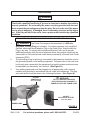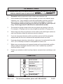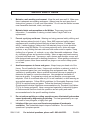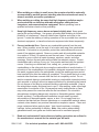
1
MIG WELDER - 250 AMP
Model 91146
ASSEMBLY AND OPERATING INSTRUCTIONS
®
3491 Mission Oaks Blvd., Camarillo, CA 93011
Visit our Web site at: http://www.harborfreight.com
Copyright© 2005 by Harbor Freight Tools®. All rights reserved. No portion of this
manual or any artwork contained herein may be reproduced in any shape or form
without the express written consent of Harbor Freight Tools.
For technical questions, please call 1-800-444-3353.
PRODUCT SPECIFICATIONS
Item
Electrical Requirements
Duty Cycles
Maximum Welding
Thickness Capacity
Welding Current
Required Wire Sizes
Wire Control Settings
Gun Coolant Type
Fuse Type
Gun Power Cable Length
Ground Clamp Cable Length
Wheels
Accessories
Weight
Description
Input Voltage: 220V / 60 Hz / 45 Input Amperage
Power Cord: 10 AWG @ 6’ Long
Power Plug: 220V (not included), Requires 50 Amp Circuit
60% @ 250 Amps / 100% @ 195 Amps
Up To 3/8” Mild Steel
30 – 250 Amps
.024” To .047” Diameter
Internal, Spot & Pause, 4 Time, & 2 Time
Air Cooled
3 AMP Buss Fuse
13’
13’
Front: Swivel Castors / 3-1/4” Diameter x 1” Thick
Rear: Rigid / 8” Diameter x 1-1/2” Thick on 7/8” Diameter Axle
Gas Pressure Regulator w/Flow Meter
Welding Gloves / Face Mask / 1 Torch Liner / 5 Spare Tips
187 Pounds
SAVE THIS MANUAL
You will need this manual for the safety warnings and precautions, assembly, operating,
inspection, maintenance and cleaning procedures, parts list and assembly diagram.
Keep your invoice with this manual. Write the invoice number on the inside of the front
cover. Keep this manual and invoice in a safe and dry place for future reference.
UNPACKING
When unpacking, check to make sure all the parts shown on the Parts Lists on pages 26
and 27 are included. If any parts are missing or broken, please call Harbor Freight Tools
at the number shown on the cover of this manual as soon as possible.
GENERAL SAFETY RULES
WARNING!
READ AND UNDERSTAND ALL INSTRUCTIONS
Failure to follow all instructions listed below may result in
electric shock, fire, and/or serious injury.
SAVE THESE INSTRUCTIONS
WORK AREA
1.
Keep your work area clean and well lit. Cluttered benches and dark areas
invite accidents.
2.
Do not operate welding equipment in explosive atmospheres, such as in
the presence of flammable liquids, gases, or dust. Welding equipment
creates sparks which may ignite the dust or fumes.
SKU 91146
For technical questions, please call 1-800-444-3353.
PAGE 2
3.
Keep bystanders, children, and visitors away while operating welding
equipment. Distractions can cause you to lose control. Protect others in the
work area from arc rays, sparks, and slag. Provide barriers or shields as
needed.
ELECTRICAL SAFETY
1.
Grounded welding equipment must be plugged into an outlet properly
installed and grounded in accordance with all codes and ordinances.
Never remove the grounding prong or modify the plug in any way. Do not
use any adapter plugs. Check with a qualified electrician if you are in
doubt as to whether the outlet is properly grounded. If the welding equipment
should electrically malfunction or break down, grounding provides a low
resistance path to carry electricity away from the user.
2.
Avoid body contact with grounded surfaces such as pipes, radiators,
ranges, and refrigerators. There is an increased risk of electric shock if your
body is grounded.
3.
Do not expose welding equipment to rain or wet conditions. Water entering
welding equipment will increase the risk of electric shock.
4.
Do not abuse the Power Cord. Never use the Power Cord to carry welding
equipment or pull the Plug from an outlet. Keep the Power Cord away from
heat, oil, sharp edges, or moving parts. Replace damaged Power Cords
immediately. Damaged Power Cords increase the risk of electric shock.
5.
When operating welding equipment outside, use an outdoor extension cord
marked “W-A” or “W”. These extension cords are rated for outdoor use, and
reduce the risk of electric shock.
The minimum extension cord size for this tool is 6 GAUGE for cords UP TO 25’ LONG.
CORDS LONGER THAN 25’ SHOULD NOT BE USED WITH THE WELDER.
PERSONAL SAFETY
1.
Stay alert. Watch what you are doing, and use common sense when
operating welding equipment. Do not use welding equipment while tired or
under the influence of drugs, alcohol, or medication. A moment of inattention
while operating welding equipment may result in serious personal injury.
SKU 91146
For technical questions, please call 1-800-444-3353.
PAGE 3
2.
Dress properly. Do not wear loose clothing or jewelry. Contain long hair.
Keep your hair, clothing, and gloves away from hot or moving parts. Loose
clothes, jewelry, or long hair can be caught in hot or moving parts.
(See page 8, number 3, for recommended safety clothing.)
3.
Avoid accidental starting. Be sure the Power Switch is off before plugging
in. Plugging in welding equipment with the Power Switch on invites accidents.
4.
Remove adjusting keys or wrenches before turning on the welding
equipment. A wrench or a key that is left attached to an electrically charged part
of the welding equipment may result in personal injury.
5.
Do not overreach. Keep proper footing and balance at all times. Proper
footing and balance enables better control of the welding equipment in
unexpected situations.
TOOL USE AND CARE
1.
Use clamps (not included) or other practical ways to secure and support
the workpiece to a stable platform. Holding the work by hand or against your
body is unstable and may lead to loss of control.
2.
Do not force the welding equipment. Use the correct equipment for your
application. The correct equipment will do the job better and safer at the rate for
which it is designed.
3.
Do not use the power tool if the Power Switch does not turn it on or off.
Any equipment that cannot be controlled with the Power Switch is dangerous and
must be replaced.
4.
Disconnect the Power Cord Plug from the power source before making any
adjustments, changing accessories, or storing the welding equipment.
Such preventive safety measures reduce the risk of starting the welding
equipment accidentally.
5.
Store idle welding equipment out of reach of children and other untrained
persons. Welding equipment is dangerous in the hands of untrained users.
6.
Maintain welding equipment with care. Keep equipment clean and dry.
Properly maintained equipment is less likely to malfunction and is easier to
control. Do not use damaged welding equipment. Tag damaged equipment “Do
not use” until repaired.
7.
Check for misalignment or binding of moving parts, breakage of parts, and
any other condition that may affect the equipment’s operation. If damaged,
have the equipment serviced before using. Many accidents are caused by
poorly maintained equipment.
SKU 91146
For technical questions, please call 1-800-444-3353.
PAGE 4
8.
Use only accessories that are recommended by the manufacturer for your
model. Accessories that may be suitable for one type of welding equipment may
become hazardous when used on another type of equipment
SERVICE
1.
Equipment service must be performed only by qualified repair personnel.
Service or maintenance performed by unqualified personnel could result in a risk
of injury.
2.
When servicing welding equipment, use only identical replacement parts.
Follow instructions in the “Inspection, Maintenance, And Cleaning” section
of this manual. Use of unauthorized parts or failure to follow maintenance
instructions may create a risk of electric shock, burns, or other injury.
SKU 91146
For technical questions, please call 1-800-444-3353.
PAGE 5
GROUNDING
WARNING!
Improperly connecting the grounding wire can result in the risk of electric shock.
Check with a qualified electrician if you are in doubt as to whether the outlet is
properly grounded. Do not modify the power cord plug provided with the tool.
Never remove the grounding prong from the plug. Do not use the tool if the power
cord or plug is damaged. If damaged, have it repaired by a service facility before
use. If the plug will not fit the outlet, have a proper outlet installed by a qualified
electrician.
GROUNDED EQUIPMENT: EQUIPMENT WITH THREE PRONG PLUGS
1.
2.
3.
WARNING! The Power Cord requires the attachment of a 220 volt,
grounded, 3-Prong Plug (not included). For safety purposes, only a qualified,
certified, electrician should attach a Plug to the Power Cord. Never modify the
Plug in any way. To comply with the National Electric Code, and to provide
additional protection from the risk of electrical shock, this product should only be
connected to a 220 volt electrical outlet that is protected by a Ground Fault Circuit
Interrupter (GFCI).
The grounding prong in the plug is connected to the green wire inside the cord to
the grounding system in the welding equipment. The green wire in the cord must
be the only wire connected to the equipment’s grounding system and must never
be attached to an electrically “live” terminal. (See Figure A.)
Your welding equipment must be plugged into an appropriate outlet, properly
installed and grounded in accordance with all codes and ordinances. The plug
and outlet should look like those in the following illustration. (See Figure A.)
220 VOLT
POWER PLUG
(NOT INCLUDED)
WARNING!
ONLY A QUALIFIED, CERTIFIED
ELECTRICIAN SHOULD CONNECT A
POWER PLUG TO THE POWER CORD.
220 VOLT
ELECTRICAL OUTLET
(NOT INCLUDED)
POWER CORD
FIGURE A
SKU 91146
For technical questions, please call 1-800-444-3353.
PAGE 6
EXTENSION CORDS
The minimum extension cord size for this tool is 6 GAUGE for cords UP TO 25’ LONG.
CORDS LONGER THAN 25’ SHOULD NOT BE USED WITH THIS WELDER.
1.
Grounded welding equipment require a three wire extension cord.
2.
As the distance from the supply outlet increases, you must use a heavier gauge
extension cord. Using extension cords with inadequately sized wire causes a
serious drop in voltage, resulting in loss of power and possible tool damage.
The minimum extension cord gauge for this tool is 6 AWG for cords up to 25’
long. Cords longer than 25’ should not be used with this welder.
3.
The smaller the gauge number of the wire, the greater the capacity of the cord.
For example, a 14 gauge cord can carry a higher current than a 16 gauge cord.
4.
When using more than one extension cord to make up the total length, make sure
each cord contains at least the minimum wire size required.
5.
If you are using one extension cord for more than one tool, add the nameplate
amperes and use the sum to determine the required minimum cord size.
6.
If you are using an extension cord outdoors, make sure it is marked with the suffix
“W-A” (“W” in Canada) to indicate it is acceptable for outdoor use.
7.
Make sure your extension cord is properly wired and in good electrical condition.
Always replace a damaged extension cord or have it repaired by a qualified
electrician before using it.
8.
Protect your extension cords from sharp objects, excessive heat, and damp or wet
areas.
SYMBOLOGY
Double Insulated
Canadian Standards
Association
Underwriters
Laboratories, Inc.
V~
A
FIGURE C
SKU 91146
no
Volts Alternating Current
Amperes
No Load Revolutions
xxxx/min. per Minute (RPM)
For technical questions, please call 1-800-444-3353.
PAGE 7
SPECIFIC SAFETY RULES
1.
Maintain a safe working environment. Keep the work area well lit. Make sure
there is adequate surrounding workspace. Always keep the work area free of
obstructions, grease, oil, trash, and other debris. Do not use the Welder in areas
near flammable chemicals, dusts, and vapors.
2.
Maintain labels and nameplates on the Welder. These carry important
information. If unreadable or missing, contact Harbor Freight Tools for a
replacement.
3.
Prevent eye injury and burns. Wearing and using personal safety clothing and
safety devices reduce the risk of injury. Wear ANSI approved safety impact
eyeglasses with a welding helmet featuring at least a number 10 shade lens
rating. Leather leggings, rubber soled, fire resistant shoes or boots should be
worn when using this Welder. Do not wear pants with cuffs, shirts with open
pockets, or any clothing that can catch and hold molten metal or sparks. Keep
clothing free of grease, oil, solvents, or any other flammable substances. Wear
dry, insulating gloves and protective clothing. Wear an approved head covering
to protect head and neck. Use aprons, cape, sleeves and shoulder covers, and
bibs designed and approved for welding procedures. When welding overhead or
in confined spaces, wear flame resistant ear plugs or ear muffs to keep sparks
out of ears.
4.
Avoid overexposure to fumes and gases. Always keep your head out of the
fumes. Do not breathe the fumes. Use enough ventilation or exhaust, or both, to
keep fumes and gases from your breathing zone and general area. Where
ventilation is questionable, have a qualified technician take an air sampling to
determine the need for corrective measures. Use mechanical ventilation to
improve air quality. If engineering controls are not feasible, use an approved
respirator. Work in a confined area only if it is well ventilated, or while wearing an
air-supplied respirator. Follow OSHA guidelines for Permissible Exposure Limits
(PEL’s) for various fumes and gases. Follow the American Conference of
Governmental Industrial Hygienists recommendations for Threshold Limit Values
(TLV’s) for fumes and gases. Have a recognized specialist in Industrial Hygiene
or Environmental Services check the operation and air quality and make
recommendations for the specific welding situation.
5.
Do not perform welding or cutting operations near chlorinated hydrocarbon
vapors produced by degreasing or painting. The heat generated by arc rays
can react to form phosgene, a highly toxic gas.
6.
Irritation of the eyes, nose, and throat are symptoms of inadequate
ventilation. Take immediate steps to improve ventilation. Do not continue
operations if symptoms persist.
SKU 91146
For technical questions, please call 1-800-444-3353.
PAGE 8
7.
When welding or cutting in small areas, the operator should be externally
accompanied by another person (standing near the enclosed work area) to
observe accident prevention procedures.
8.
When welding or cutting, be aware that high frequency radiation may be
produced which can interfere with radio navigation, safety devices,
computers, and communications equipment. Before operating, have a
qualified technician check out that possibility.
9.
Keep high frequency source doors and panels tightly shut. Keep spark
gaps at the correct settings. Use proper grounding and shielding to minimize the
possibility of interference. Keep all cables close together and close to the
ground. Locate the welding or cutting operation as far as possible from sensitive
electronic equipment, or have the electronic equipment shut down temporarily.
10.
Prevent accidental fires. Remove any combustible material from the work
area. When possible, move the work to a location well away from combustible
materials. If relocation is not possible, protect the combustibles with a cover
made of fire resistant material. Remove or make safe all combustible materials
for a radius of 35 feet (10 meters) around the work area. Use a fire resistant
material to cover or block all open doorways, windows, cracks, and other
openings. Enclose the work area with portable fire resistant screens. Protect
combustible walls, ceilings, floors, etc., from sparks and heat with fire resistant
covers. If working on a metal wall, floor, ceiling, etc., prevent ignition of
combustibles on the other side by moving the combustibles to a safe location. If
relocation of the combustibles is not possible, designate someone to serve as a
fire watch, equipped with a fire extinguisher, during the welding process and at
least one half hour after the welding is completed. Do not place the torch on any
material other than bare concrete until the torch is completely cooled. Do not
weld on materials having a combustible coating or combustible internal structure
such as walls or ceilings, without an approved method for eliminating the hazard.
Do not dispose of hot slag in containers holding combustible materials. Keep a
fire extinguisher nearby, and know how to use it. After welding, make a thorough
examination for evidence of fire. Be aware that easily visible smoke or flame
may not be present for some time after the fire has started. Do not weld in
atmospheres containing dangerously reactive or flammable gasses, vapors,
liquids, and dust. Provide adequate ventilation in work areas to prevent
accumulation of flammable gases, vapors, or dust. Do not apply heat to a
container that has held an unknown substance or a combustible material whose
contents, when heated, can produce flammable or explosive vapors. Clean and
purge containers before applying heat. Vent closed containers, including
castings, before preheating or welding. Note: Use caution when welding
galvanized metal; toxic gases are formed and must be ventilated properly.
11.
Read and understand all instructions and safety precautions as outlined in
the manufacturer’s manual for the material you will weld.
SKU 91146
For technical questions, please call 1-800-444-3353.
PAGE 9
12.
Industrial applications must follow OSHA requirements.
13.
Never plug the Power Cord of this product into an electrical outlet while
standing on a wet or damp surface.
14.
Connect the earth ground as near as possible to the operating area. Earth
connections to structural parts of the building or other places distant to the
operating area will reduce their effectiveness and increase the danger of electric
shock.
15.
In addition to grounding the workpiece with the Welder Grounding Clamp, an
earth grounding of the workpiece is recommended. Ground it directly to an
earth pipe or grounding rod with a separate cable of appropriate size.
IMPORTANT: Only a qualified, certified electrician should perform this
procedure.
16.
Do not touch the welding wire if you are in contact with the workpiece,
ground, or another welding wire from a different machine.
17.
Do not allow the welding wire to touch earth ground. Accidental earth
discharges may cause overheating and fire hazards.
18.
Do not pass equipment cables through or near lifting chains, crane cables,
or any electrical lines.
19.
Never use the Welder near water. Ensure that the surrounding area and cutting
objects are dry. Do not spray water or other liquids on or near the Welder.
20.
Avoid all direct contact between the skin and wet garments and metal parts
under electrical power. Check that gloves and protective clothing are dry.
21.
Never leave the Welder unattended when it is plugged into an electrical
outlet. Make sure to unplug it from its electrical outlet before leaving the area.
22.
Do not unplug the Welder by pulling on the Power Cord. Keep the Power
Cord away from heated surfaces.
23.
Always turn off the Welder in the event of a power failure.
24.
Significant DC electrical voltage exists after turning off and unplugging the
Welder. Discharge the electrode to ground before handling.
SKU 91146
For technical questions, please call 1-800-444-3353.
PAGE 10
25.
Performance of this Welder may vary depending on variations in local line
voltage. Extension cord usage may also affect tool performance.
26.
Always turn off the Welder and unplug the unit from its electrical outlet
before performing any inspection, maintenance, or cleaning procedures.
27.
Use the right tool or attachment for the right job. Do not attempt to force a
small tool or attachment to do the work of a larger industrial tool or attachment.
There are certain applications for which this product was designed. It will do the
job better and more safely at the rate for which it was intended. Do not modify
this product, and do not use this product for a purpose for which it was not
intended.
28.
Proper cylinder care: Secure cylinders to the Base of the Welder, a wall, or
post to prevent them from falling. All cylinders should be used and stored in an
upright position in a well ventilated area. Never drop or strike a cylinder. Do not
use cylinders that have been dented. Cylinder caps should be used when
moving or storing cylinders. Empty cylinders should be kept in specified areas
and clearly marked “empty”. Never use oil or grease on any inlet connector, outlet
connector, or cylinder valve. Additional specific instructions for the safe handling
of cylinders should be supplied by your cylinder supplier and covered under local,
state, and federal regulations governing pressurized gases.
29.
WARNING! The brass components of this product contain lead, a chemical
known to the State of California to cause birth defects (or other reproductive
harm). (California Health & Safety code 25249.5, et seq.)
30.
WARNING! This product, when used for welding, cutting, and similar
applications, produces chemicals known to the State of California to cause cancer
and birth defects (or other reproductive harm). (California Health & Safety code
25249.5, et seq.)
31.
WARNING! People with pacemakers should consult with their physician(s)
before using this product. Operation of electrical equipment in close proximity to
a heart pacemaker could cause interference or failure of the pacemaker.
32.
WARNING! The warnings, precautions, and instructions discussed in this
instruction manual cannot cover all possible conditions and situations that may
occur. It must be understood by the operator that common sense and caution
are factors which cannot be built into this product, but must be supplied by the
operator.
SKU 91146
For technical questions, please call 1-800-444-3353.
PAGE 11
PRODUCT OVERVIEW
1.
This Welder is designed for MIG/MAG welding on mild steel, stainless steel, and
nonferrous materials up to 3/8” thickness. Additional features of this unit are as
follows: (See Figure D.)
A. Constant voltage transformer with step-up adjustment.
B. Digital step-less electronic speed control.
C. 2/4 Times, interval, and spot/pause welding.
D. Pre-gas and post-gas flow.
E. Soft start, burnback.
F. Real-time digital volt-amp meter.
G. Two inductance outlets (High & Low).
H. Easy connect, twist-lock, male and female welding cables.
I. Forced air cooling system.
J. Thermal overload protection.
4A
7
12
14
8
FRONT
PANEL
CONTROLS
9
10
1
5C
6
2
5B
5A
4
3B
3A
Part #
1
2
3A
3B
4
4A
5A
5B
Description
Front Panel
MIG Gun Outlet
High Inductance Outlet
Low Inductance Outlet
Voltage Selector
Voltage Selector Switch
Pause Timer
Spot Timer
Part #
5C
6
7
8
9
10
12
14
Description
Wire Speed Potentiometer
Wire Speed Mode Selector
Fuse
Over-Heating LED
Operating LED
Power Switch
Digital Volt/AMP Display
Digital Wire Feed Speed Display
FIGURE D
SKU 91146
For technical questions, please call 1-800-444-3353.
PAGE 12
BACK
PANEL
CONTROLS
29
30
Part #
Description
Gas Inlet Valve
Back Panel
29
30
FIGURE E
PREGAS
TIMER
(5G)
SOFT
START
(5F)
BURN
BACK
TIMER
(5E)
POSTGAS
TIMER
(5D)
INCHING
BUTTON
(36A)
Part #
5D
5E
5F
Description
Post-Gas Timer
Burn Back Timer
Soft Start Potentiometer
SIDE
PANEL
CONTROLS
GAS TEST
BUTTON
(36B)
Part #
5G
36A
36B
Description
Pre-Gas Timer
Inching Button
Gas Test Button
FIGURE F
SKU 91146
For technical questions, please call 1-800-444-3353.
PAGE 13
ASSEMBLY INSTRUCTIONS
NOTE: For additional references to the parts listed in the following pages, refer to the
Assembly Diagrams on pages 26 and 28.
To Attach A Power Cord Plug:
1.
WARNING! Only a qualified, certified electrician should attach a 220
volt Power Plug (not included) to the Power Cord of the Welder.
2.
For further instructions, refer to page 5 and page 6 of this manual.
To Attach The Rear Wheels And Front Castor Wheels:
1.
WARNING! Prior to performing any further assembly procedures,
make sure the Power Cord Plug of the Welder is unplugged from its
electrical outlet.
2.
To attach the two Rear Wheels (47) to the Welder, slide a Wheel onto each end
of the Axle located at the rear of the Base (19). Secure both Wheels to the Axle by
inserting one Cotter Pin through each end of the Axle. Once inserted, make sure
to spread each Cotter Pin to keep them in place. (See Figure G.)
3.
To attach the two Front Castor Wheels (48) to the Welder, align the four holes in
each top plate of a Castor Wheel with the four threaded mounting holes located
in each corner at the bottom/front of the Welder. Use four Bolts (45) and four
Washers (46) to secure each Castor Wheel to the Base. (See Figure G.)
COTTER PIN (44)
FRONT
CASTOR WHEEL (48)
AXLE
WASHER (46)
BASE (19)
FIGURE G
REAR WHEEL (47)
SKU 91146
BOLT (45)
For technical questions, please call 1-800-444-3353.
PAGE 14
To Attach The Gun Power Cable And Ground Clamp Cable:
1.
Insert the plug of the Gun Power Cable (40A) firmly into the MIG Gun Outlet (2).
(See Figure H.)
2.
Insert the plug of the Ground Clamp Cable (201) firmly into the High Inductance
Outlet (3A) or the Low Inductance Outlet (3B). NOTE: The High Inductance
Outlet allows for a higher welding heat, resulting in a deeper penetration of the
welding wire into thicker workpieces. The Low Inductance Outlet allows for a
lower welding heat, and is typically used for thinner workpieces. (See Figure H.)
GUN
POWER
CABLE (40A)
GROUND
CLAMP
CABLE (201A)
MIG
GUN
OUTLET
(2)
HIGH INDUCTANCE OUTLET (3A)
LOW INDUCTANCE OUTLET (3B)
FIGURE H
To Install Welding Wire Spool And Adjust Wire Tension:
1.
Open the Upper Right Side Panel (21), and remove the Lock Knob on the Wire
Spool Hub (33). (See Figure I, next page.)
2.
Insert a Wire Spool (not included) onto the Wire Spool Hub (33), and secure the
Wire Spool in place with the Lock Knob. (See Figure I.)
3.
Lower the Pressure Adjustment Knob on the Wire Feeder (37). (See Figure I.)
4.
Hold the welding wire tightly to keep it from unraveling. Then pull out about 6” of
welding wire from the Wire Spool, and make a clean cut at the end of the wire.
(See Figure I.)
5.
Push the welding wire through the guides in the Wire Feeder (37) and about 4”
into the Gun Power Cable (40A). Continue to hold the wire. (See Figure I.)
SKU 91146
For technical questions, please call 1-800-444-3353.
PAGE 15
WIRE SPOOL
(NOT INCLUDED)
4.
(40A)
(40A)
6”
CONTACT TIP
(90A)
GAS NOZZLE
(100A)
SKU 91146
For technical questions, please call 1-800-444-3353.
PAGE 16
6.
Turn the Pressure Adjustment Knob clockwise to tighten the tension of the
welding wire. NOTE: Use the Pressure Indicator Scale to set the desired drive
roll pressure. (See Figure I.)
7.
Remove the Gas Nozzle (100A) and Contact Tip (90A). (See Figure I.)
8.
Turn the Power Switch (10) to its “ON” position. (See Figure I.)
9.
Depress the Inching Button (36A) until the welding wire extends about 1” out of
the Gun. Then, reinstall the Gas Nozzle (100A) and Contact Tip (90A).
(See Figures F and I.)
10.
Feed the welding wire out of the Gun to check for proper drive roll pressure. If
necessary, tighten the Pressure Adjustment Knob to prevent the wire from
slipping. (See Figure I.)
11.
Cut off the welding wire so that only about 3/8” extends from the Gun. Then
close the Upper Right Side Panel (21) of the welding machine and turn the
Power Switch (10) to its “OFF” position. (See Figure I.)
To Install A Gas Cylinder:
1.
CAUTION! Using an oversized gas cylinder can cause tipping, result
ing in cylinder and equipment damage and personal injury. Do not exceed
maximum cylinder weight of 100 pounds.
2.
CAUTION! Do not use the Argon/Mixed Pressure Regulator/Flow Meter
(43) with CO 2 shielding gas. To use CO2 shielding gas, you must install a
CO 2 gas Pressure Regulator/Flow Meter (not included).
3.
With assistance, set the cylinder upright on the Base (19) of the Welder. Make
sure to use the accessory Chain to secure the cylinder to the body of the Welder.
(See Figure J, next page.)
4.
Remove the Cap from the cylinder. Stand to the side of the cylinder Valve, and
open the Valve slightly to blow dust and dirt from the Valve. Then, close the
Valve. (See Figure J.)
5.
Make sure the Flow Adjust on the Pressure Regulator/Flow Meter (43) is turned
off. Then, screw the Pressure Regulator/Flow Meter firmly onto the cylinder
Valve. (See Figure J.)
6.
Attach the Gas Hose (202A) from the Pressure Regulator/Flow Meter (43) to
the Gas Inlet Valve (29) located on the Back Panel (30) of the Welding machine.
(See Figure J.)
SKU 91146
For technical questions, please call 1-800-444-3353.
PAGE 17
7.
Adjust the flow rate of the gas by turning the Flow Adjust. The typical flow rate is
20 CFH (cubic feet per hour). Check the welding wire manufacturer’s
recommended flow rate. (See Figure J.)
PRESSURE REGULATOR
FLOW METER
(43)
CYLINDER CAP
CYLINDER VALVE
ARGON GAS
OR
MIXED GAS
GAS HOSE
(202A)
CHAIN
GAS INLET VALVE
(29)
FIGURE J
BACK PANEL (30)
Welding Gun Duty Cycle And Overheating:
1.
IMPORTANT! Welding longer than the rated duty cycle for this Welding
equipment can damage the Gun and void its warranty.
2.
Duty cycle is a percentage of 10 minutes that the unit can weld at its rated load
without overheating. (See Figure L, page 20.)
3.
If the unit should overheat, the thermostat opens, output stops, and the cooling
fans continue to run. Wait fifteen minutes for the unit to cool. Reduce amperage
or voltage, or duty cycle, before welding.
4.
This Welder, at its 60% duty cycle, can run continuously under load for 6 minutes
out of each 10 minute period. (See Figure L.)
5.
NOTE: Higher duty cycles can be used at lower currents. (See Rating Plate
information on Front Panel.)
SKU 91146
For technical questions, please call 1-800-444-3353.
PAGE 18
The Four Welding Features:
NOTE: The following four welding features are designed to optimize specific
welding processes. (See Figure K.)
1.
2-TIME: Typically, the standard welding process used. To operate, turn the
Wire Speed Mode Selector (6) to its 2-Time setting. Squeeze the Welding Gun
Trigger (18A) to start the Pre-Gas. Then, weld accordingly. Release the Welding
Gun Trigger to stop welding. The Post-Gas will continue to deliver the protective
gas according to the setting of the Post-Gas Timer (5D).
(See Figures D, F, and K.)
2.
4-TIME: The benefit of this process is that there is no need to continuously
squeeze the Welding Gun Trigger (18A) during a long welding job. To
operate, turn the Wire Speed Mode Selector (6) to its 4-Time setting. Squeeze
and quickly release the Welding Gun Trigger to start and stop welding. The
Post-Gas will continue to deliver the protective gas according to the setting of the
Post-Gas Timer (5D). (See Figures D, F, and K.)
3.
SPOT AND PAUSE: This process reduces the number of times the operator
must squeeze the Welding Gun Trigger (18A) while spot welding. This
process also allows the operator to lower the welding heat for thin material
to avoid burn-through. To operate, turn the Wire Speed Mode Selector (6) to
its Spot and Pause setting. By squeezing the Welding Gun Trigger (18A), the
operator can weld and pause in cycle according to the settings of the Pause Timer
(5A) and Spot Timer (5B). (See Figures D, F, and K.)
4.
INTERVAL: This process allows the operator to produce the same length
and quality of the welding bead more efficiently. To operate, turn the Wire
Speed Mode Selector (6) to its Interval setting. By squeezing the Welding Gun
Trigger (18A), the operator can weld in one cycle according to the preset welding
time. (See Figures D, F, and K.)
4-TIME
SPOT AND PAUSE
WIRE SPEED MODE SELECTOR
(6)
2-TIME
SKU 91146
FIGURE K
INTERVAL
For technical questions, please call 1-800-444-3353.
PAGE 19
.024” to .047” Hard or Flux Cored Wires
60% Duty Cycle at 250 Amperes Using Mixed Gases
6 Minutes Welding
4 Minutes Resting
Relation Between Duty Cycle And Weld Amperes.
100
80
60
DUTY CYCLE (%)
40
20
FIGURE L
0
0
100
200
300
WELD AMPERES
Relation Between Thickness, Diameter Of Wire, Wire Speed, Voltage, & Current*:
FIGURE M
*Do not change voltage while welding. Wire speed is a starting value only, and can be adjusted
while welding. Weld conditions also depend on other variables such as stickout, travel speed,
weld angle, cleanliness of metal, etc.
SKU 91146
For technical questions, please call 1-800-444-3353.
PAGE 20
Relation Between Wire Feed Speed, Size Of Wire, & Welding Current:
FIGURE N
TROUBLESHOOTING GUIDE - WELDING MACHINE
Use larger welding leads.
SKU 91146
For technical questions, please call 1-800-444-3353.
PAGE 21
TROUBLESHOOTING GUIDE - WELDING GUN & WIRE DRIVE
Problem
No arc.
Arc between gas nozzle
and workpiece.
Welding gun body or
power cable overheated.
Welding wire melted
onto contact tip.
Irregular wire feed.
Possible Cause
1. Interruption of welding power circuit to welding
gun or workpiece.
2. Power source or control defective.
3. Trigger wire broken, cut, or disconnected.
4. Power source contractor not activated.
1. Spatter build-up inside gas nozzle.
1.
2.
3.
4.
5.
Welding current too high.
Contact tip not correctly tightened.
Ground clamp making poor contact.
Wire feed starts too late (burn-back).
Wire jammed in liner due to dirt accumulation
in liner or extreme bending of cable assembly.
6. Feed rate too low.
7. Contact tip too far away from workpiece.
8. Burn-back time set too long.
9. Drive roll pressure too low or too high.
10. Faulty or worn liner.
11. Incorrect type or size of liner, or liner
incorrectly attached.
12. Faulty wire feed control.
13. Drive rolls worn or incorrectly installed. Incorrect
Size of drive rolls used.
INSPECTION, MAINTENANCE, AND CLEANING - WELDING MACHINE
1.
WARNING! Make sure the Power Switch (10) is in its “OFF” position.
Unplug the Power Cord Plug from its electrical outlet, and allow the Welder to
completely cool before performing any inspection, maintenance, or cleaning
procedures. Note: Always ground the contact tip to insure that there is no
residual energy in the Welder.
2.
Before each use, inspect the general condition of the Welder. Check for
damaged electrical wiring, loose connections, cracked, burnt, or broken parts,
and any other condition that may affect its safe operation. If abnormal noise or
vibration occurs, have the problem corrected before further use.
Do not use damaged equipment.
3.
Every six months: Blow off or vacuum dirt and dust deposits on the Auxiliary
Transformer (23) and other components. Dirt or dust deposits on the Welding
Transformer and other internal components may reduce the insulating property or
cause overheated Transformer. During heavy usage, clean monthly.
SKU 91146
For technical questions, please call 1-800-444-3353.
PAGE 22
4.
To replace the 3 AMP Buss Fuse: Failure of the Welder to operate may be
caused by a blown 3 AMP Fuse (7) as indicated by its melted wire strand within
the Fuse. To replace the Fuse, unscrew and remove the Fuse Cap. Remove the
old Fuse, and install a new 3 AMP Fuse. Then, replace the Fuse Cap.
5.
When storing, make sure to store the Welder in a safe, clean, dry location out of
reach of children and unauthorized users.
6.
CAUTION! All maintenance, service, and repairs not listed in this manual
are only to be attempted by a qualified service technician.
INSPECTION, MAINTENANCE, AND CLEANING - WELDING GUN
1.
WARNING! Make sure the Power Switch (10) on the Welding Machine is
in its “OFF” position. Unplug the Power from its electrical outlet, and allow the
Welder to completely cool before performing any inspection, maintenance, or
cleaning procedures. Note: Always ground the contact tip to insure that there is
no residual energy in the Welder.
2.
Before each use: Inspect the general condition of the Welding Gun. Check for
damaged electrical wiring/gas hose, loose connections, cracked, burnt, or broken
parts, and any other condition that may affect its safe operation. If abnormal
noise or vibration occurs, have the problem corrected before further use.
Do not use damaged equipment.
3.
Before each use: Clean welding spatter from the inside of the Gas Nozzle
(100A) and spray with an anti-spatter fluid.
4.
To replace the Gun Contact Tip: Cut off the welding wire at the Contact Tip
(90A). Remove the Nozzle. Remove the old Contact Tip, and install a new
Contact Tip. Then, replace the Nozzle. (See Figure O.)
CONTACT TIP (90A)
NOZZLE (100A)
FIGURE O
SKU 91146
For technical questions, please call 1-800-444-3353.
PAGE 23
5.
To replace the Gun Liner: Disconnect the Gun’s Power Cable from the Welding
machine. Remove the Nozzle, Contact Tip, Adapter, Gas Diffuser, and Wire
Outlet Guide. Then, remove the old Liner. Lay the Gun’s Power Cable out
straight before installing a new Liner. Blow out the Gun Casing with compressed
air. Install and tighten the new Liner. Cut Liner off 3/4” from the Head Tube (3/8”
for aluminum). Then reinstall the Wire Outlet Guide, Gas Diffuser, Adapter,
Contact Tip, and Nozzle. (See Figure P.)
REMOVE NOZZLE (100A),
CONTACT TIP (90A),
ADAPTER, GAS DIFFUSER,
WIRE OUTLET GUIDE.
SWAN NECK (1A)
REMOVE OLD
LINER (130A).
BLOW OUT
GUN CASING.
LAY GUN POWER CABLE (40A)
OUT STRAIGHT BEFORE
INSTALLING NEW LINER.
SKU 91146
For technical questions, please call 1-800-444-3353.
FIGURE P
PAGE 24
6.
To clean exterior of Welding Gun: Use a damp cloth with a mild detergent.
Then, dry. Do not use solvents to clean the Gun.
7.
When storing: Make sure to store the Welding Gun in a safe, clean, and dry
location out of reach of children and unauthorized users.
8.
WARNING! All maintenance, service, and repairs not listed in this manual
are only to be attempted by a qualified service technician.
PLEASE READ THE FOLLOWING CAREFULLY
THE MANUFACTURER AND/OR DISTRIBUTOR HAS PROVIDED THE PARTS LIST AND ASSEMBLY
DIAGRAM IN THIS MANUAL AS A REFERENCE TOOL ONLY. NEITHER THE MANUFACTURER OR
DISTRIBUTOR MAKES ANY REPRESENTATION OR WARRANTY OF ANY KIND TO THE BUYER THAT HE
OR SHE IS QUALIFIED TO MAKE ANY REPAIRS TO THE PRODUCT, OR THAT HE OR SHE IS QUALIFIED
TO REPLACE ANY PARTS OF THE PRODUCT. IN FACT, THE MANUFACTURER AND/OR DISTRIBUTOR
EXPRESSLY STATES THAT ALL REPAIRS AND PARTS REPLACEMENTS SHOULD BE UNDERTAKEN BY
CERTIFIED AND LICENSED TECHNICIANS, AND NOT BY THE BUYER. THE BUYER ASSUMES ALL
RISK AND LIABILITY ARISING OUT OF HIS OR HER REPAIRS TO THE ORIGINAL PRODUCT OR
REPLACEMENT PARTS THERETO, OR ARISING OUT OF HIS OR HER INSTALLATION OF REPLACEMENT
PARTS THERETO.
SKU 91146
For technical questions, please call 1-800-444-3353.
PAGE 25
PARTS LIST - WELDING MACHINE
P a rt #
1
2
3A
D e s c rip tio n
F ro n t P a n e l
M IG G u n O u tle t
H ig h In d u c ta n c e O u tle t
P a rt #
12
13
14
P a rt #
31
32
33
D e s c rip tio n
C y lin d e r S u p p o rt
Fan
W ire S p o o l H u b
15
16
17
18
19
20
21
22
23
24
25
D e s c rip tio n
D ig ita l V o lt/A M P D is p la y
F ro n t P a n e l B ra c k e t
D ig ita l W ire F e e d S p e e d
D is p la y
W e ld in g T ra n s fo rm e r
M a g n e tic C o n tra c to r
8 -P in R e la y
8 -P in R e la y S o c k e t
Base
L o w e r R ig h t S id e P a n e l
U p p e r R ig h t S id e P a n e l
In p u t T e rm in a l
A u x ilia ry T ra n s fo rm e r
Choke
R e s is to r
3B
4
4A
5A
5B
5C
5D
5E
5F
5G
6
L o w In d u c ta n c e O u tle t
V o lta g e S e le c to r K n o b
V o lta g e S e le c to r S w itc h
P a u s e T im e r
S p o t T im e r
W ire S p e e d P o te n tio m e te r
P o s t-G a s T im e r
B u rn B a c k T im e r
S o ft S ta rt P o te n tio m e te r
P re -G a s T im e r
W ire S p e e d M o d e S e le c to r
34
35
36A
36B
37
38
39
40
41
42
43
26
28
29
30
P a rtitio n
S o le n o id V a lv e
G a s In le t V a lv e
Back Panel
44
45
46
47
48
W ire S p o o l S u p p o rt
Bypass PCB
In c h in g B u tto n
G a s T e s t B u tto n
W ire F e e d e r
R e c tifie r
P a rtitio n
C a p a c ito r
W ire S p e e d P C B
L e ft S id e P a n e l
P re s s u re R e g u la to r/
F lo w M e te r
C o tte r P in s
B o lts
W a s h e rs
R e a r W h e e ls
F ro n t C a s to r W h e e ls
7
8
9
10
11
F use
O v e rh e a tin g L E D
O p e ra tin g L E D
P o w e r S w itc h
H a n d le
ASSEMBLY DIAGRAM - WELDING MACHINE
42
39
40
31
38
35
32
30
29
5D
41
5E
5F
5G
34
28
33
36A
13
11
36B
26
10
9
37
8
5C
5B
25
14
7
21
15
1
6
24
23
16
5A 4
2
22
3B
3A
17
47
18
44
43
19
48
46
SKU 91146
20
45
NOTE:
Some parts are listed and shown
for illustration purposes only,
and are not available individually
as replacement parts.
For technical questions, please call 1-800-444-3353.
PAGE 26
PARTS LIST - WELDING GUN
Part #
1A
4A
6A
7A
10A
18A
40A
40.1A
44A
45A
46A
54A
56A
57A
57.1A
-------------
SKU 91146
Description
Part #
Swan Neck (MB 25 AK, 50° Bent)
58A
Nozzle Spring
59A
Gun Body, Brass
60A
Gun Body, Plastic
61A
Ergonomic Handle
62A
Trigger
80A
Power Cable (4.00 m)
90A
Hex Nut (M10 x 1)
100A
Trigger Wire Connector
120A
Insulating Sleeve
130A
Trigger Wire Connector (Male)
131A
Cable Support Spring (NW 19)
132A
Cable Support Machine Side
133A
Screw (M4 x 6)
200A
Cover Cap (1)
201A
-----------------------------------------------------202A
Description
Adapter Nut
Central Adapter Block (KZ-2)
Nut (M10 x 1)
O-Ring (4 x 1)
Trigger Wire Connector (female)
Contact Tip Holder (M6, 35.0 mm)
Contact Tip (Qty. 5)
Gas Nozzle
Insulated Liner
Teflon© Core Liner
Core Liner Collet
O-Ring (3.5 x 1.5)
Core Liner Guide Tube
Spanner
Ground Clamp Cable
Gas Hose
For technical questions, please call 1-800-444-3353.
PAGE 27
ASSEMBLY DIAGRAM - WELDING GUN
201A: GROUND CLAMP CABLE NOT SHOWN.
202A: GAS HOSE NOT SHOWN.
4A
90A
80A
1A
100A
10A
7A
200A
18A
44A
45A
44A
45A
120A
40.1A
130A
131A
133A
132A
54A
56A
40.1A46A
58A 62A
54A
62A
57A
57.1A
59A 60A
61A
46A
NOTE:
Some parts are listed and shown
for illustration purposes only,
and are not available individually
as replacement parts.
SKU 91146
For technical questions, please call 1-800-444-3353.
PAGE 28
ELECTRICAL SCHEMATIC - WELDING MACHINE
SKU 91146
For technical questions, please call 1-800-444-3353.
PAGE 29