1
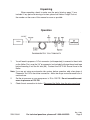
®
6 IN 1 AIR FRAMING NAILER
Model 91044
ASSEMBLY and OPERATING
INSTRUCTIONS
3491 Mission Oaks Blvd., Camarillo, CA 93011
Visit our Web site at http://www.harborfreight.com
TO PREVENT SERIOUS INJURY,
READ AND UNDERSTAND ALL WARNINGS
AND INSTRUCTIONS BEFORE USE.
Copyright© 2004 by Harbor Freight Tools®. All rights reserved. No portion of
this manual or any artwork contained herein may be reproduced in any shape
or form without the express written consent of Harbor Freight Tools.
For technical questions and replacement parts, please call 1-800-444-3353
Revised 07/04
Specifications
Air Inlet
Recommended Air Pressure
Maximum Air Pressure
Nail Type
1/4” NPT
70-125 PSI *
125 PSI
Approx. 10 Gauge (0.113 & 0.131” Dia.) Clipped or Full Head Nails
2-3/16” - 3-1/2” Length
Safety Feature
Full Sequential Actuation
Magazine Capacity
21° - 60 Qty., 28° and 34° - 100 Qty.
Air Consumption
8-12 CFM @ 90 PSI
Includes: 21° Full Head Nails - 50 Qty., 28° Clip Head Nails - 50 Qty.,
34° Clip Head Nails - 80 Qty., Goggles, Wrenches, and Case.
* The air pressure setting must not exceed job site regulations/restrictions. The air
pressure setting must not exceed 90 PSI when being used with work pieces that
have a thickness of less than 1-3/4”.
Save This Manual
You will need the manual for the safety warnings and precautions, assembly instructions,
operating and maintenance procedures, parts list and diagram. Keep your invoice with this
manual. Write the invoice number on the inside of the front cover. Keep the manual and
invoice in a safe and dry place for future reference.
Safety Warnings and Precautions
WARNING: When using tool, basic safety precautions should always be followed to reduce the risk of personal injury and damage to equipment.
Read all instructions before using this tool!
1.
Keep work area clean. Cluttered areas invite injuries.
2.
Observe work area conditions. Do not use machines or power tools in damp or wet
locations. Don’t expose to rain. Keep work area well lit. Do not use electrically powered
tools in the presence of flammable gases or liquids.
3.
Keep children away. Children must never be allowed in the work area. Do not let them
handle machines, tools, extension cords, or air hoses.
4.
Store idle equipment. When not in use, tools must be stored in a dry location to inhibit
rust. Always lock up tools and keep out of reach of children.
5.
Use the right tool for the job. Do not attempt to force a small tool or attachment to do
the work of a larger industrial tool. There are certain applications for which this tool was
designed. It will do the job better and more safely at the rate for which it was intended.
Do not modify this tool and do not use this tool for a purpose for which it was not intended.
6.
Dress properly. Do not wear loose clothing or jewelry as they can be caught in moving
parts. Protective, electrically nonconductive clothes and nonskid footwear are
recommended when working. Wear restrictive hair covering to contain long hair.
7.
Use eye and ear protection. Always wear ANSI approved impact safety goggles.
Wear a full face shield if you are producing metal filings or wood chips. Wear an
ANSI approved dust mask or respirator when working around metal, wood, and
chemical dusts and mists. Other people in the work area must also wear ANSI
approved impact safety goggles.
REV 06/05 REV 11/06
SKU 91044
For technical questions, please call 1-800-444-3353.
Page 2
8.
Do not overreach. Keep proper footing and balance at all times. Do not reach over or across
running machines or air hoses.
9.
Maintain tools with care. Keep tools clean for better and safer performance. Follow
instructions for lubricating and changing accessories. Inspect tool cords and air hoses
periodically and, if damaged, have them repaired by an authorized technician. The handle
must be kept clean, dry, and free from oil and grease at all times. Do not operate a tool if any
portion of the tool’s operating controls are inoperable, disconnected, altered or not working
properly.
10.
Disconnect air supply. Disconnect air hose when adding nails, during maintenance, and
when not in use.
11.
Remove adjusting keys and wrenches. Check that keys and adjusting wrenches are
removed from the tool or machine work surface before attaching to an air source.
12.
Avoid unintentional starting. Be sure the trigger is in the Off position when not in use and
before plugging in. Do not carry any tool with your finger on the trigger, whether it is attached
to an air source or not. Do not point the tool towards yourself or anyone whether it contains
fasteners or not.
13.
Stay alert. Watch what you are doing, use common sense. Do not operate any tool when you
are tired.
14.
Check for damaged parts. Before using any tool, any part that appears damaged should be
carefully checked to determine that it will operate properly and perform its intended function.
Check for alignment and binding of moving parts; any broken parts or mounting fixtures; and
any other condition that may affect proper operation. Any part that is damaged should be
properly repaired or replaced by a qualified technician. Do not use the tool if any the trigger
does not operate properly.
15.
Guard against electric shock. Prevent body contact with grounded surfaces such as pipes,
radiators, ranges, and refrigerator enclosures.
16.
Replacement parts and accessories. When servicing, use only identical replacement parts.
Use of any other parts will void the warranty. Only use accessories intended for use with this
tool.
17.
Do not operate tool if under the influence of alcohol or drugs. Read warning labels if
taking prescription medicine to determine if your judgement or reflexes are impaired while
taking drugs. If there is any doubt, do not operate the tool.
18.
Use proper size and type extension cord. If an extension cord is required, it must be of the
proper size and type to supply the correct current to the compressor without heating up.
Otherwise, the extension cord could melt and catch fire, or cause electrical damage to the
tool. Check your air compressor’s manual for the appropriate size cord.
19.
Maintenance. For your safety, maintenance should be performed regularly by a qualified
technician.
20.
Compressed air only. Never use combustible gas as a power source.
21.
SKU 91044
Do not load nails with the trigger or safety depressed. Unintentional firing may
occur. Do not load nails when the air hose is connected to the tool. Always assume
that the tool contains fasteners.
For technical questions, please call 1-800-444-3353.
Page 3
22. Fire fasteners into an appropriate work surface only. Do not attempt to fire
fasteners into surfaces too hard to penetrate. Do not drive fasteners on top of other
fasteners, or at too steep of an angle. Fasteners can ricochet causing personal injury.
23. Do not fire fasteners too close to the edge of a workpiece. They may split the
workpiece and fly free, causing personal injury.
24. Disconnect air supply before loading Nailer. Before reloading (or making any
adjustments) to the Nailer make sure that the compressed air is disconnected.
25.
Take caution as some woods contain preservatives such as copper chromium
arsenate (CCA) which can be toxic. When stapling or nailing these materials extra
care should be taken to avoid inhalation and minimize skin contact.
WARNING: Some dust created by power sanding, sawing, grinding, drilling, and other
construction activities, contain chemicals known [to the State of California] to
cause cancer, birth defects or other reproductive harm.
Some examples of these chemicals are:
• Lead from lead-based paints
• Crystalline silica from bricks and cement or other masonry products
• Arsenic and chromium from chemically treated lumber
(California Health & Safety Code § 25249.5, et seq. )
26.
Stay within air pressure capacity. Never operate the Nailer above 125 PSI.
27.
Hold tool away from head and body. During operation the Nailer may kick back causing
injury.
28.
Transport Nailer safely. Always disconnect air supply when moving the tool in the
workplace. Carry the tool by the handle and avoid contact with the trigger.
Note: Performance of the compressor (if powered by line voltage) may vary depending on
variations in local line voltage. Extension cord usage may also affect tool
performance.
Warning: The warnings, cautions, and instructions discussed in this instruction manual
cannot cover all possible conditions and situations that may occur. It must be understood by the operator that common sense and caution are factors which cannot be
built into this product, but must be supplied by the operator.
Rev 11/06
SKU 91044
For technical questions, please call 1-800-444-3353.
Page 4
Unpacking
When unpacking, check to make sure the parts listed on page 11 are
included. If any parts are missing or broken, please call Harbor Freight Tools at
the number on the cover of this manual as soon as possible.
Operation
1/4” NPT
Nailer
1.
You will need to prepare a 1/4” air connector (sold separately) to connect to the air inlet
on the Nailer. First, wrap the 1/4” air connector (not included) with pipe thread seal tape
before threading it into the Air Inlet (90). Connect the 3/8” ID Air Source Hose to the
Nailer.
Note: If you are not using an automatic oiler system, before operation, add a few drops of
Pneumatic Tool Oil to the airline connection. Add a few drops more after each hour of
continual use.
2.
Set the air pressure on your compressor to 70 to 125 PSI. Do not exceed the maximum air pressure of 125 PSI.
3.
Check the air connection for leaks. Disconnect the Nailer from the air source hose.
Rev 11/06
SKU 91044
For technical questions, please call 1-800-444-3353.
Page 5
Operation
Testing the Full Sequential Safety Trip Mechanism
Warning: Even though the nailer should be empty during this procedure,
ALWAYS point the nailer at a piece of scrap wood when testing.
1.
Make sure the tool is disconnected from the power supply.
2.
Completely empty the Magazine (76) of nails.
3.
The Nailer should not fire if the Safety (41) is not depressed against the workpiece.
4.
Make sure the Trigger (47) and Safety (41) move freely, without sticking.
5.
Connect the air supply to the tool at the Air Inlet (90). Set the regulator at the recommended 70 to 125 PSI.
6.
Test the tool by depressing the Safety (41) against the workpiece without pulling the
Trigger (47). The Tool must not cycle (fire). If it cycles (fires), stop immediately and
have it repaired by a qualified service technician.
7.
Hold the tool away or off of the workpiece. The Safety (41) of the tool should return to
its original position. Squeeze the Trigger (47). The tool should not cycle (fire). If the
tool fires, stop immediately and have it repaired by a qualified service technician.
8.
Depress the Safety (41) against the workpiece and squeeze the Trigger (47). The tool
must cycle (fire) only once. Release the Trigger and squeeze it again. The tool
must not cycle (fire). With the Trigger held, carefully lift the nailer and press it against
the workpiece again. The tool must not cycle (fire). If it fails to perform in the manner
explained in bold, have it repaired by a qualified service technician.
Warning! Disconnect the Nailer from the air compressor whenever loading or servicing.
ALWAYS WEAR ANSI APPROVED IMPACT SAFETY GOGGLES WHEN RELOADING OR DOING ANY OTHER MAINTENANCE ON THIS TOOL.
Other people in the work area must also wear ANSI approved impact
safety goggles.
Loading Nails - See FIGURE 2 on page 7.
1.
Slide the Tab (70) back and the Latch (83) will hold it in place.
2.
Load a stick of nails into the top slot, making sure the nail heads are facing up.
3.
Be Careful. When you pull back on the Latch (83) to release the Tab (70), it will spring
forward with force. Keep your fingers clear when you release the Latch (83) and slide
the Tab (70) forward.
Note: The Nailer may not work if there are only two or three nails left in the tool. If there are
only a few nails remaining, simply load another strip of nails into the Magazine behind
the few remaining nails and the Nailer will be ready for further use.
Rev 11/06
SKU 91044
For technical questions, please call 1-800-444-3353.
REV 06/05
Page 6
Operation (continued)
Warning! Disconnect the Nailer from the air compressor
whenever loading or servicing.
FIGURE 2
FIGURE 1
Exhaust Cover (4)
Tab (70)
Trigger (47)
Air Inlet (90)
Latch (83)
Safety (41)
Magazine (76)
FIGURE 4
FIGURE 3
Adjustment Knob (81)
Angle Adjustment Holes
Tab (70)
Hex Bolt
21o 28o 34o
FIGURE 6
FIGURE 5
28o/34o
34o
28o
Pin in
B
28o /34o
Position
21o
Plate (80) Pin in
A
21o
Position
21o
REV 04/06
SKU 91044
For technical questions, please call 1-800-444-3353.
Page 7
Operation (continued)
Operating the Nailer
Note: The Nailer may not work if there are only 2 or 3 nails left-see Note on page 6, bottom.
1.
Set the proper angle of the Nailer for your application (a three step process):
a. Pull back and engage the Tab (70), exposing three adjustment holes. Loosen
the hex bolt and slide it into the appropriate hole (21°, 28°, 34°). Retighten the
hex bolt securely, making sure it fits into the appropriate hole properly. See
FIGURE 3. Gently release the Tab (70).
b. Remove the Adjustment Knob (81). See FIGURE 4. Move the Magazine (76)
so that the desired hole on the Plate (80) lines up with the nut on the Magazine
(76). See FIGURE 5. Replace and tighten the Adjustment Knob (81).
c. Inspect the Pin’s (34) location and compare it to FIGURE 6. If you are driving
21° angle nails the Pin should be in the lower hole (position A). If you are
driving 28° or 34° angle nails the Pin should be in the upper hole (position B).
If the Pin is in the wrong position, pull the Pin (34) out (it is held in place with a
rubber washer), reposition the Guide Plate (35), and reinsert and secure the
Pin (34). Before using the nailer, be sure that the Pin is properly secured.
2.
The driving depth of a nail can be adjusted in two ways. First, by increasing or decreasing air pressure (never to exceed the maximum of 125 PSI). Secondly, by loosening the Screw (37) and adjusting the Bracket A (38). We recommend you experiment in a scrap piece of material to determine how far to adjust the unit.
3.
Attach the Nailer to the air supply at the Air Inlet (90). See FIGURE 1. Start your air
compressor and make sure it is set to between the recommended 70-125 PSI and not
over the maximum 125 PSI.
4.
To fire, place the Safety (41) of the Nailer on the workpiece. The Nailer should not fire
if the Safety (41) is not depressed. Once depressed, quickly squeeze the Trigger (47)
once. Do not fire repeatedly; nails could bounce off of one another causing injury. We recommend you practice with a piece of scrap material.
5.
The Exhaust Cover (4) may be turned to suit your preference. See FIGURE 1 on page
7.
6.
The Rubber Cover (42) provides a non-marring surface. If desired, the Rubber Cover
may be removed to expose the teeth on Safety (41). Doing so provides a nonslip
surface and can improve accuracy.
7.
When finished, disconnect the Nailer from the air source.
Rev 11/06
SKU 91044
For technical questions, please call 1-800-444-3353.
Page 8
Anytime any maintenance or repairs are done (including clearing jams), FIRST:
1.
2.
3.
4.
Disconnect the Nailer from the air hose.
Empty the Magazine (76) completely.
Attempt to fire the Nailer into a piece of scrap wood to ensure that it is disconnected and
is incapable of firing any nails.
Always leave the Magazine (76) open during maintenance. The Magazine is springloaded and may cause parts or a nail to fly out of the Nailer.
Clearing Jams
1.
Disconnect tool from air hose. Always fire the trigger repeatedly to make sure all of the
air is expended from the Nailer.
2.
If a nail is jammed in the discharge area, simply remove it with pliers.
3.
If a nail is jammed in the magazine, pull the Tab (70)
all the way back to the engaged position. Using a
screwdriver, attempt to release the jammed nail by
probing either or both of the two openings in the
magazine (see photo at right) to release the nail.
Pull out the jammed nail and the remainder of the
nail strip that is still in the magazine.
4.
Dispose of the remaining nail strip; it may be bent
or damaged in some other way. Reload the magazine with a new nail strip.
Figure 7
Probe in these areas with a
screwdriver to release jammed nails.
Be careful. When you pull back on the Latch (83) to
release the Tab (70), it will spring forward with
force. Keep your fingers clear when you release the Latch (83) and slide the Tab (70)
forward.
If you are unable to clear the nail jam using the method prescribed above, the tool
should be taken to a qualified service technician for proper servicing.
SKU 91044
For technical questions, please call 1-800-444-3353.
Page 9
Troubleshooting
Any internal repair should be performed by an authorized service technician.
Symptom
Cause
Solution
Top of tool or Trigger
(47) leaks air
Loose Screws,
Worn or damaged O-rings or seals
Verify screws are tight,
Check/replace O-rings or seals
Sluggish operation, or
will not operate
Inadequate air supply,
Inadequate lubrication,
Worn/damaged O-rings or seals
Use a compressor that delivers
the proper CFM,
Add air tool oil (not incl.),
Check/replace O-rings or seals
Bottom of tool leaks air
Loose Screws,
Worn/damaged O-rings, seals.
Verify screws are tight,
Check/replace O-rings, seals.
Frequent Jamming
Incorrect fasteners,
Damaged fasteners,
Magazine (76) or Nose screw loose,
Dirt inside Magazine,
Worn or damaged Driver Unit
Verify fastener size,
Replace fasteners,
Tighten screws,
Clean Magazine,
Inspect Driver Unit
Note: Contact Harbor Freight Tools for repair/replacement parts.
Maintenance
Disconnect the Nailer from the air source hose before attempting any maintenance.
1.
Wipe tool clean with a lint free cloth and inspect it for damage. Do not use the tool if
you find damage. Have it repaired by an authorized service technician.
2.
Always test the Full Sequential Safety mechanism before each use (see page 6).
3.
Keep all screws tight. Loose screws may damage the tool and cause personal injury.
4.
Make sure that Base (29) is clear of all dirt or debris.
SKU 91044
For technical questions, please call 1-800-444-3353.
Page 10
Parts List
Part
Description
Part
Description
Part
Description
1
Screw
31
Screw
61
Bushing
2
Spring Washer
32
Washer
62
Screw
3
Bushing
33
Pin
63
Washer
4
Exhaust Cover
34
Pin
64
Turn Plate B
5
Seal
35
Guide Plate
65
Bushing
6
Screw
36
Spring
66
Coil Spring
7
Spring Washer
37
Screw
67
Coil Spring Base
8
Cylinder Cap
38
Bracket A
68
Pin
9
Gasket
39
Washer
69
Screw
10
O-ring
40
Screw
70
Tab
11
O-ring
41
Safety (Bracket B)
71
Feeder Shoe
12
Spring
42
Rubber Cover
72
Hex Bolt
13
Valve
43
Washer
73
Washer
14
Valve Seal
44
Pin
75
Screw
15
O-ring
45
Safe Guide
76
Magazine
16
Valve Seat
46
Trigger Spring
77
Screw
17
Screw
47
Trigger
78
Rail
18
Bushing
48
Seal
79
Nut
19
Washer
49
Trigger Valve Head
80
Plate
20
O-ring
50
Spring
81
Adjustment Knob
21
Piston Assembly
51
O-ring
82
Suppor t
22
O-ring
52
Trigger Valve Stem
83
Latch
23
Cylinder
53
O-ring
84
Torsion Spring
24
O-ring
54
Trigger Valve Guide
85
Bushing
25
Bumper A
55
Spring Pin
86
Nut
26
Bumper B
56
Screw
87
Grip Sleeve
27
Body
57
Spring Washer
88
O-ring
28
O-ring
58
Nut
89
End Cap
29
Base
59
Washer
90
Air Inlet
30
Spring Washer
60
Turn Plate A
91
)Washer
PLEASE READ THE FOLLOWING CAREFULLY
THE MANUFACTURER AND/OR DISTRIBUTOR HAS PROVIDED THE PARTS DIAGRAM IN THIS
MANUAL AS A REFERENCE TOOL ONLY. NEITHER THE MANUFACTURER NOR DISTRIBUTOR MAKES
ANY REPRESENTATION OR WARRANTY OF ANY KIND TO THE BUYER THAT HE OR SHE IS QUALIFIED
TO MAKE ANY REPAIRS TO THE PRODUCT OR THAT HE OR SHE IS QUALIFIED TO REPLACE ANY
PARTS OF THE PRODUCT. IN FACT, THE MANUFACTURER AND/OR DISTRIBUTOR EXPRESSLY STATES
THAT ALL REPAIRS AND PARTS REPLACEMENTS SHOULD BE UNDERTAKEN BY CERTIFIED AND LICENSED TECHNICIANS AND NOT BY THE BUYER. THE BUYER ASSUMES ALL RISK AND LIABILITY
ARISING OUT OF HIS OR HER REPAIRS TO THE ORIGINAL PRODUCT OR REPLACEMENT PARTS
THERETO, OR ARISING OUT OF HIS OR HER INSTALLATION OF REPLACEMENT PARTS THERETO.
NOTE: Some parts are listed and shown for illustration purposes only and are not available
individually as replacement parts.
REV 06/05
SKU 91044
For technical questions, please call 1-800-444-3353.
Page 11
Assembly Drawing
REV 06/05
SKU 91044
For technical questions, please call 1-800-444-3353.
Page 12