1
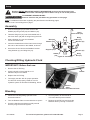
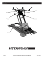
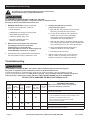
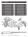
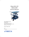
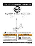
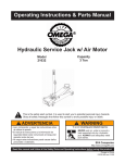
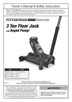
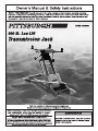
Specifications
Weight Capacity
800 lb.
Maximum Height
22-1/2"
Tilt
55º forward, 8º back, 30º side
Minimum Height
8-1/2"
WARNING SYMBOLS AND DEFINITIONS
This is the safety alert symbol. It is used to alert you to potential personal injury hazards.
Obey all safety messages that follow this symbol to avoid possible injury or death.
Indicates a hazardous situation which, if not avoided,
will result in death or serious injury.
Indicates a hazardous situation which, if not avoided,
could result in death or serious injury.
Indicates a hazardous situation which, if not avoided,
could result in minor or moderate injury.
Addresses practices not related to personal injury.
IMPORTANT SAFETY INFORMATION
Read all safety warnings and instructions.
Save all warnings and instructions for future reference.
Failure to heed these markings may result in personal injury and/or property damage:
1. Study, understand, and follow all instructions
before operating this device.
2. Do not exceed 800 lb. rated capacity.
9. Lower load slowly.
10. Do not use for aircraft purposes.
3. Use only on hard, level surfaces.
11. Inspect before every use;
do not use if parts loose or damaged.
4. Adequately support the vehicle
before starting repairs.
12. Do not alter the jack or use attachments and/or
adapters that are not supplied by the manufacturer.
5. Use of this product is limited to the removal,
installation, and transportation in the lowered position,
of transmissions, transfer cases, and transaxles.
13. The warnings, precautions, and instructions
discussed in this manual cannot cover all
possible conditions and situations that may occur.
The operator must understand that common sense
and caution are factors, which cannot be built into
this product, but must be supplied by the operator.
6. Do not adjust safety valve.
7. Wear ANSI-approved safety goggles and
heavy-duty work gloves during use.
8. Keep clear of load while lifting and lowering.
14. The brass components of this product contain lead,
a chemical known to the State of California to cause
cancer, birth defects (or other reproductive harm).
(California Health & Safety Code § 25249.5, et seq.)
SAVE THESE INSTRUCTIONS.
Page 2
For technical questions, please call 1-800-444-3353.
Item 69685
Setup
Read the ENTIRE IMPORTANT SAFETY INFORMATION section at the beginning of this
manual including all text under subheadings therein before set up or use of this product.
TO PREVENT SERIOUS INJURY:
Remove load from the jack before any procedure on this page.
Note: For additional information regarding the parts listed in the following pages,
refer to Parts List and Diagram on page 7.
Assembly
1. Connect a Support (41) to each corner of the
Saddle (32) using a Bolt (39) and Washer (40).
Chain
Hook (38)
2. Thread a Wing Nut (37) onto the threaded end of
the Chain Hook (38) with its wings facing the hook.
3. Slide a Washer (31) onto the threaded
end of the Chain Hook.
Bolt (39)
Washer (40)
Wing
Nut (37)
Washer (31)
4. Insert the threaded end of the Chain Hook through
the hole on the bracket on the Saddle, as shown.
5. Secure the Chain Hook to the Saddle’s bracket
using Washer (31) and Wing Nut (37).
Support (41)
Saddle
(32)
Figure A: Assembly
Washer (31)
Wing
Nut (37)
Checking/Filling Hydraulic Fluid
IMPORTANT! Before first use:
1. Remove the Oil Fill Plug.
2. Check hydraulic oil level and fill to 1/4"
below the fill port as needed.
Oil Fill
Plug
Handle
3. Replace the Oil Fill Plug.
4. Thoroughly test the Jack for proper operation.
If it does not work properly, bleed air from its
hydraulic system as described in Bleeding, below.
Release
Valve
Figure B: Hydraulic Fluid Service Parts
Bleeding
1. Follow the Checking/Filling Hydraulic Fluid
instructions above.
4. Check hydraulic oil level and fill to
1/4" below the fill port as needed.
2. Turn the Release Valve counterclockwise to open it.
5. Replace the Oil Fill Plug and close the
Release Valve by turning it clockwise.
3. Pump the Handle up and down quickly several
times to purge air from the system.
Item 69685
For technical questions, please call 1-800-444-3353.
Page 3
Functions
Support
Saddle
Chain
tab
Side Tilt
Knob
Forward
Tilt Knob
Handle
Release
Valve
Page 4
For technical questions, please call 1-800-444-3353.
Item 69685
Operation
Read ENTIRE IMPORTANT SAFETY INFORMATION section at beginning of this manual
including all text under subheadings therein before set up or use of this product.
Removing a Transmission
1. Before every use, check and/or fill Hydraulic Fluid.
2. Once the vehicle is raised and secured on a lift, clear
the area underneath the vehicle of people and tools.
3. Remove the Chain and set aside.
4. Move the Transmission Jack
underneath the transmission.
5. Close the Release Valve.
6. Pump the Handle to raise the Transmission Jack.
7. Stop just below the transmission and align the
Saddle to the Transmission with the Tilt Knobs.
8. Continue raising the Saddle up to the transmission
to determine where you will need to adjust
the Supports. All four Supports need to grip
and make contact with the transmission.
9. After determining where they need to be set,
loosen the threaded bolts on each Support,
and adjust it to the proper setting
for the transmission. Tighten the bolts.
10. Raise the unit again to make contact
with the transmission, making sure all of
the Supports are in firm contact.
11. Hook the chain on the open bracket,
wrap the Chain securely around the transmission,
and hook the chain hook through the other end.
Tighten the Chain Hook securely to tighten the chain.
12. Once it is securely fastened, release the
bolts holding the transmission in place.
13. Make sure the area is clear of people and tools, and
verify that the transmission is securely held in place.
Then, slowly open the Release Valve
to lower the Transmission Jack.
14. Move the Transmission Jack from under the
vehicle and perform your desired maintenance.
Replacing a Transmission
1. Move the Transmission Jack so that the transmission
is lined up properly with its connection points.
5. Double-check to make sure the
transmission is securely installed.
2. Close the Release Valve.
6. Disconnect the Chain and remove it.
3. Pump the Handle to gradually raise the
Transmission Jack, while guiding it into place.
7. Clear the area near the Transmission Jack, and
slowly open the Release Valve to lower the Jack.
4. Secure the transmission into
place using its hardware.
8. Move the Transmission Jack clear of the vehicle.
Item 69685
For technical questions, please call 1-800-444-3353.
Page 5
Maintenance and Servicing
Procedures not specifically explained in this manual must
be performed only by a qualified technician.
TO PREVENT SERIOUS INJURY FROM TOOL FAILURE:
Do not use damaged equipment. If abnormal noise or vibration occurs,
have the problem corrected before further use.
1. BEFORE EACH USE, inspect the general
condition of the equipment. Check for:
4. Change the hydraulic oil at least
once every three years:
• loose hardware,
a. With the Jack fully lowered, remove the Oil
Filler Plug on the side of the Housing.
• misalignment or binding of moving parts,
b. Tip the Jack to allow the old hydraulic oil
to drain out of the Housing completely,
and dispose of the old hydraulic oil in
accordance with local regulations.
• visibly leaking hydraulic fluid,
• cracked or broken parts, and
• any other condition that may
affect its safe operation.
c. With the Jack upright, completely fill the Housing
with a high quality hydraulic oil (not included) until
the oil just begins to run out of the Oil Fill Hole.
2. Before each use and after the inspection,
thoroughly test the Jack for proper
operation prior to its actual use.
If the Jack appears not to be working properly,
follow Bleeding instructions on page 3.
d. Open the Release Valve and pump the
Handle to bleed air from the system.
e. Reinstall the Oil Filler Plug.
3. Periodically, inject grease into the Zerk fitting on
the main platform of the Transmission Jack.
5. Wipe dry with a clean cloth. Then, store the
Jack in a safe, dry location out of reach of
children and other non-authorized people.
Troubleshooting
TO PREVENT SERIOUS INJURY: Use caution when troubleshooting malfunctioning jack.
Stay clear of supported load. Completely resolve all problems before use.
If solutions presented in Troubleshooting guide do not solve the problem, have a qualified technician
inspect and repair jack before use. After jack is repaired: Test it carefully without a load by raising and
lowering it fully, checking for proper operation, BEFORE RETURNING JACK TO OPERATION.
DO NOT USE A DAMAGED OR MALFUNCTIONING JACK!
POSSIBLE SYMPTOMS
Jack will
not lift at
its weight
capacity
Saddle
lowers
under load
X
X
Pump
stroke
feels
spongy
Saddle will
not lift all
the way
PROBABLE SOLUTION
Handle
Oil leaking (Make certain that the Jack is not supporting
moves up
from Filler a load while attempting a solution.)
when Jack is
Plug
under load
Check that Release Valve is closed fully.
Bleed air from the system.
Valves may be blocked and may not close fully. To flush the valves:
X
X
X
1. Lower the Saddle and securely close the Release Valve.
X
X
2. Manually lift the Saddle several inches.
3. Open the release valve and force the Saddle
down as quickly as possible.
Jack may be low on oil. Check the oil level and refill if needed.
X
Jack may require bleeding - see instructions on page 3.
X
Page 6
Unit may have too much hydraulic oil inside,
check fluid level and adjust if needed.
For technical questions, please call 1-800-444-3353.
Item 69685
Parts List and Diagram
Part
1
2
3
4
5
6
7
8
9
10
11
12
13
14
15
16
17
18
19
20
21
Description
Bolt M6x14
Caster
Snap Ring Ø22
Flat Washer Ø6
Lock Washer Ø6
Nut M6
Inner Hex Bolt M8x16
Lock Washer Ø8
Big Flat Washer Ø8
Base Assembly
Hydraulic Assembly
Long Shaft
Cotter Pin M6x45
Lifting Arm Assembly
Long Connecting Rod
Snap Ring Ø16
Connecting Shaft
Shaft Sleeve
Short Connecting Rod
Forward Tilt Knob
Bracket
Qty
16
4
2
16
16
16
2
2
2
1
1
1
1
1
2
4
1
2
2
1
1
Part
22
23
24
25
26
27
28
29
30
31
32
33
34
35
36
37
38
39
40
41
42
Description
Spring Round Pin Ø4.5x25
Shaft
Bearing
Square Shaft
Nut M16
Snap Ring Ø18
Axle
Side Tilt Knob
Nut M12
Big Flat Washer Ø6
Saddle
Stepped Shaft
Lock Nut M10
Connect Shaft
Chain
Wing Nut M6
Chain Hook
Bolt M10x16
Flat Washer Ø10
Support
Handle Assembly
Qty
2
1
4
1
1
4
1
1
1
2
1
1
1
1
1
2
1
8
14
4
1
Record Product’s Serial Number Here:
Note: If product has no serial number, record month and year of purchase instead.
Note: Some parts are listed and shown for illustration purposes only,
and are not available individually as replacement parts.
Item 69685
For technical questions, please call 1-800-444-3353.
Page 7
PLEASE READ THE FOLLOWING CAREFULLY
THE MANUFACTURER AND/OR DISTRIBUTOR HAS PROVIDED THE PARTS LIST AND ASSEMBLY DIAGRAM
IN THIS MANUAL AS A REFERENCE TOOL ONLY. NEITHER THE MANUFACTURER OR DISTRIBUTOR
MAKES ANY REPRESENTATION OR WARRANTY OF ANY KIND TO THE BUYER THAT HE OR SHE IS
QUALIFIED TO MAKE ANY REPAIRS TO THE PRODUCT, OR THAT HE OR SHE IS QUALIFIED TO REPLACE
ANY PARTS OF THE PRODUCT. IN FACT, THE MANUFACTURER AND/OR DISTRIBUTOR EXPRESSLY
STATES THAT ALL REPAIRS AND PARTS REPLACEMENTS SHOULD BE UNDERTAKEN BY CERTIFIED AND
LICENSED TECHNICIANS, AND NOT BY THE BUYER. THE BUYER ASSUMES ALL RISK AND LIABILITY
ARISING OUT OF HIS OR HER REPAIRS TO THE ORIGINAL PRODUCT OR REPLACEMENT PARTS
THERETO, OR ARISING OUT OF HIS OR HER INSTALLATION OF REPLACEMENT PARTS THERETO.
Limited 90 Day Warranty
Harbor Freight Tools Co. makes every effort to assure that its products meet high quality and durability standards,
and warrants to the original purchaser that this product is free from defects in materials and workmanship for the
period of 90 days from the date of purchase. This warranty does not apply to damage due directly or indirectly,
to misuse, abuse, negligence or accidents, repairs or alterations outside our facilities, criminal activity, improper
installation, normal wear and tear, or to lack of maintenance. We shall in no event be liable for death, injuries
to persons or property, or for incidental, contingent, special or consequential damages arising from the use of
our product. Some states do not allow the exclusion or limitation of incidental or consequential damages, so the
above limitation of exclusion may not apply to you. THIS WARRANTY IS EXPRESSLY IN LIEU OF ALL OTHER
WARRANTIES, EXPRESS OR IMPLIED, INCLUDING THE WARRANTIES OF MERCHANTABILITY AND FITNESS.
To take advantage of this warranty, the product or part must be returned to us with transportation charges
prepaid. Proof of purchase date and an explanation of the complaint must accompany the merchandise.
If our inspection verifies the defect, we will either repair or replace the product at our election or we may
elect to refund the purchase price if we cannot readily and quickly provide you with a replacement. We will
return repaired products at our expense, but if we determine there is no defect, or that the defect resulted
from causes not within the scope of our warranty, then you must bear the cost of returning the product.
This warranty gives you specific legal rights and you may also have other rights which vary from state to state.
3491 Mission Oaks Blvd. • PO Box 6009 • Camarillo, CA 93011 • (800) 444-3353