1
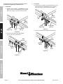
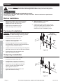
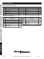
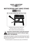
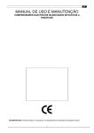
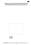
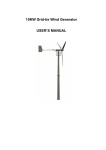
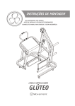
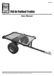
Owner’s Manual & Safety Instructions
Save This Manual Keep this manual for the safety warnings and precautions, installation, operating,
inspection, maintenance and cleaning procedures. Write the product’s serial number in the back of the manual
near the assembly diagram (or month and year of purchase if product has no number). Keep this manual and
the receipt in a safe and dry place for future reference.
ITEM 61407
800 lb capacity
full size
truck Rack
Visit our website at: http://www.harborfreight.com
Email our technical support at: [email protected]
When unpacking, make sure that the product is intact
and undamaged. If any parts are missing or broken,
please call 1-800-444-3353 as soon as possible.
Copyright© 2013 by Harbor Freight Tools®. All rights reserved.
No portion of this manual or any artwork contained herein may be reproduced in
any shape or form without the express written consent of Harbor Freight Tools.
Diagrams within this manual may not be drawn proportionally. Due to continuing
improvements, actual product may differ slightly from the product described herein.
Tools required for installation and service may not be included.
Read this material before using this product.
Failure to do so can result in serious injury.
Save this manual.
Important Safety Information
Safety
Read all safety warnings and instructions.
Failure to follow the warnings and instructions may result in serious injury.
Save all warnings and instructions for future reference.
Installation Precautions
1. Follow DOT regulations regarding
installation and use.
2. Park truck on a flat, level, hard surface well away
from traffic. Place transmission in park/neutral
and set parking brake.
3. Verify that installation surface has no hidden
wires before drilling or driving screws.
Setup
4. Install only according to these instructions.
Improper installation can create hazards.
5. Wear ANSI-approved safety goggles and
heavy-duty work gloves during
assembly and installation.
6. Mount Truck Rack securely to vehicle.
7. Keep installation area clean and well lit.
8. Keep bystanders out of the area during installation.
9. Do not install when tired or when under
the influence of drugs or medication.
10. Weight capacity and other product capabilities apply
to properly and completely installed product only.
Use Precautions
1. Do not exceed rated weight capacity of
Truck Rack, distributed evenly.
Be aware of dynamic loading! Sudden
load movement may briefly create excess
load causing product failure.
Operation
2. Do not exceed rated weight capacity of truck.
Refer to truck’s Gross Vehicle Weight Rating.
3. Strap load securely to Truck Rack.
4. Use as intended only.
5. Inspect before every use; do not use
if parts loose or damaged.
6. This product is not a toy. Do not allow
children to play with or near this item.
7. Maintain product labels and nameplates.
These carry important safety information.
If unreadable or missing, contact
Harbor Freight Tools for a replacement.
8. The warnings, precautions, and instructions
discussed in this instruction manual cannot cover all
possible conditions and situations that may occur.
It must be understood by the operator that
common sense and caution are factors
which cannot be built into this product, but
must be supplied by the operator.
Save these instructions.
Specifications
Maintenance
Load Capacity
Weight
Dimensions
Mounting Hardware
(for permanent
installation)
Page 2
800 lb
160 lb
138″ L x 60″ W x 34" H
(height of Legs with Risers)
12x M12x70 Bolts
24x Ø12 Washers
12x Ø12 Spring Washers
12x Ø12 Nuts
(sold separately)
For technical questions, please call 1-800-444-3353.
Item 61407
Assembly
General Assembly
Note: Finger tighten all connections until
assembly is done.
All connections are made to both left and right sides.
Assemble on a flat, level, hard surface.
A
B
C
D
E
F1
F2
G
H
I
J
Description
Bolt (M16x30), Washer x2, Nut
Bolt (M12x50), Washer, Nut
Bolt (M10x35), Washer
Bolt (M10x35), Washer, Nut
Bolt (M12x75), Washer, Nut
Bolt (M18x85), Spring Washer,
Washer x2, Nut
Bolt (M18x85), Spring Washer,
Washer x2, Nut
Bolt (M12x70), Spring Washer,
Washer (Ø12), Washer (Ø16), Nut
Bolt (M10x70), Spring Washer,
Washer, Nut
J-Hook, Spring Washer, Washer, Nut
Bolt (M18x70), Washer x2, Nut
2. Attach curved ends of Rear Side Bars
to Rear Legs using Bolt Set D.
Qty.
Bolt Set B
4
8
2
2
2
4
4
Rear Side
Bar (3)
Setup
Bolt
Set
1. Position Rear Legs (6, 7) on Rear Side Bars (3).
Attach using Bolt Set B.
Safety
Read the entire Important Safety Information section at the beginning of this manual
including all text under subheadings therein before set up or use of this product.
Bolt
Set D
8
2
Rear
Left Leg
8
4
Figure A: Bolt Set Contents
Figure B
Operation
3. Attach Rear Bar (12) to Rear Side
Bars using Bolt Set G.
4. Attach end caps with Bolt Set C.
Bolt Set C
Washer
(Ø12)
Washer
(Ø16)
Bolt
Set G
Figure C
Item 61407
For technical questions, please call 1-800-444-3353.
Page 3
Maintenance
Rear
Bar (12)
If the truck has a short bed, go to instruction 5.
If it has a long bed, go to instruction 6.
5. Short Bed:
Safety
a. Position the Front Bar (10) behind the Cross
Bars on the Front Side Bars (2), then position
the Front Legs (4, 5) next to the Front Bar.
Fr
on
t
6. Long Bed:
a. Position the Front Bar (10) in front of the Cross
Bars on the Front Side Bars (2), then position
the Front Legs (4, 5) next to the Front Bar.
Fr
on
t
Front
Bar (10)
Cross
Bar
Front
Bar (10)
Front
Right Leg
Setup
Front
Right Leg
Cross
Bar
Front Side
Bar (2)
Figure D
Front Side
Bar (2)
Figure F
b. Secure connections with Bolt Sets B and G.
b. Secure connections with Bolt Sets B
and G, then go to instruction 7.
Bolt
Set B
Bolt
Set B
Washer
(Ø12)
Operation
Bolt
Set G
Washer
(Ø16)
Washer
(Ø16)
Washer
(Ø12)
Bolt
Set G
Figure G
Figure E
Maintenance
Page 4
For technical questions, please call 1-800-444-3353.
Item 61407
Rear Side
Bar (3)
9. Position the Center Bar (11), where desired, on
the Rear Side Bars, to the rear of the middle
connections. Attach with Bolt Set E.
Clamp
(13)
Bolt
Set E
Re
ar
Middle
Connection
Clamp
(13)
Front Side
Bar (2)
Bolt Set A
Center
Bar (11)
Safety
7. Slide Rear Side Bars (3) into Front Side Bars (2).
Secure connections with Clamps (13) and Bolt Set A.
Rear
Side Bar
Figure H
Figure J
Setup
8. Slide ends of Cab Bar (1) over Front Side Bars.
Attach with Bolt Set H.
Front
Side Bar
Bolt
Set H
Figure I
Attaching the Feet
1. Measure the height of the Truck Rack and determine
if additional height is needed to clear the truck’s cab.
3. Attach Feet (8L, 8R, 9L, 9R) to corresponding Legs
so that the lips will face inside the truck bed.
2. If additional height is needed, attach
Risers (14) to bottoms of Legs with Bolt Set J.
4. Attach with Bolt Sets F1 and F2.
Operation
Cab Bar
(1)
Rear Left
Leg
Leg
Bolt Set J
Riser
(14)
Figure K
Rear Left
Foot
Bolt Set F2
Lip
(Facing inside
the truck bed)
Figure L
Item 61407
For technical questions, please call 1-800-444-3353.
Page 5
Maintenance
Bolt Set F1
Installation
Read the entire Important Safety Information section at the beginning of this
manual including all text under subheadings therein before set up or use of this product.
Safety
TO PREVENT SERIOUS INJURY During installation:
Park truck on a flat, level, hard surface well away from traffic. Place transmission in park/neutral
and set parking brake.
Before Installation
1. Measure the length of the truck bed with the
tailgate closed, then measure the distance
between the Front and Rear Legs.
2. Adjust the Front and Rear Legs to
match the length of the truck bed.
3. With assistance, lift the Truck
Rack onto the truck bed.
Setup
4. Position the Legs as close to the corners
of the truck bed’s rails as possible. Adjust
the legs to avoid obstructions on the
underside of rails at installation points.
Permanent Installation
Hardware
(sold separately)
WARNING! Verify that installation surface has no
hidden wires or before drilling or driving screws.
1. Position the Feet so that the lips are
flush with the insides of the rails.
Bed
Rail
2. Using the Feet as templates, mark
locations of mounting holes.
Operation
3. Drill holes appropriate for the proper hardware
(sold separately), described under Specifications
on page 2, at the marked locations.
Foot
4. Position the Feet so that mounting holes align with
pilot holes, then secure the Feet with the hardware.
Figure M
5. Square and level all components, then
tighten all hardware securely.
Temporary Installation
1. Position the Feet so that the lips are
flush with the insides of the rails.
2. Using Bolt Set I, insert the J-Hooks up
through the mounting tubes on each Foot.
Maintenance
3. Secure from the top, tightening hardware
until the J-Hooks are holding the Feet
tightly against the bed rail.
Bed
Rail
Foot
4. Square and level all components, then
tighten all hardware securely.
Bolt
Set I
Figure N
Page 6
For technical questions, please call 1-800-444-3353.
Item 61407
Maintenance and Servicing
Safety
Procedures not specifically explained in this manual must
be performed only by a qualified technician.
To prevent serious injury from Truck Rack failure:
Do not use damaged equipment. If Truck Rack is damaged or if abnormal noise
or vibration occurs, have the problem corrected before further use.
1. BEFORE EACH USE, inspect the general
condition of the Truck Rack. Check for:
2. After Use, wipe external surfaces of
the Truck Rack with clean cloth.
• loose hardware,
• misalignment or binding of moving parts,
• cracked or broken parts, and
Maintenance
Operation
Setup
• any other condition that may
affect its safe operation.
Item 61407
For technical questions, please call 1-800-444-3353.
Page 7
PLEASE READ THE FOLLOWING CAREFULLY
Safety
The manufacturer and/or distributor has provided the parts list and assembly diagram
in this document as a reference tool only. Neither the manufacturer or distributor
makes any representation or warranty of any kind to the buyer that he or she is
qualified to make any repairs to the product, or that he or she is qualified to replace
any parts of the product. In fact, the manufacturer and/or distributor expressly
states that all repairs and parts replacements should be undertaken by certified and
licensed technicians, and not by the buyer. The buyer assumes all risk and liability
arising out of his or her repairs to the original product or replacement parts
thereto, or arising out of his or her installation of replacement parts thereto.
Setup
Operation
Maintenance
Page 8
For technical questions, please call 1-800-444-3353.
Item 61407
Record Serial Number Here:
Note: If product has no serial number, record month and year of purchase instead.
Maintenance
Operation
Setup
Safety
Note: Some parts are listed and shown for illustration purposes only, and
are not available individually as replacement parts.
Item 61407
For technical questions, please call 1-800-444-3353.
Page 9
Parts List and Diagram
Components Parts List
Safety
Part
1
2
3
4
5
6
7
8L
Description
Cab Bar
Front Side Bar
Rear Side Bar
Front Right Leg
Front Left Leg
Rear Right Leg
Rear Left Leg
Front Left Foot
Qty.
Part
Qty.
Bolt
Set
1
2
2
1
1
1
1
1
8R
9L
9R
10
11
12
13
14
Description
Qty.
Description
Qty.
Front Right Foot
Rear Left Foot
Rear Right Foot
Front Bar
Center Bar
Rear Bar
Clamp
Riser
1
1
1
1
1
1
4
4
Hardware Parts List
Bolt
Set
Setup
A
B
C
D
E
F1
F2
Description
Bolt (M16x30), Washer x2, Nut
Bolt (M12x50), Washer, Nut
Bolt (M10x35), Washer
Bolt (M10x35), Washer, Nut
Bolt (M12x75), Washer, Nut
Bolt (M18x85), Spring Washer,
Washer x2, Nut
Bolt (M18x85), Spring Washer,
Washer x2, Nut
4
8
2
2
2
4
G
H
I
J
Bolt (M12x70), Spring Washer,
Washer (Ø12), Washer (Ø16), Nut
Bolt (M10x70), Spring Washer,
Washer, Nut
J-Hook (M12x70), Spring Washer
Washer, Nut
Bolt (M18x70), Washer x2, Nut
8
2
8
4
4
Operation
Maintenance
Page 10
For technical questions, please call 1-800-444-3353.
Item 61407
32
33
34
Item 61407
For technical questions, please call 1-800-444-3353.
6
46
23
31
22
Maintenance
D
21
21 23
21
9R
12
23
15
15
17
3
Page 11
28
28
46
29
29
44
8R
30
30
45
16
17
I
9L
B
27
47 27
30
43
4
14
20
11
18
32
18
34
33
45
3
Operation
31
31
7
C
19
25
10
13
42
41
40
26
39
E
38
37
36
8L
A
Setup
2
24
35
5
F2
F1
J
G
2
1
Safety
38
37
36
35
H
Assemby Diagram
Limited 90 Day Warranty
Harbor Freight Tools Co. makes every effort to assure that its products meet high quality and durability standards,
and warrants to the original purchaser that this product is free from defects in materials and workmanship for the
period of 90 days from the date of purchase. This warranty does not apply to damage due directly or indirectly,
to misuse, abuse, negligence or accidents, repairs or alterations outside our facilities, criminal activity, improper
installation, normal wear and tear, or to lack of maintenance. We shall in no event be liable for death, injuries
to persons or property, or for incidental, contingent, special or consequential damages arising from the use of
our product. Some states do not allow the exclusion or limitation of incidental or consequential damages, so the
above limitation of exclusion may not apply to you. This warranty is expressly in lieu of all other
warranties, express or implied, including the warranties of merchantability and fitness.
To take advantage of this warranty, the product or part must be returned to us with transportation charges
prepaid. Proof of purchase date and an explanation of the complaint must accompany the merchandise.
If our inspection verifies the defect, we will either repair or replace the product at our election or we may
elect to refund the purchase price if we cannot readily and quickly provide you with a replacement. We will
return repaired products at our expense, but if we determine there is no defect, or that the defect resulted
from causes not within the scope of our warranty, then you must bear the cost of returning the product.
This warranty gives you specific legal rights and you may also have other rights which vary from state to state.
3491 Mission Oaks Blvd. • PO Box 6009 • Camarillo, CA 93011 • (800) 444-3353