1
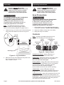
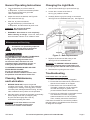
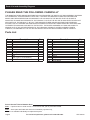
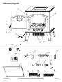
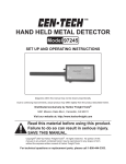
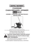
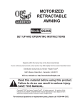
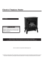
Electric Fireplace Heater
Item 68754
Read this material before using this product.
Failure to do so can result in serious injury.
SAVE THIS MANUAL.
When unpacking, make sure that the product is intact and undamaged.
If any parts are missing or broken, please call 1-800-444-3353 as soon as possible.
Visit our website at: http://www.harborfreight.com
Copyright© 2011 by Harbor Freight Tools®. All rights reserved. No portion of this manual or any artwork contained herein may be reproduced in any shape
or form without the express written consent of Harbor Freight Tools. Diagrams within this manual may not be drawn proportionally. Due to continuing
improvements, actual product may differ slightly from the product described herein. Tools required for assembly and service may not be included.
Specifications
When using electrical appliances, basic
precautions should always be followed to
reduce the risk of fire, electric shock, and
injury to persons, including the following:
Electrical Input
120V~ / 60Hz / 12.7 A
Heat Settings
750W / 1500W
1. Read all instructions before using this heater.
Light Bulb Type
40W Type B-10 Candelabra
2. This heater does not include a tip over switch.
It must be monitored at all times
during use to prevent tipping and fire,
especially if pets or children are in the house.
218805
Save This Manual
Keep this manual for the safety warnings and
precautions, assembly, operating, inspection,
maintenance and cleaning procedures. Write the
product’s serial number in the back of the manual near
the assembly diagram (or month and year of purchase
if product has no number). Keep this manual and the
receipt in a safe and dry place for future reference.
3. This heater is hot when in use. To avoid burns, do not
let bare skin touch hot surfaces. Use handles when
moving this heater. Keep combustible materials, such
as furniture, pillows, bedding, papers, clothes, and
curtains at least 3 feet (0.9 m) from the front of the
heater and keep them away from the sides and rear.
4. Extreme caution is necessary when any heater is
used by or near children or invalids and whenever
the heater is left operating and unattended.
5. Always unplug heater when not in use.
IMPORTANT
INSTRUCTIONS
In this manual, on the labeling, and all other
information provided with this product:
This is the safety alert symbol.
It is used to alert you to potential
personal injury hazards. Obey all safety
messages that follow this symbol to
avoid possible injury or death.
DANGER indicates a hazardous situation which,
if not avoided, will result in death or serious injury.
WARNING indicates a hazardous situation which,
if not avoided, could result in death or serious injury.
CAUTION, used with the safety alert symbol,
indicates a hazardous situation which, if not avoided,
could result in minor or moderate injury.
NOTICE is used to address practices
not related to personal injury.
6. Do not operate any heater with a damaged cord
or plug or after the heater malfunctions, has been
dropped or damaged in any manner. Return heater
to authorized service facility for examination,
electrical or mechanical adjustment, or repair.
7. Do not use outdoors.
8. This heater is not intended for use in bathrooms,
laundry areas and similar indoor locations.
Never locate heater where it may fall into
a bathtub or other water container.
9. Do not run cord under carpeting. Do not
cover cord with throw rugs, runners, or similar
coverings. Arrange cord away from traffic
area and where it will not be tripped over.
10. To disconnect heater, turn controls to
off, then remove plug from outlet.
11. Do not insert or allow foreign objects to enter any
ventilation or exhaust opening as this may cause
an electric shock or fire, or damage the heater.
12. To prevent a possible fire, do not block air intakes or
exhaust in any manner. Do not use on soft surfaces,
like a bed, where openings may become blocked.
13. A heater has hot and arcing or sparking parts
inside. Do not use it in areas where gasoline,
paint, or flammable liquids are used or stored.
14. Use this heater only as described in this manual.
Any other use not recommended by the manufacturer
may cause fire, electric shock, or injury to persons.
CAUTION, without the safety alert symbol, is used
to address practices not related to personal injury.
Page 2
For technical questions, please call 1-800-444-3353.
SKU 68754
15. Avoid the use of an extension cord because the
extension cord may overheat and cause a risk
of fire. However, if you have to use an extension
cord, the cord shall be 14 AWG minimum
size and rated not less than 1,524 watts.
23. WARNING: Handling the cord on this product will
expose you to lead, a chemical known to the State of
California to cause cancer, and birth defects or other
reproductive harm. Wash hands after handling.
(California Health & Safety Code § 25249.5, et seq.)
16. The output of this heater may vary and its
temperature may become intense enough to
burn exposed skin. Use of this heater is not
recommended for persons with reduced sensitivity
to heat or an inability to react to avoid burns.
24. The warnings, precautions, and instructions
discussed in this instruction manual cannot
cover all possible conditions and situations
that may occur. It must be understood by the
operator that common sense and caution are
factors which cannot be built into this product,
but must be supplied by the operator.
17. Heater service must be performed only
by an authorized service representative.
Service or maintenance performed by unqualified
personnel could result in a risk of fire or injury.
18. This double insulated heater is equipped with
a polarized plug (one blade is wider than the
other). This plug will fit in a polarized outlet
only one way. If the plug does not fit fully in
the outlet, reverse the plug. If it still does not
fit, contact a qualified electrician to install a
polarized outlet. Do not change the plug in any
way. Connect to properly grounded outlets only.
19. Do not abuse the Power Cord. Never use the
Power Cord to carry this heater or pull the Plug
from an outlet. Keep the Power Cord away from
heat, oil, or sharp edges. Replace damaged
Power Cords immediately. Damaged Power
Cords increase the risk of electric shock.
20. Disconnect the Power Cord Plug from the power
source and allow the heater to thoroughly cool
before making any adjustments, changing
accessories, or storing this heater. Such preventive
safety measures reduce the risk of burns.
21. When servicing this heater, use only identical
replacement parts. Follow instructions in the
“Inspection, Maintenance, and Cleaning” section
of this manual. Use of unauthorized parts or
failure to follow maintenance instructions may
create a risk of electric shock or injury.
22. People with pacemakers should consult their
physician(s) before use. Electromagnetic fields in
close proximity to heart pacemaker could cause
pacemaker interference or pacemaker failure.
SKU 68754
SAVE THESE
INSTRUCTIONS.
Symbology
Double Insulated
Canadian Standards Association
Underwriters Laboratories, Inc.
V~
A
Volts Alternating Current
Amperes
n0 xxxx/min. No Load Revolutions per Minute (RPM)
Read the manual before
set-up and/or use.
WARNING marking
concerning Risk of Fire.
Do not cover ventilation ducts.
Keep flammable objects away.
WARNING marking concerning
Risk of Electric Shock.
Properly connect power cord
to appropriate outlet.
For technical questions, please call 1-800-444-3353.
Page 3
Assembly
Operating Instructions
Read the ENTIRE IMPORTANT
SAFETY INFORMATION section at the
beginning of this manual including
all text under subheadings therein
before set up or use of this product.
Read the ENTIRE IMPORTANT
SAFETY INFORMATION section at the
beginning of this manual including
all text under subheadings therein
before set up or use of this product.
Area Precautions
TO PREVENT SERIOUS INJURY FROM BURNS:
Turn the Switches (21) of the heater off,
to O position, unplug the heater from
its electrical outlet, and allow it to cool
completely before assembling, moving, or
making any adjustments to the heater.
Note: For additional information regarding
the parts listed in the following pages, refer to
Parts List and Assembly Diagram on pages 6 and 7.
1. Install one Leg (1) on each corner of the Housing (3)
using 3 bolts and washers as shown in Figure A.
TO PREVENT SERIOUS INJURY FROM BURNS:
Turn the Switches (21) of the heater off,
to O position, unplug the heater from
its electrical outlet, and allow it to cool
completely before assembling, moving, or
making any adjustments to the heater.
1. Place Heater on dry, hard, stable floor away from
combustible materials. DO NOT USE ON CARPET.
2. Supervise children closely when near heater.
3. Keep pets away from heater.
Controls
bolt &
washer
Note: Controls are located inside the Door (2).
Use the Door Handle (5) to open the Door.
Leg
(1)
Turbo
Flame/Power
Switch
Switch
Thermostat
Heating
Flame
Knob
Switch
Knob
Thermostat
Housing (3)
Flame
Intensity
Turbo
Heating
Flame
Figure B: Control Panel
Figure A: Leg Installation
2. Make sure all legs are installed securely before use.
Do not use with any legs missing,
bent, crooked or loose.
Flame/Power Switch: Switch to I position to
turn the unit on and enable the flame effect.
Flame Knob: Adjusts the intensity of the flame effect
while the Flame/Power Switch is in the I position.
Does not effect the heat output.
Heating Switch: Switch to I position while the Flame/
Power Switch is in the I position to turn on the blower
and the heating element. The heating element
will turn off once the temperature triggers
the thermostat, but the fan will continue operating.
Turbo Switch: Switch to I position while both
the Flame/Power Switch and the Heating Switch are in
the I position to set the heating element to high heat.
Thermostat Knob: Adjusts the temperature at which the
heating element shuts off while the Heating Switch is in
the I position. The fan and flame effect will continue even
if the heating element shuts off. The heating element
will restart once the temperature falls.
Page 4
For technical questions, please call 1-800-444-3353.
SKU 68754
General Operating Instructions
Changing the Light Bulb
1. Turn the Switches (21) of the heater off,
to O position, to prevent accidental operation.
Then plug the heater into a grounded
120V~ electrical outlet.
1. Use the Door Handle (5) to open the Door (2).
2. Adjust the controls as desired, see Figure B.
Then close the Door (2).
3. Carefully lift the Log up far enough to access the
40W Type B-10 Candelabra Bulb (10). See Figure C.
2. Loosen the 2 screws at the front of
the Log (13) inside the heater.
3. After use, to prevent accidents,
turn the Switches (21) of the heater off,
to O position, and disconnect its power cord.
WARNING! Do not leave the heater
unattended while switched on.
4. WARNING! Allow heater to cool completely
before cleaning or storage. Once cool, clean, then
store the heater indoors out of children’s reach.
Maintenance and Servicing
Bulb
Socket (11)
Bulb (10)
screw
Procedures not specifically explained
in this manual must be performed
only by a qualified technician.
Log (13)
TO PREVENT SERIOUS INJURY FROM BURNS:
Turn the Switches (21) of the heater off,
to O position, unplug the heater from
its electrical outlet, and allow it to cool
completely before assembling, moving, or
making any adjustments to the heater.
TO PREVENT SERIOUS INJURY AND FIRE
FROM HEATER FAILURE:
Do not use damaged equipment.
If abnormal noise or vibration occurs, have
the problem corrected before further use.
Cleaning, Maintenance,
and Lubrication
1. BEFORE EACH USE, inspect the general
condition of the heater. Check for loose hardware,
misalignment or binding of moving parts, cracked
or broken parts, damaged electrical wiring, and any
other condition that may affect its safe operation.
2. Wipe the exterior surfaces of the heater occasionally
with a slightly moist cloth (not dripping wet).
Dry the case thoroughly with a soft dry
cloth before operating the heater.
WARNING! Do not allow water to run into
the interior of the heater as this could
create a fire or electric shock hazard.
SKU 68754
Figure C: Bulb Replacement
4. Replace the burned out Bulb using a new
40W Type B-10 Candelabra Bulb.
WARNING! TO PREVENT SERIOUS INJURY:
Do not use a different type of light bulb or one
with output greater than 40 watts to prevent fire.
5. Reinstall the Log using the two screws.
Troubleshooting
If the heater does not operate:
a. Make sure that the heater is plugged in.
b. Ensure that the outlet used is powered and
that the circuit breaker is not tripped.
c. Eliminate the use of an extension cord,
if possible. Otherwise, use an extension
cord with less length or greater size
(a lower AWG # indicates increased size).
d. Check for any obstruction in the heater’s vents.
If an obstruction is found, unplug the
heater and wait for it to cool completely.
Then, carefully remove the obstruction.
If the above remedies do not solve the problem,
take the heater to a qualified service technician
for diagnosis and repair.
For technical questions, please call 1-800-444-3353.
Page 5
Parts List and Assembly Diagram
PLEASE READ THE FOLLOWING CAREFULLY
THE MANUFACTURER AND/OR DISTRIBUTOR HAS PROVIDED THE PARTS LIST AND ASSEMBLY DIAGRAM
IN THIS MANUAL AS A REFERENCE TOOL ONLY. NEITHER THE MANUFACTURER OR DISTRIBUTOR
MAKES ANY REPRESENTATION OR WARRANTY OF ANY KIND TO THE BUYER THAT HE OR SHE IS
QUALIFIED TO MAKE ANY REPAIRS TO THE PRODUCT, OR THAT HE OR SHE IS QUALIFIED TO REPLACE
ANY PARTS OF THE PRODUCT. IN FACT, THE MANUFACTURER AND/OR DISTRIBUTOR EXPRESSLY
STATES THAT ALL REPAIRS AND PARTS REPLACEMENTS SHOULD BE UNDERTAKEN BY CERTIFIED AND
LICENSED TECHNICIANS, AND NOT BY THE BUYER. THE BUYER ASSUMES ALL RISK AND LIABILITY
ARISING OUT OF HIS OR HER REPAIRS TO THE ORIGINAL PRODUCT OR REPLACEMENT PARTS
THERETO, OR ARISING OUT OF HIS OR HER INSTALLATION OF REPLACEMENT PARTS THERETO.
Parts List
Part
1
2
3
4
5
6
7
8
9
10
11
Description
Leg
Door
Housing
Screen
Door Handle
Blower Box
Blower
Heating Element
Thermostat
Bulb
(40W Type B-10 Candelabra)
Bulb Socket
Qty.
1
1
1
1
1
1
1
1
1
1
1
Part
12
13
14
15
16
17
18
19
20
21
22
23
24
Description
Motor Bracket
Log
Reflector Roller
Rubber Sleeve
Reflector Motor
Bulb Socket Bracket
Power Cord
Blower Motor
Flame Controller
Switch
Temperature Controller
Knob
Circuit Board
Qty.
2
1
1
1
1
1
1
1
1
3
1
2
1
Record Product’s Serial Number Here:
Note: If product has no serial number, record month and year of purchase instead.
Note: Some parts are listed and shown for illustration purposes only,
and are not available individually as replacement parts.
Page 6
For technical questions, please call 1-800-444-3353.
SKU 68754
Assembly Diagram
3
13
5
2
18
23
1
20
21
22
16
15
14
12
24
10
11
17
4
6
SKU 68754
7
19
For technical questions, please call 1-800-444-3353.
9
8
Page 7
Limited 90 Day Warranty
Harbor Freight Tools Co. makes every effort to assure
that its products meet high quality and durability
standards, and warrants to the original purchaser
that this product is free from defects in materials and
workmanship for the period of 90 days from the date
of purchase. This warranty does not apply to damage
due directly or indirectly, to misuse, abuse, negligence
or accidents, repairs or alterations outside our facilities,
criminal activity, improper installation, normal wear and
tear, or to lack of maintenance. We shall in no event
be liable for death, injuries to persons or property, or
for incidental, contingent, special or consequential
damages arising from the use of our product. Some
states do not allow the exclusion or limitation of incidental
or consequential damages, so the above limitation of
exclusion may not apply to you. THIS WARRANTY IS
EXPRESSLY IN LIEU OF ALL OTHER WARRANTIES,
EXPRESS OR IMPLIED, INCLUDING THE
WARRANTIES OF MERCHANTABILITY AND FITNESS.
To take advantage of this warranty, the product or part
must be returned to us with transportation charges
prepaid. Proof of purchase date and an explanation
of the complaint must accompany the merchandise. If
our inspection verifies the defect, we will either repair
or replace the product at our election or we may elect
to refund the purchase price if we cannot readily and
quickly provide you with a replacement. We will return
repaired products at our expense, but if we determine
there is no defect, or that the defect resulted from
causes not within the scope of our warranty, then
you must bear the cost of returning the product.
This warranty gives you specific legal rights and you may
also have other rights which vary from state to state.
3491 Mission Oaks Blvd. • PO Box 6009
Camarillo, CA 93011 • (800) 444-3353
3491 Mission Oaks Blvd. • PO Box 6009 • Camarillo, CA 93011 • (800) 444-3353