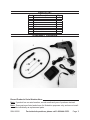
1
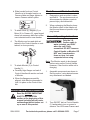
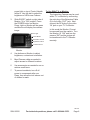
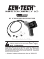
INSPECTION CAMERA 2.4” lcd
66550
Set up and Operating Instructions
Visit our website at: http://www.harborfreight.com
Read this material before using this product.
Failure to do so can result in serious injury.
Save this manual.
Copyright© 2008 by Harbor Freight Tools®. All rights reserved. No portion of this manual or any artwork
contained herein may be reproduced in any shape or form without the express written consent of
Harbor Freight Tools. Diagrams within this manual may not be drawn proportionally. Due to continuing
improvements, actual product may differ slightly from the product described herein. Tools required for
assembly and service may not be included.
For technical questions or replacement parts, please call 1-800-444-3353.
Revised Manual 09k
NOTICE is used to
address practices
not related to personal injury.
Save This Manual
Keep this manual for the safety warnings and precautions, assembly, operating, inspection, maintenance and cleaning
procedures. Write the product’s serial
number in the back of the manual near the
assembly diagram (or month and year of
purchase if product has no number). Keep
this manual and the receipt in a safe and
dry place for future reference.
CAUTION, without
the safety alert
symbol, is used to address
practices not related to
personal injury.
General Power Tool Safety
Warnings
Important SAFETY
Information
WARNING Read all safety
warnings and instructions.
Failure to follow the warnings and
instructions may result in electric
shock, fire and/or serious injury.
Save all warnings and
instructions for future reference.
Work area safety
In this manual, on the labeling,
and all other information provided with this product:
This is the safety alert
symbol. It is used to alert
you to potential personal
injury hazards. Obey all
safety messages that
follow this symbol to avoid
possible injury or death.
a.Keep work area clean and well lit.
Cluttered or dark areas invite accidents.
b.Do not operate power tools in
explosive atmospheres, such as in
the presence of flammable liquids,
gases or dust. Power tools create
sparks which may ignite the dust or
fumes.
DANGER indicates
a hazardous
situation which, if not
avoided, will result in death or
serious injury.
WARNING
indicates a
hazardous situation which, if
not avoided, could result in
death or serious injury.
c.Keep children and bystanders
away while operating a power tool.
Distractions can cause you to lose
control.
CAUTION, used
with the safety
alert symbol, indicates a
hazardous situation which, if
not avoided, could result in
minor or moderate injury.
SKU 66550
2.
Electrical safety
a.Power tool plugs must match the
outlet. Never modify the plug in
any way. Do not use any adapter
plugs with grounded power tools.
Unmodified plugs and matching outlets will reduce risk of electric shock.
b.Avoid body contact with grounded
surfaces such as pipes, radiators,
For technical questions, please call 1-800-444-3353.
Page 2
ranges and refrigerators. There is
an increased risk of electric shock if
your body is grounded.
c.Do not expose power tools to rain
or wet conditions. Water entering
a power tool will increase the risk of
electric shock.
3.
Personal safety
a.Stay alert, watch what you are doing and use common sense when
operating a power tool. Do not use
a power tool while you are tired
or under the influence of drugs,
alcohol or medication. A moment
of inattention while operating power
tools may result in serious personal
injury.
b.Use personal protective equipment. Always wear eye protection.
Safety equipment such as dust mask,
non-skid safety shoes, hard hat, or
hearing protection used for appropriate conditions will reduce personal
injuries.
c.Prevent unintentional starting.
Ensure the switch is in the off-position before connecting to power
source and/or battery pack, picking up or carrying the tool. Carrying power tools with your finger on
the switch or energizing power tools
that have the switch on invites accidents.
d.Do not overreach. Keep proper
footing and balance at all times.
This enables better control of the
power tool in unexpected situations.
e.Only use safety equipment that
has been approved by an appropriate standards agency. Unapproved
safety equipment may not provide
adequate protection. Eye protection
SKU 66550
must be ANSI-approved and breathing protection must be NIOSH-approved for the specific hazards in the
work area.
4.
Power tool use and care
a.Do not force the power tool. Use
the correct power tool for your application. The correct power tool will
do the job better and safer at the rate
for which it was designed.
b.Disconnect the plug from the
power source and/or the battery
pack from the power tool before
making any adjustments, changing accessories, or storing power
tools. Such preventive safety measures reduce the risk of starting the
power tool accidentally.
c.Store idle power tools out of the
reach of children and do not allow
persons unfamiliar with the power
tool or these instructions to operate the power tool. Power tools are
dangerous in the hands of untrained
users.
d.Maintain power tools. Check for
misalignment or binding of moving
parts, breakage of parts and any
other condition that may affect the
power tool’s operation. If damaged, have the power tool repaired
before use. Many accidents are
caused by poorly maintained power
tools.
e.Use the Camera and accessories
in accordance with these instructions, taking into account the
working conditions and the work
to be performed. Use of the Camera for operations different from those
intended could result in a hazardous
situation.
For technical questions, please call 1-800-444-3353.
Page 3
5.
Battery tool use and care
a.Recharge only with the charger
specified by the manufacturer. A
charger that is suitable for one type of
battery pack may create a risk of fire
when used with another battery pack.
b.Use the Camera only with specifically designated battery packs.
Use of any other battery packs may
create a risk of injury and fire.
c.When battery pack is not in use,
keep it away from other metal objects, like paper clips, coins, keys,
nails, screws or other small metal
objects, that can make a connection from one terminal to another.
Shorting the battery terminals together may cause burns or a fire.
d.Under abusive conditions, liquid
may be ejected from the battery;
avoid contact. If contact accidentally occurs, flush with water. If
liquid contacts eyes, additionally
seek medical help. Liquid ejected
from the battery may cause irritation
or burns.
6.
Service
a.Have your Camera serviced by a
qualified repair person using only
identical replacement parts. This
will ensure that the safety of the
power tool is maintained.
Camera Safety Warnings
1.
Do not use for medical purposes.
2.
If inspecting gun, unload and engage
safety before inspection.
3.
If inspecting engine, turn off and disable before inspection.
SKU 66550
4.
Wear ANSI-approved safety goggles
during use.
5.
Position batteries in proper polarity
and do not install batteries of different types, charge levels, or capacities
together.
6.
Maintain labels and nameplates on
the Camera. These carry important
safety information. If unreadable or
missing, contact Harbor Freight Tools
for a replacement.
7.
Avoid unintentional starting. Prepare
to begin work before turning on the
Camera.
8.
Do not leave the tool unattended
when it is plugged into an electrical
outlet. Turn off the tool, and unplug it
from its electrical outlet before leaving.
9.
This product is not a toy. Keep it out
of reach of children.
10. People with pacemakers should
consult their physician(s) before use.
Electromagnetic fields in close proximity to heart pacemaker could cause
pacemaker interference or pacemaker failure. In addition, people with
pacemakers should:
• Avoid operating alone.
• Do not use with power switch locked
on.
• Properly maintain and inspect to
avoid electrical shock.
• Any power cord must be properly
grounded. Ground Fault Circuit Interrupter (GFCI) should also be implemented – it prevents sustained electrical shock.
11. Handling the cord on this product
will expose you to lead, a chemical
known to the State of California to
For technical questions, please call 1-800-444-3353.
Page 4
cause cancer, and birth defects or
other reproductive harm. Wash hands
after handling. (California Health &
Safety Code § 25249.5, et seq.)
12. The warnings, precautions, and instructions discussed in this instruction
manual cannot cover all possible conditions and situations that may occur.
It must be understood by the operator
that common sense and caution are
factors which cannot be built into this
product, but must be supplied by the
operator.
13. This device complies with part 15 of
the FCC Rules. Operation is subject
to the following two conditions: (1)
This device may not cause harmful
interference, and (2) this device must
accept any interference received,
including interference that may cause
undesired operation.
Save these
instructions.
SKU 66550
For technical questions, please call 1-800-444-3353.
Page 5
Specifications
including HVAC inspection, automotive/
boat/aircraft inspection, cable routing, etc.
CAMERA
Total Pixels
704x576 (PAL);
712x486 (NTSC)
Modulation Type
FM
Bandwidth
18MHz
Power Supply
4 AA batteries
To prevent
injury from
accidental operation:
Turn the Power Switch on the
Control Handle and Monitor to
“OFF” position and unplug
the Adaptor from its electrical
outlet before performing any
adjustments, inspection,
maintenance, or cleaning
procedures.
MONITOR
LCD Screen Type
2.36”TFT-LCD
Effective Pixels
480x240
Electrical Input
8-24 VDC / 450mA
Adapter Input
120 V~ / 60 Hz
Operating Temperature +14°F~+122°F
Operating Humidity
15~85%RH
Note: For additional information regarding
the parts listed in the following pages,
refer to the Parts Diagram near the
end of this manual.
Unpacking
When unpacking, make sure that the
item is intact and undamaged. If any parts
are missing or broken, please call Harbor
Freight Tools at the number shown on the
cover of this manual as soon as possible.
Inspection Camera Set Up
1.
a.Remove screw and cover on bottom
of Control Handle (1).
Instructions for
putting into use
b.Slide Battery Compartment out of
Control Handle (1) and insert four AA
batteries.
Read the entire Important
Safety Information
section at the beginning of this
manual including all text under
subheadings therein before set
up or use of this product.
c. Reinstall battery compartment and
cover. Secure with screw.
Keyed ends
Functions
This mini water resistant camera with
3 ft. flexible tubing can be used to view
hard to reach locations while displaying
real-time video images on the 2.4” Monitor.
May be used for a variety of applications
SKU 66550
To install Batteries:
Control
Handle
Camera
Knurled Knob
2.
To attach Camera (2) to Control
Handle (1):
a.Align keyed ends of Control Handle
with cable end of Camera.
For technical questions, please call 1-800-444-3353.
Page 6
b.Slide knurled knob on Control
Handle up to threaded section on
Camera cable and finger tighten to
secure Camera cable in place.
3.
4.
5.
To attach Hook (4), Magnet (5), or
Mirror (6) to Camera (2), open hinged
sleeve on accessory and clip in place
over indented section near camera.
Work Piece and Work Area Set Up
1.
Designate a work area that is clean
and well-lit. The work area must not
allow access by children or pets to
prevent injury and distraction.
2.
When recharging the Monitor, keep
the Monitor close to the Adaptor so
that the cord does not present a tripping hazard.
General Operating Instructions
Only the 3 ft.
Camera cable is
water resistant, and ONLY
when the unit if fully
assembled. DO NOT immerse
Control Handle or Monitor. DO
NOT use if condensation
forms on lens. Let water
evaporate before using.
The Monitor can be used while attached to the Control Handle or unattached, in close proximity.
To attach Monitor (3) to Control
Handle (1):
a.Carefully align flanges on back of
Control Handle with section on back
of Monitor.
Note: The Monitor needs to be charged
before using on the Control Handle.
However, it can function while unit is
charging.
1.
Assemble components as shown in
Set Up section, using desired accessory attachment as needed.
b.When the flanges are carefully
aligned, slide Monitor downward to
lock it in place on the Control Handle.
Operating Instructions
Read the entire Important
Safety Information
section at the beginning of this
manual including all text under
subheadings therein before set
up or use of this product.
SKU 66550
ON/OFF Dial
2.
Turn ON/OFF dial on Control Handle
(1) backwards to turn on power to
camera. Two LEDs near Camera and
For technical questions, please call 1-800-444-3353.
Page 7
power light on top of Control Handle
will be lit. Use this dial to adjust the
brightness of LEDs near Camera.
3.
Slide ON/OFF switch on right side of
Monitor (3) to “ON” position. Press
the POWER button on Monitor.
Power Light on Monitor will be green
and Monitor will display live camera
image.
Power Light
Power Button
Orientation Control
Brightness Control
To Use With T.V. or Monitor
The Inspection Camera may be used
with a T.V. or Monitor by connecting
the mini plug of the Extension Cable
(9) to the video “OUT” jack. Next
connect the RCA plug to the video
“IN’ jack on your T.V. or Monitor.
In this mode the Monitor (3) must
be removed from the camera. Turn
the Monitor (3) “ON” and turn the
camera “ON” and the picture will
be transferred to the T.V./Monitor
remotely.
Contrast Control
Monitor
4.
Use buttons on Monitor to adjust
brightness, contrast and orientation.
5.
Bend Camera cable as needed to
adjust access to different locations.
6.
Use accessories as needed to see or
retrieve small items.
7.
To prevent accidents, turn off all
power to components after use.
Clean, then store the tool indoors out
of children’s reach.
REV 09k
SKU 66550
For technical questions, please call 1-800-444-3353.
Page 8
Maintenance And
Servicing
Procedures not specifically
explained in this manual
must be performed only by a
qualified technician.
To prevent
injury from
accidental operation:
Turn the Power Switch of the
Monitor to its “OFF” position
and unplug the adaptor from
its electrical outlet before
performing any inspection,
maintenance, or cleaning
procedures.
2.
After Use, clean external surfaces
of the tool with clean cloth.
3.
WARNING! If the supply cord of
the adaptor is damaged, it must be
replaced only by a qualified service technician.
Charging Monitor
To prevent injury from
tool failure:
Do not use damaged
equipment. If abnormal noise
or vibration occurs, have the
problem corrected before
further use.
1.
BEFORE EACH USE, inspect the
general condition of the tool. Check
for loose screws, misalignment or
binding of moving parts, cracked or
broken parts, damaged electrical wiring, and any other condition that may
affect its safe operation.
Adapter Cable (7)
Adapter (8)
Monitor (3)
1.
Plug male end of Adapter Cable (7)
into Monitor (3) and female end onto
Adapter (8) plug. Plug adapter (8)
into wall socket.
2.
Power light will be red, indicating unit
is charging. With the monitor attached to the control handle, unit can
still be used while monitor is charging, but only when attached to the
handle.
3.
When unit is fully charged, red light
will turn off.
4.
Fully charged monitor will work continuously for approximately 5 hours.
REV 09f
SKU 66550
For technical questions, please call 1-800-444-3353.
Page 9
Troubleshooting
Problem
Possible Causes
Tool will not start.
1. Monitor not charged.
2. Batteries need changing.
1. Cable not attached properly.
2. Adapter not connected to
power.
Monitor will not
charge.
Image too dark or
light.
1. LEDs near camera need
adjustment.
2. Monitor display needs
adjustment.
Likely Solutions
1. Charge Monitor.
2. Replace batteries in Control Handle.
1. Make sure Adapter Cable is connected
between Monitor and Adapter.
2. Make sure Adapter is securely plugged into
wall socket.
1. Use dial on Control Handle to adjust
brightness of LEDs.
2. Use Contrast and Brightness buttons on
Monitor to adjust image.
Follow all safety precautions whenever diagnosing or servicing the
tool. Disconnect power supply before service.
PLEASE READ THE FOLLOWING CAREFULLY
The manufacturer and/or distributor has provided the parts list and assembly
diagram in this manual as a reference tool only. Neither the manufacturer or
distributor makes any representation or warranty of any kind to the buyer that
he or she is qualified to make any repairs to the product, or that he or she is
qualified to replace any parts of the product. In fact, the manufacturer and/or
distributor expressly states that all repairs and parts replacements should be
undertaken by certified and licensed technicians, and not by the buyer. The buyer
assumes all risk and liability arising out of his or her repairs to the original
product or replacement parts thereto, or arising out of his or her installation
of replacement parts thereto.
SKU 66550
For technical questions, please call 1-800-444-3353.
Page 10
Parts List
Part
1
2
3
4
5
6
7
8
9
Description
Control Handle
Mini Camera with Cable
Monitor
Hook
Magnet
Mirror
Adapter Cable
Adapter
Extension Cable
Qty.
1
1
1
1
1
1
1
1
1
ASSEMBLY DIAGRAM
1
2
8
6
5
4
9
3
7
Record Product’s Serial Number Here:
Note: If product has no serial number, record month and year of purchase instead.
Note: Some parts are listed and shown for illustration purposes only, and are not available individually as replacement parts.
SKU 66550
For technical questions, please call 1-800-444-3353.
Page 11
LIMITED 90 DAY WARRANTY
Harbor Freight Tools Co. makes every effort to assure that its products meet high
quality and durability standards, and warrants to the original purchaser that this product
is free from defects in materials and workmanship for the period of 90 days from the date
of purchase. This warranty does not apply to damage due directly or indirectly, to misuse,
abuse, negligence or accidents, repairs or alterations outside our facilities, criminal activity,
improper installation, normal wear and tear, or to lack of maintenance. We shall in no event
be liable for death, injuries to persons or property, or for incidental, contingent, special
or consequential damages arising from the use of our product. Some states do not allow
the exclusion or limitation of incidental or consequential damages, so the above limitation
of exclusion may not apply to you. This warranty is expressly in lieu of all
other warranties, express or implied, including the warranties of
merchantability and fitness.
To take advantage of this warranty, the product or part must be returned to us with
transportation charges prepaid. Proof of purchase date and an explanation of the complaint
must accompany the merchandise. If our inspection verifies the defect, we will either
repair or replace the product at our election or we may elect to refund the purchase price
if we cannot readily and quickly provide you with a replacement. We will return repaired
products at our expense, but if we determine there is no defect, or that the defect resulted
from causes not within the scope of our warranty, then you must bear the cost of returning
the product.
This warranty gives you specific legal rights and you may also have other rights which
vary from state to state.
3491 Mission Oaks Blvd. • PO Box 6009 • Camarillo, CA 93011 • (800) 444-3353
SKU 66550
For technical questions, please call 1-800-444-3353.
Page 12