1
®
10" TABLE SAW
Model 46813
ASSEMBLY AND
OPERATING INFORMATION
®
3491 Mission Oaks Blvd., Camarillo, CA 93011
Visit our Web site at http://www.harborfreight.com
Copyright 2002 by Harbor Freight Tools®. All rights reserved. No portion of this
manual or any artwork contained herein may be reproduced in any shape or form
without the express written consent of Harbor Freight Tools.
For technical questions please call 1-800-444-3353
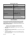
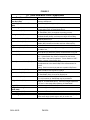
SPECIFICATIONS TABLE
! "# $% &'(
7&# $% :5$(
7&;:%<$ <$$! ='(
&$# =?@'
5 IJ
5 I%<$! Q@'(
5 #:! QI%°(
;! QI
=
R 'X <$
=
<# $
#I$$<
7$$$
I$$
;:
)*+-/ 5*/#5+-/
+-/ 5*/#
+-/
)->/
/# 5)->/+7:
I&'7 )
'
/LQ='+)->/
;:='
/
)/
°+)°%LQ! J(
°)°°)°°
;:! LQ
)° V++$° V
<J'X&
/7$/LQ/7$)/
;:
+-/ 5/L5+-/
#:;$+-/! #
- ! ' :
) 5YJ
IR$ @=
Z ')='?[<
\$'
SAVE THIS MANUAL
You will need this manual for the safety warnings and precautions, assembly,
operating, inspection, maintenance, and cleaning procedures, parts list and
assembly diagrams. Keep your invoice with this manual. Write the invoice
number on the inside of the front cover. Keep this manual and invoice in a safe
and dry place for future reference.
GENERAL SAFETY WARNINGS AND PRECAUTIONS
1.
KEEP WORK AREA CLEAN AND DRY. Cluttered, damp or wet work areas
invite injuries.
2.
KEEP CHILDREN AWAY FROM WORK AREA. Do not allow children to handle
this product.
3.
STORE IDLE EQUIPMENT. When not in use, tools and equipment should be
stored in a dry location to inhibit rust. Always lock up tools and equipment and
keep out of reach of children.
SKU 46813
PAGE 2
4.
DO NOT USE THIS PRODUCT IF UNDER THE INFLUENCE OF ALCOHOL OR
DRUGS. Read warning labels on prescriptions to determine if your judgment or
reflexes are impaired while taking drugs. If there is any doubt, do not attempt to
use this product.
5.
USE EYE, HEARING, AND BREATHING PROTECTION. Wear ANSI approved
safety impact eyeglasses, hearing protectors, and dust masks or respirator when
using this product. ANSI approved safety impact eyeglasses, hearing protectors,
dust masks and respirators are available from Harbor Freight Tools.
6.
DRESS SAFELY. Non-skid footwear or safety shoes should be used when
working with this product. Do not wear loose clothing or jewelry as they can
become caught in moving parts. Wear a protective hair covering to prevent long
hair from becoming caught in moving parts. If wearing a long-sleeve shirt, roll
sleeves up above elbows.
7.
INDUSTRIAL APPLICATIONS MUST FOLLOW OSHA REQUIREMENTS.
8.
DO NOT OVERREACH. Keep proper footing and balance at all times to prevent
tripping, falling, back injury, etcetera.
9.
STAY ALERT. Watch what you are doing at all times. Use common sense. Do
not use this product when you are tired or distracted from the job at hand.
10.
CHECK FOR DAMAGED PARTS. Before using this product, carefully check that
it will operate properly and perform its intended function. Check for damaged
parts and any other conditions that may affect the operation of this product.
Replace or repair damaged or worn parts immediately.
11.
REPLACEMENT PARTS AND ACCESSORIES. When servicing, use only
identical replacement parts. Only use accessories intended for use with this
product. Approved accessories are available from Harbor Freight Tools.
12.
MAINTAIN THIS PRODUCT WITH CARE. Keep this tool clean and dry, and
keep Saw Blades clean and sharp for better and safer performance.
13.
MAINTENANCE: For your safety, service and maintenance should be performed
regularly by a qualified technician.
14.
USE THE RIGHT PRODUCT FOR THE RIGHT JOB. There are certain
applications for which this product was designed. Do not use small equipment,
tools or attachments to do the work of larger industrial equipment, tools or
attachments. Do not use this product for a purpose for which it was not intended.
SKU 46813
PAGE 3
SPECIFIC PRODUCT WARNINGS AND PRECAUTIONS
1.
GROUND THIS PRODUCT. The electrical power cord for this product is
equipped with a grounded 3-Prong Plug. Never remove the grounding prong or
modify the Plug in any way. Do not use adapter plugs with this product. To
comply with the National Electric Code, and to provide additional protection from
the risk of electrical shock, the Table Saw should only be connected to a 110 Volt,
3 prong electrical outlet that is protected by a Ground Fault Circuit Interrupter
(GFCI).
2.
MAKE SURE THE POWER SWITCH (part #8E) IS IN THE “OFF” POSITION
BEFORE PLUGGING IN THE POWER CORD (part #8F).
3.
DO NOT ABUSE THE POWER CORD. Do not use the Power Cord (part #8F) to
pull the 3-prong plug from a power outlet. Keep cord away from heat, oil, sharp
edges, and moving parts. Replace damaged cord immediately. Route the power
cord safely. Protect it from being damaged by other equipment in the shop. Do
not route the cord where it can be walked on or tripped over.
4.
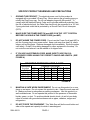
IF YOU USE AN EXTENSION CORD, MAKE SURE TO USE ONLY UL
APPROVED CORDS HAVING THE CORRECT GAUGE AND LENGTH. (SEE
FIGURE A.)
+)
)+>
>+
+)
)+
)
5$I$'L;:
)
*)
)
+
+
+
+
+
+
+
+
FIGURE A
5.
MAINTAIN A SAFE WORK ENVIRONMENT. Do not use this product in or near
damp or wet areas. Do not expose this product to rain. Keep the work area well
lit. Make sure there is adequate surrounding workspace. Use this product in a
well ventilated area. Do not operate this product in the presence of flammable
liquids, gases, or dust. To avoid accidental electric shock, do not let your body
come in contact with grounded surfaces such as pipes, radiators, ranges and
refrigerators.
6.
DO NOT FORCE THE EQUIPMENT. This Table Saw will do the work better and
safer at the speed and capacity for which it was designed.
SKU 46813
PAGE 4
7.
KEEP ALL GUARDS IN PLACE AND IN WORKING ORDER.
8.
REMOVE ALL ADJUSTING WRENCHES FROM THE TABLE SAW BEFORE
TURNING IT ON.
9.
AVOID UNINTENTIONAL STARTING. Make sure you are prepared to begin
work before turning the Power Switch (part #8E) “ON”.
10.
DO NOT USE THIS TOOL FOR CUTTING METALS OR BRITTLE MATERIALS.
Do not cut dangerous materials, such as asbestos that can cause harmful dust or
vapors.
11.
ALLOW THE SAW BLADE (part #14-I) TO SPIN UP TO FULL SPEED BEFORE
FEEDING WOOD INTO IT. When turning it off, allow the Saw Blade to spin
down and stop on its own. Do not press against the Saw Blade to stop it.
12.
Caution: Never pass hands directly over the Saw Blade (part #14-I) when
cutting the workpiece. Always push the workpiece into the Saw Blade, using an
auxiliary handle or push stick (not provided).
13.
DO NOT FORCE THE MATERIAL INTO THE SAW BLADE (part #14-I) WHEN
CUTTING. Apply moderate pressure, allowing the Saw Blade to cut without
being forced.
14.
NEVER ATTEMPT TO REMOVE MATERIAL STUCK IN THE MOVING PARTS
OF THE TABLE SAW WHILE IT IS PLUGGED IN AND RUNNING.
15.
TURN OFF THE TABLE SAW IF THE WOODSTOCK IS TO BE BACKED OUT
OF AN UNCOMPLETED CUT.
16.
ALWAYS KEEP HANDS AND FINGERS AWAY FROM THE SAW BLADE (part
#14-I). Use an auxiliary handle or push stick (not provided) at all times.
17.
MAKE SURE THE WORKPIECE IS FREE FROM NAILS AND ANY OTHER
FOREIGN OBJECTS WHICH COULD DAMAGE THE SAW BLADE (part #14-I).
18.
ALWAYS FEED THE WORKPIECE INTO THE SAW BLADE (part #14-I) AND
AGAINST ITS ROTATION.
19.
WARNING: When replacing the Saw Blade (part #14-I), ALWAYS replace it with
a Saw Blade rated at least 3,400 RPM to prevent possible injury.
20.
REDUCE THE RISK OF KICKBACK. Kickback is caused when the Saw Blade
(part #14-I) becomes pinched, miss-aligned, or twisted during the cutting
process, resulting in personal injury and/or damage to the tool.
SKU 46813
PAGE 5
20.
(Continued) To avoid kickback, keep a firm grip on the workpiece at all times.
Support overhanging work pieces; as the work piece is cut and weakens it will
sag, causing a pinched Saw Blade. Push the workpiece slower than normal
when cutting through knots, pressure treated and green lumber. Do not attempt
to force the workpiece back on the cut line if the cut begins to go off line. Make
sure to set the depth adjustment of the Table Saw so that one saw tooth of the
Saw Blade projects below the work piece.
21.
MAKE SURE THE WORKPIECE IS SUPPORTED AT ALL TIMES DURING
OPERATION. Use a Roller Stand (not provided) with a larger workpiece if
necessary.
22.
MAINTAIN CONTROL OF THE WORKPIECE AT ALL TIMES. Never allow the
workpiece to rest on the moving Saw Blade (part #14-I) without safely holding on
to the workpiece.
23.
BEFORE TRYING NEW OR COMPLICATED TECHNIQUES, STUDY THE
PROCEDURE, AND PRACTICE WITH SCRAP WOOD.
24.
ALWAYS DISCONNECT THE TABLE SAW FROM ITS ELECTRICAL SUPPLY
SOURCE BEFORE PERFORMING ANY SERVICES OR MAINTENANCE. Turn
off and unplug the Table Saw when leaving the work area, moving the tool from
one location to another, changing Saw Blades (part #14-I), cleaning sawdust
from the unit, etcetera.
25.
NEVER USE UNAUTHORIZED ACCESSORIES. Never install unauthorized
accessories such as shaper cutters, wire wheels, grinding wheels or sanding
products.
26.
WARNING: Some dust created by power sanding, sawing, grinding, drilling, and
other construction activities, contain chemicals known (to the State of California)
to cause cancer, birth defects or other reproductive harm. Some examples of
these chemicals are: lead from lead-based paints, crystalline silica from bricks
and cement or other masonry products, arsenic and chromium from chemically
treated lumber. Your risk from these exposures varies, depending on how often
you do this type of work. To reduce your exposure to these chemicals; work in a
well ventilated area, and work with approved safety equipment, such as those
dust masks that are specially designed to filter out microscopic particles.
(California Health & Safety Code 25249.5, et seq.)
27.
WARNING: People with pacemakers should consult with their physician(s)
before using this product. Operation of equipment in close proximity to a heart
pacemaker could cause interference or failure of the pacemaker.
SKU 46813
PAGE 6
UNPACKING
When unpacking, check to make sure all parts shown on the Parts Lists (pages 27
through 29) are included. If any parts are missing or broken, please call Harbor Freight
Tools at the number shown on the cover of this manual as soon as possible.
PRODUCT OVERVIEW
1.
NOTE: Prior to operating the 10" Table Saw, make sure you familiarize yourself
with the main parts components and their functions. (See Figures B, C, and
Assy. Diagrams A through I.)
RIVING
KNIFE
(#6D)
MITER
GAUGE
GROOVE
EXTENSION
TABLE
(#5H)
BLADE
GUARD
(#10D)
10” SAW BLADE
(#14-I)
ANTI-KICKBACK
PAWL (#2D)
ALIGN-A-CUT
INSERT (#4H)
RIP FENCE
(#10C)
SCALE (#6H)
REAR
RAIL (#3H)
MITER GAUGE (#4A)
BEVEL
HANDLE
(#5G)
BASE (#1G)
BEVEL
SCALE
(#10G)
HEIGHT
HANDLE
(#5G)
FRONT RAIL
(#7H)
SWITCH
(#8E)
FINE
ADJUSTMENT
KNOB (#30C)
RIP FENCE
HANDLE
(#37C)
END BRACE
(#6B)
SIDE BRACE
(#7B)
LEG (#4B)
LONG LEG
BRACE (#10B)
SHORT LEG
BRACE (#9B)
LEVELING FOOT (#1B)
FIGURE B
SKU 46813
PAGE 7
FIGURE C
!$%
%&%'
*2'79;<
2'=9;
>?@[\]
2'^9;
$+[_
`j+j2';
_[k?2'x;
zk{{%!2'|;
!`j2'}z;
[zz+2'}9;
*2';
2'x9;
!\2'~;
*j+k2'=;
*9j2'=7;
`_9j2'^;
`_2';
9[\9j2'^;
>[2'}`;
>[@\>[`
2'`<'`;
>_[*2'`;
`2';
$+[2};
SKU 46813
*+
$"'$Q$:
<%I(
';?$V
$"'$Q$;?$V%$"&(
7:Z;%(':;$$"$'
$&$:'$Q:/=?@'%+R(
?JV:@'Z''$?$":
/=?@'%+R(:$;:$:;$
L$''J&:':/=?@'%+R(=$
:@'Z'%#('V';Q$&';
#;'$:':$':?$V$"XJ
:$'VV&V$
/=?@''X'?:@"'';:
'%)Z($'$:''Q$$Q@%Z(
J&V'$'$$$Q?$:?$V
Z':?$V';:;$'X
Q$?':$Q
L$'$:<$
%*($&$?:
<%I($'
L$'$:<$
%*($"'$?$:7&
=?$?=?:YJ&'$:=?:
&Q$7&=?&$'7$$V=?:/!<</
$$$"$?=?:YJ
L$'$:Q$$Q:
<%I($V
Q'X$:''
<Q$
;:$:Y$&'$$$
<
LQ'$
<
L$?'$$V
<
L$'$;:'$Q@%Z(7'$:
/=?@'%+R(Q$&"%;'(
L$'$Q$$Q@%Z(R'5;
%°+)°(?::/=?@'J&$$'
L$'$Q$$Q@%Z(7'$$?$
;:$Q/=?@'%+R(5:;:'X
)/°$'?:;/=?@'
$"'$Q$7&=?
$"'$Q$L;%@(
7$"7&=?$:Q$$Q
I$$$)/?'5\/'
;?$VQ$=R'$%(
:$?5;%°+\°;:$Q(Q$
PAGE 8
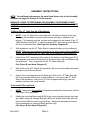
ASSEMBLY INSTRUCTIONS
NOTE: For additional references to the parts listed below, refer to the Assembly
Diagrams on pages 29 through 37 of this manual.
WARNING! PRIOR TO PERFORMING ANY ASSEMBLY PROCEDURES, MAKE
SURE THE 10" TABLE SAW IS DISCONNECTED FROM ITS ELECTRICAL POWER
SOURCE.
To Mount The 10" Table Saw On A Workbench:
1.
NOTE: If the 10" Table Saw is mounted onto a workbench instead of the Leg
Assembly, the workbench surface must have an opening for sawdust to fall
through. This opening must be as large as the opening in the bottom of the 10"
Table Saw Base (part #1G). A minimum height of 36" from the top of the Base to
the floor is recommended. (See Figure B, and Assy. Diagram G.)
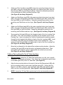
2.
With assistance, set the 10" Table Saw in a desired location on the workbench.
NOTE: Make sure the workbench provides a flat, level, sturdy surface capable of
supporting the weight of the 10" Table Saw, tool accessories, and workpieces.
3.
Use the four 5/16" mounting holes located at the bottom of the Base (part #1G))
as a template, and mark the two points at which four holes will be drilled through
the workbench. Then, temporarily set the 10" Table Saw aside.
(See Figure B, and Assy. Diagram G.)
4.
With a drill and a 5/16” drill bit (not provided), drill four mounting holes downward
through the top of the workbench.
5.
Align the four mounting holes at the Base (part #1G) of the 10" Table Saw with
the four previously drilled holes in the workbench. Then secure the 10" Table
Saw to the workbench, using four 5/16” bolts of appropriate length, two lock
washers, and two nuts (not provided).
To Assemble The Leg Stand:
1.
NOTE: Temporarily finger tighten all hardware mentioned in this section until the
Leg Stand is fully assembled.
2.
Attach one Long Leg Brace (part #10B) to the lower mounting holes in two Legs
(part #4B), using one Carriage Bolt (part #5B), one Washer (part #3B), and one
Hex Nut (part #2B) for each Long Leg Brace. Repeat the assembly procedure
for the remaining one Long Leg Brace and two Legs.
(See Figure B, and Assy. Diagram B.)
SKU 46813
PAGE 9
3.
Attach one Short Leg Brace (part #9B) to the lower mounting holes in two Legs
(part #4B), using one Carriage Bolt (part #5B), one Washer (part #3B), and one
Hex Nut (part #2B) for each Short Leg Brace. Repeat the assembly procedure
for the remaining one Short Leg Brace and two Legs.
(See Figure B, and Assy. Diagram B.)
4.
Attach one Side Brace (part #7B) to the upper mounting holes in two Legs (part
#4B), using two Carriage Bolts (part #5B), two Washers (part #3B), and two Hex
Nuts (part #2B) for each Side Brace. Repeat the assembly procedure for the
remaining one Side Brace and two Legs. (See Figure B, and Assy. Diagram
B.)
5.
Attach one End Brace (part #6B) to the upper mounting holes in two Legs (part
#4B), using two Carriage Bolts (part #5B), two Washers (part #3B), and two Hex
Nuts (part #2B) for each End Brace. Repeat the assembly procedure for the
remaining one End Brace and two Legs. (See Figure B, and Assy. Diagram B.)
6.
Screw one Hex Nut (part #2B) onto the threads of each of the four Leveling Feet
(part #1B). Then, insert one Washer (part #3B) onto the threads of each of the
Leveling Feet. Insert a Leveling Foot, with its threaded portion pointing upward,
through the hole located at the bottom of each of the four Legs (part #4B). Insert
one Washer (part #3B) onto the threads of each of the Leveling Feet. Then,
screw one Hex Nut (part #2B) onto the threads of each of the four Leveling Feet.
(See Figure B, and Assy. Diagram B.)
7.
Move the Leg Assembly to the desired floor surface working location. Adjust the
Leveling Feet (part #1B) so that the entire Leg Assembly stands level. Then,
firmly tighten all hardware, using an appropriate size wrench (not provided).
(See Figure B, and Assy. Diagram B.)
To Mount The Leg Stand On The 10" Table Saw Base:
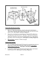
1.
With assistance, place the 10" Table Saw upside down on a flat, level, smooth
surface (i.e., cardboard) on the floor. Then, place the Leg Assembly upside down
on the Base (part #1G) of the 10" Table Saw. (See Figure D.)
2.
Align the two mounting holes on the each of the two End Braces (part #6B) with
the two mounting holes on each end of the Base (part #1G). Secure the End
Braces to the Base, using four Hex Head Bolts (part #8B), eight Washers (part
#3B), and four Hex Nuts (part #2B). (See Figure D, and Assy. Diagram B.)
3.
NOTE: Leave the 10" Saw Table upside down for the next assembly procedure.
SKU 46813
PAGE 10
END BRACE (#6B)
END BRACE (#6B)
MOUNTING HOLES
WASHER
(#3B)
HEX
NUT
(#2B)
BASE
(#1G)
HEX HEAD
BOLT (#8B)
BASE
(#1G)
FIGURE D
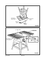
To Assemble The Extension Tables:
1.
With the 10" Table Saw upside down, align the right and left side Extension
Tables (part #5H) with the right and left ends of the Table Saw (with the beveled
edges in front). (See Figure E, and Assy. Diagram H.)
2.
Align the four mounting holes in each Extension Table (part #5H) with the four
mounting holes on each end of the 10" Table Saw. Then secure the Extension
Tables to the Table Saw, using four Hex Head Bolts (part #11H), eight Washers
(part #12H), and four Hex Nuts (#13H). (See Figure E, and Assy. Diagram H.)
3.
With assistance, stand the 10" Table saw upright.
To Attach The Front Rail:
1.
Insert five Square Head Bolts (part #10H) through the mounting holes in the front
edges of the 10" Table Saw and Extension Tables (part #5H). Allow the bolt
heads to extend out about 1/2". (See Figure F, and Assy. Diagram H.)
2.
Loosely attach a Washer (part #12H) and Hex Nut (part #13H) to each Square
Head Bolt (part #10H). (See Figure F, and Assy. Diagram H.)
SKU 46813
PAGE 11
EXTENSION
TABLE (#5H)
HEX HEAD BOLT
(#11H)
HEX HUT
(#13H)
WASHER
(#12H)
FIGURE E
10” TABLE SAW
EXTENSION
TABLE (#5H)
HEX
NUT
(#13H)
WASHER
(#12H)
EXTENSION
TABLE (#5H)
SQUARE
HEAD BOLT
(#10H)
FIGURE F
SKU 46813
PAGE 12
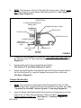
3.
NOTE: The back side of the Front Rail (part #7H) has two slots. Slide the upper
slot of the Front Rail over the Square Head Bolts (part #10H). (See Figures F,
G, and Assy. Diagram H.)
(FRONT EDGE)
10” TABLE SAW/EXTENSION
TABLES (#5H)
SQUARE HEAD BOLT (#10H)
(UPPER SLOT)
HEX NUT (#13H)
FRONT RAIL (#7H)
WASHER (#12H)
SEMI-CIRCLE
HEAD SCREW
(#2E)
SWITCH PLATE
(#3E)
(LOWER SLOT)
SQUARE
NUT(#4E)
FIGURE G
4.
To align the Front Rail (part #7H), match the 7-1/8" mark on the right scale with
the right edge of the 10" Table Saw Base (part #1G). (See Figure H, and Assy.
Diagram H.)
5.
Wrench tighten all five Square Head Bolts (part #10H).
(See Figures F, G, and Assy. Diagrams G, and H.)
6.
Secure the Right/Front End Cap (part #8H) and Left/Front End Cap (part #9H) to
the Front Rail (part #7H), using one Tapping Screw (part #1H) on each end.
(See Assy. Diagram H.)
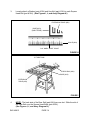
To Attach The Rear Rail:
1.
NOTE: The procedure for attaching the Rear Rail (part #3H) to the 10" Table
Saw is similar to that of attaching the Front Rail (part#7H) to the Table Saw. (See
“To Attach The Front Rail” section, Figures I, J, and Assy. Diagram H.)
2.
Insert five Square Head Bolts (part #10H) through the mounting holes in the rear
edges of the 10" Table Saw and Extension Tables (part #5H). Allow the bolt
heads to extend out about 1/2". (See Figures I, J, and Assy. Diagram H.)
SKU 46813
PAGE 13
3.
Loosely attach a Washer (part #12H) and Hex Nut (part #13H) to each Square
Head Bolt (part #10H). (See Figures I, J, and Assy. Diagram H.)
EXTENSION TABLE (#5H)
BASE (#1G)
(RIGHT EDGE)
4
5
6
7
8
9
SCALE (#6H)
7-1/8” MARK, RIGHT SCALE
FIGURE H
10” TABLE SAW
2 -1
/2 ”
REAR RAIL (#3H)
BASE (#1G)
EXTENSION
TABLE (#5H)
FIGURE I
4.
NOTE: The back side of the Rear Rail (part #3H) has one slot. Slide the slot of
the Rear Rail over the Square Head Bolts (part #10H).
(See Figures I, J, and Assy. Diagram H.)
SKU 46813
PAGE 14
10” TABLE SAW/EXTENSION TABLES (#5H)
(REAR EDGES)
REAR RAIL (#3H)
HEX NUT
(#13H)
SLOT
WASHER (#12H)
SQUARE HEAD
BOLT (#10H)
FIGURE J
5.
Wrench tighten all five Square Head Bolts (part #10H).
(See Figures I, J, and Assy. Diagram H.)
To Attach The Rip Fence And Miter Gauge:
1.
Hook the Lock Block (part #7C) under the Rear Rail (part #3H). Then, lower the
front of the Rip Fence (part #10C) into the groove on the Front Rail (part #7H).
(See Figures K, L, and Assy. Diagrams C, and H.)
2.
NOTE: The Rip Fence (part #10C) can be removed and reinstalled on the left
side of the 10" Table Saw. In this case, the Rip Fence Scale Indicator (part
#20C) can be repositioned on the left side of the Rip Fence by removing the
Semi-Circle Head Screw (part #22C) and Star Washer (part #21C). Then
reposition the Rip Fence Scale Indicator, and secure it with the Semi-Circle Head
Screw and Star Washer. (See Figures K, L, and Assy. Diagrams C, and Assy.
Diagram H.)
3.
NOTE: To attach the Miter Gauge Assembly (parts #1A through 12A), simply
slide the Miter Gauge Rod (part #10A) into the right or left slot (nearest the Saw
Blade opening, on the Saw Table (part #17H).
(See Figure B, and Assy. Diagrams A, and H.)
SKU 46813
PAGE 15
RIP FENCE (#10C)
LOCK BLOCK (#7C)
SAW TABLE
REAR RAIL (#3H)
FIGURE K
SCALE INDICATOR
(#20C)
RIP FENCE
(#10C)
FRONT RAIL
(#7H)
SAW TABLE
(#17H)
FINE ADJUSTMENT
KNOB (#30C)
RIP FENCE HANDLE
(#37C)
FIGURE L
To Attach The Power Switch:
1.
Insert two Semi-Circle Head Screws (part #2E) from the rear of the Switch Plate
(part #3E). Then, loosely screw one Square Nut (part #4E) onto each
Semi-Circle Head Screw. (See Figures B, G, and Assy. Diagram E.)
2.
While holding the Switch Plate (part #3E) to the front, insert and slide the two
Square Nuts (part #4E) into the lower slot of the Front Rail (part #7H).
(See Figures B, G, and Assy. Diagram E.)
3.
Slide the Switch Plate (part #3E) to a convenient position. Then, secure the
entire Switch Assembly (parts #1E through #12E) to the Front Rail (part #7H) by
tightening the two Semi-Circle Head Screws (part #2E).
(See Figures B, G, and Assy. Diagram E.)
SKU 46813
PAGE 16
To Assemble And Attach The Bevel And Height Handles To The Base:
1.
Insert one Screw (part #6G) each through a Bevel Handle and Height Handle
(part #5G). Tighten each Screw into a Hand Wheel Assembly (part #4G). Then,
attach an End Cap (part #7G) to each of the two Handles.
(See Figures B, M, and Assy. Diagram G.)
2.
Align one Handle Assembly (part #4G) with the Height Adjustment Rod (part
#33-I) that extends from the front of the Base (part #1G). Match the flat spots on
the Height Adjustment Rod and inside the Hand Wheel Assembly. Insert a
Socket Head Screw (part #8G) and Washer (part #9G) in the center of the Hand
Wheel Assembly and tighten. (See Figures B, M, and Assy. Diagrams G, and
I.)
3.
Align the remaining Handle Assembly (part #4G) with the Threaded Rod (part
#22-I) that extends from the right side of the Base (part #1G). Match the flat
spots on the Threaded Rod and inside the Hand Wheel Assembly. Insert a
Socket Head Screw (part #8G) and Washer (part #9G) in the center of the Hand
Wheel Assembly and tighten.
(See Figures B, M, and Assy. Diagrams G, and I.)
BEVEL LOCK (#19-I)
BEVEL HANDLE (#5G)
HEIGHT HANDLE (#5G)
FIGURE M
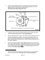
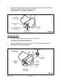
To Attach The Motor:
1.
Loosen the Bevel Lock Handle (part #19-I). Turn the Bevel Handle (part #5G)
counterclockwise until it stops. Then, retighten the Bevel Lock Handle.
(See Figure M, and Assy. Diagrams I, and G.)
2.
Align the four mounting holes in the Motor Bracket (part #7F) with the four
mounting holes in the Motor Mounting Plate (part #50-I).
(See Figure N, and Assy. Diagrams F, and I.)
SKU 46813
PAGE 17
3.
Secure the Motor Bracket (part #7F) to the Motor Mounting Plate (part #50-I),
using four Hex Head Bolts (part #9-I), eight Washers (part #52-I), four Lock
Washers (part #1-I), and four Hex Nuts (part #51-I).
(See Figure N, and Assy. Diagrams F, and I.)
HEX NUT
(#51-I)
LOCK
WASHER
(#1-I)
WASHER
(#52-I)
BELT GUARD
MOUNTING SCREW
HEX HEAD BOLT (#9-I)
MOTOR MOUNTING PLATE
(#50-I)
MOTOR (#7F)
(USE TWO SETS OF HARDWARE AT TOP, TWO SETS AT BOTTOM.)
FIGURE N
4.
Position the Spring (part #46-I) between the Motor Mounting Plate (part #50-I)
and Motor Support Base (part #45-I). (See Assy. Diagram I.)
5.
With the Spring (part #46-I) in place, insert the Motor Support Base (part #45-I) in
the Motor Mounting Plate (part #50-I). Secure the Motor Support Base to the
Motor Mounting Plate by inserting the Pivot Shaft (part #48-I) through the two
parts. Then, lock the Pivot Shaft in place, using two Retaining Rings (part #47-I).
(See Assy. Diagram I.)
6.
Insert the two Rods in the Motor Support Base (part #45-I) into the two holes in
the Trunnion Cradle (part #36-I). Push the Motor (part #7F) in as far as it will go.
Then, Thread the two Set Screws (part #42-I) downward into the Trunnion Cradle
to clamp down on the two Rods. NOTE: Do not securely tighten the two Set
Screws yet. (See Assy. Diagram I.)
To Attach The Belt Guard:
1
Open the hinged Belt Guard (parts #1F, #4F) and insert its round opening over
the Motor Pulley (part #5F). (See Figures N, O, and Assy. Diagram F.)
SKU 46813
PAGE 18
2.
Secure the Belt Guard (parts #1F, #4F) to the Motor (part #7F), using four Flat
Washers (part #3F) and four Hex Nuts (part #2F).
(See Figures N, O, and Assy. Diagram F.)
OUTER BELT
GUARD (#1F)
MOTOR PULLEY
(#5F)
FLAT WASHER (#3F)
HEX NUT (#2F)
INNER BELT
GUARD (#4F)
FIGURE O
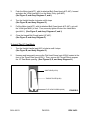
To Attach The V-Belt:
1.
Turn the Height Handle counterclockwise until it stops.
(See Figure B, and Assy. Diagram G.)
2.
Slip the V-Belt (part #40-I) onto the Pulley (41-I) inside the Base (part #1G).
(See Figure P, and Assy. Diagram I.)
PULLEY (#41-I)
OUTER BELT
GUARD (#1F)
V-BELT
(#40-I)
MOTOR
PULLEY
(#5F)
BASE
(#1G)
INNER BELT
GUARD (#4F)
FIGURE P
SKU 46813
PAGE 19
3.
Push the Motor (part #7F), with its attached Belt Guard (parts #1F, #4F), forward
and place the V-Belt (part #40-I) on the Motor Pulley (part #5F).
(See Figure P, and Assy. Diagrams F, and I.)
4.
Turn the Height Handle clockwise until it stops.
(See Figure B, and Assy. Diagram G.)
5.
Pull the Motor (part #7F), with its attached Belt Guard (parts #1F, #4F), out until
the V-Belt (part #40-I) is taut. Then, securely tighten the two Hex Head Bolts
(part #44-I). (See Figure P, and Assy. Diagrams F, and I.)
6.
Close the hinged Belt Guard (parts #1F, #4F).
(See Figure P, and Assy. Diagram F.)
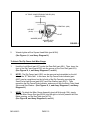
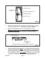
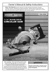
To Install The 10" Saw Blade:
1.
Turn the Height Handle (part #5G) clockwise until it stops.
(See Figure B, and Assy. Diagram G.)
2.
Unscrew and temporarily remove the Flat Head Screw (part #16H)) located at the
front of the Throat Plate (part #15H)). Then, remove the Throat Plate to expose
the 10" Saw Blade opening. (See Figures Q, R, and Assy. Diagram H.)
SAW TABLE (#17H)
THROAT PLATE (#15H)
FLAT HEAD SCREW (#16H)
SKU 46813
PAGE 20
FIGURE Q
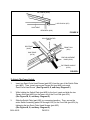
REV 04/03
SAW TABLE (#17H)
10” SAW BLADE
(#14-I)
OUTER BLADE WASHER (#15-I)
ARBOR SHAFT (#13-I)
BLADE NUT (#16-I)
FIGURE R
3.
Reach into the Saw Blade opening and remove the Blade Nut (part #16-I)) and
Outer Blade Washer (part #15-I). (See Figure R, and Assy. Diagram I.)
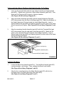
4.
Place the 10" Saw Blade (part #14-I) on the Arbor Shaft (part #13-I)).
NOTE: Make sure the teeth of the 10" Saw Blade are pointing DOWN toward
the FRONT of the Saw Table. (See Figures R, S, and Assy. Diagram I.)
10” SAW BLADE (#14-I)
SAW TABLE (#17H)
(FRONT)
(SAW TEETH POINT DOWN TOWARD FRONT OF SAW TABLE)
FIGURE S
5.
Replace the Outer Blade Washer (part #15-I) and Blade Nut (part #16-I) securely
on the Arbor Shaft (part #13-I). NOTE: In order to keep the 10" Saw Blade from
turning during this assembly procedure, place a piece of scrap wood on the Saw
Table and against the back sides of the 10" Saw Blade teeth. Then while holding
the scrap wood firmly in place, wrench tighten the Blade Nut onto the Arbor Shaft
to secure the 10" Saw Blade. (See Figures R, S, and Assy. Diagram I.)
SKU 46813
PAGE 21
6.
Once the 10" Saw Blade (part #14-I) is secured onto the Arbor Shaft (part #13-I),
replace the Throat Plate (part #15H) and tighten the Flat Head Screw (part #16H)
back in place. (See Figure Q, and Assy. Diagram H.)
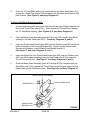
To Attach The Blade Guard Assembly:
1.
Unscrew and temporarily remove the Flat Head Screw (part #16H)) located at the
front of the Throat Plate (part #15H)). Then, remove the Throat Plate to expose
the 10" Saw Blade opening. (See Figures Q, R, and Assy. Diagram H.)
2.
Place the Blade Guard Assembly (parts #1D Through 13D) over the Saw Blade
opening on the Saw Table (part #17H). (See Assy. Diagrams D, and H.)
3.
Insert two Socket Head Screws (part #5D) and two Washers (part #4D) in the two
holes at the back of the Riving Knife (part #6D. Tighten the two Socket Head
Screws, with Washers, into the Blade Guard Bracket (part #3-I).
(See Figure T, and Assy. Diagrams D, and I.)
4.
Insert and tighten the third Socket Head Screw (part #5D) and one Washer (part
#4D) into the threaded mounting hole in the Saw Table (part #17H) under the
Throat Plate (part #15H). (See Figure T, and Assy. Diagrams D, and H.)
5.
Once the Blade Guard Assembly (parts #1D through #13D) is secured onto the
Saw Table (part #17H), replace the Throat Plate (part #15H) and tighten the Flat
Head Screw (part #16H) back in place. (See Figure Q, and Assy. Diagram H.)
SOCKET HEAD SCREW(#5D)
BLADE GUARD (#10D)
RI
VI
NG
KN
IF
E
(#
6D
)
WASHER (#4D)
BLADE GUARD
BRACKET (#3-I)
FIGURE T
SKU 46813
PAGE 22
OPERATING INSTRUCTIONS
To Raise And Lower The 10" Saw Blade:
1.
When cutting, the top edge of the Saw Blade (part #14-I) should rise about 1/4”
above the top edge of the workpiece.
2.
To raise the height of the 10" Saw Blade (part #14-I), unlock the Bevel Lock (part
#19-I). Next, turn the Height Handle (part #5G) clockwise until the desired height
is acquired. Then, re-lock the Bevel Lock.
(See Figures B, M, and Assy. Diagrams G, and I.)
3.
To lower the height of the 10" Saw Blade (part #14-I), unlock the Bevel Lock (part
#19-I). Next, turn the Height Handle (part #5G) counterclockwise until the
desired height is acquired. Then, re-lock the Bevel Lock.
(See Figures, B, M, and Assy. Diagrams G, and I.)
To Adjust The Width Of A Cut:
1.
The width of a cut is achieved by moving the Rip Fence (part #10C) to the right
or left. (See Figures B, L, and Assy. Diagram C.)
2.
The 10" Table Saw features a Scale (part #6H) on the Front Rail (part #7H) of the
unit. The Scale’s measurements are in inch increments.
(See Figures B, H, L, and Assy. Diagrams C, and H.)
3.
To position the Rip Fence (part #10C) for the desired width of a cut, unlock the
Rip Fence Handle (part #37C) by raising it upward.
(See Figures B, L, and Assy. Diagrams, C, and H.)
4.
Place the workpiece on the Saw Table (part #17H) against the Rip Fence (part
#10C). Next, slide the workpiece, and the Rip Fence, to the right or left until the
left side of the Scale (part #6H) indicates on the Scale Indicator (part #20C) the
desired width to be cut. Then, lock the Rip Fence in place by lowering the Rip
Fence Handle (part #37C). (See Figures B, L, and Assy. Diagrams C, and H.)
To Adjust The Bevel Of The 10" Saw Blade:
1.
The 10" Table Saw is capable of making bevel cuts from 90 degrees to 45
degrees.
2.
The 10" Table Saw also features a Bevel Scale (part #10G) on the front side of
the unit. (See Figure B, and Assy. Diagram G.)
SKU 46813
PAGE 23
3.
To adjust the bevel of the 10" Saw Blade (part #14-I), unlock the Bevel Lock (part
#19-I). Next, move the Bevel Handle (part #5G) to the right or left until the
desired bevel of the 10" Saw Blade is shown by the Bevel Scale (part #10G).
Then, re-lock the Bevel Lock. (See Figure B, and Assy. Diagrams G, and I.)
To Adjust The Angle Of A Cut:
1.
The 10" Table Saw is capable of making miter cuts from 0 degrees to 60
degrees.
2.
The Miter Gauge (part #4A) features a Miter Scale Indicator (part #6A) on the
front side of the unit. (See Figure B, and Assy. Diagram A.)
3.
To adjust the angle of a cut, loosen the Miter Gauge Knob (part #2A). Next,
move the Miter Gauge (part #4A) to the right or left, until the desired angle of cut
is shown by the Miter Scale Indicator (part #6A). Then, retighten the Miter Gauge
Knob. (See Figure B, and Assy. Diagram A.)
Proper Placement Of Hands During The Cutting Process:
1.
Caution: NEVER pass hands directly over or under the 10" Saw Blade (part
#14-I) when cutting the workpiece. Whenever possible, use a push stick (not
provided) to push the workpiece into the 10" Saw Blade.
(See Figure B, and Assy. Diagram.)
2.
At the start of the cut, the left hand holds the workpiece firmly on the Saw Table
(part #17H) and against the Rip Fence (part #10C). The right hand, with the aid
of a push stick, pushes the workpiece toward the turning 10" Saw Blade (part
#14-I). (See Figure B, and Assy. Diagrams C, H, and I.)
3.
After the cut is under way, the right hand with the aid of a push stick, continues
pushing the workpiece forward. Just before the cut is near completion move the
left hand safely away from the workpiece and the 10" Saw Blade (part #14-I).
Then, continue pushing the workpiece into the 10"Saw Blade, with the push stick,
until the cut is complete. (See Figure B, and Assy. Diagram I.)
INSPECTION, MAINTENANCE, AND CLEANING
1.
Caution: Always disconnect the 10" Table Saw from its electrical power supply
source before performing any inspection, maintenance, or cleaning.
SKU 46813
PAGE 24
2.
Before each use, inspect the general condition of the 10" Table Saw. Inspect the
Power Switch (part #8E), Power Plug and Cord Assembly (part #8F), and
extension cord (if used) for damage. Check for loose screws, misalignment,
binding of moving parts, broken, cracked, or improper mounting of the 10" Saw
Blade (part #14-I), broken parts and any other condition that may affect its safe
operation. If abnormal noise or vibration occurs, turn off the 10" Table Saw
immediately and have the problem corrected before further use. Do not use
damaged equipment. (See Assy. Diagrams A through I.)
3.
With a brush, soft cloth, or vacuum, remove all sawdust from the 10" Table Saw.
Do not use solvents to wipe off the 10" Table Saw, as damage may result. If
necessary, wipe with a damp cloth. You may use a mild detergent.
Do not introduce water into the electric motor through the motor vents.
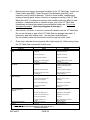
4.
Once clean, lubricate all moving parts with a light weight oil. When storing, keep
the 10" Table Saw covered with a cloth cover.
!
"#$
%&'
"'
!
!$$%&$'%
*
+
+
!
:;
:;!
+>;
?
<;
:;
=
;
:;
@
?
Q;
+
X$%Z[$\&]
+$%Z[
!
;
;
:;!
+>;
?
X$%Z[$\&]
+$%Z[
Q;
+
?
^
$
;
* + - / 0/ 12-3/-2/+40/56-7+/892-8+%+2;
+<4+*'%+0//+/+/8-+0-;2648<82/2/47<7+
=6+4008;/00+/
SKU 46813
PAGE 25
$%Z
[?
:;
@
'
^
^;
=_
_
^
z\|
;?
+>;
?
=
:;
@
!
;
:;!
;
__
?
>
;
X
?
>
`
+>;
?
X$%Z[$\&]
+$%Z[
`
$%Z[$\&]
[$z
$%Z
[
=
+
+$%
$%Z
[
z|??
++_
+
:{^
}z~
'|_
z+$%|
+;_+
_
+:
{^
[
+$%
;?
+
?
[;::<z
[
$z
[;}:$&]
?
$%Z[$\&]
::<z
`;
;?
*
?[;}
:
;
+};
$[
*&[\%&]
+*&[
$%Z[$\&]
+$%Z[
}[__
`:
PLEASE READ THE FOLLOWING CAREFULLY
THE MANUFACTURER AND/OR DISTRIBUTOR HAS PROVIDED THE PARTS LIST AND ASSEMBLY
DIAGRAMS IN THIS MANUAL AS A REFERENCE TOOL ONLY. NEITHER THE MANUFACTURER NOR
DISTRIBUTOR MAKES ANY REPRESENTATION OR WARRANTY OF ANY KIND TO THE BUYER
THAT HE OR SHE IS QUALIFIED TO MAKE ANY REPAIRS TO THE PRODUCT, OR THAT HE OR SHE
IS QUALIFIED TO REPLACE ANY PARTS OF THE PRODUCT. IN FACT, THE MANUFACTURER AND/
OR DISTRIBUTOR EXPRESSLY STATES THAT ALL REPAIRS AND PARTS REPLACEMENTS SHOULD
BE UNDERTAKEN BY CERTIFIED AND LICENSED TECHNICIANS, AND NOT BY THE BUYER. THE
BUYER ASSUMES ALL RISK AND LIABILITY ARISING OUT OF HIS OR HER REPAIRS TO THE
ORIGINAL PRODUCT OR REPLACEMENT PARTS THERETO, OR ARISING OUT OF HIS OR HER
INSTALLATION OF REPLACEMENT PARTS THERETO.
SKU 46813
PAGE 26
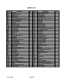
PARTS LIST
$+
'+
{+
\+
<+
+
^+
+
+
$%+
$$+
$'+
$<
'<
{<
\<
<<
<
^<
<
<
$%<
$
'
{
\
<
^
$%
$$
$'
${
$\
$<
$
$^
8
z~
=
z
&:<$%
]
z[
!
z+
&:\$
:\
};
:
=
}
[
$\
[
[
::[
'%
}[
}}[
+:+;{^
:
=
+:+;{${
}!
}
}[
+<
+=
+
:
!
>
&:$
[
[`{$'
}
SKU 46813
=$
$
$
$
$
{
$
$
$
$
$
{
{
\
{
\%
\
'\
'
'
\
'
'
'
$
$
'
$
$
$
'
$
$
\
$
\
\
$
'
$
$
$
'%
'$
''
'{
'\
'< ' '^
'
'
{%
{$
{'
{{
{\ {< { {^
{
{
$8
'8
{8
\8
<8
8
^8
8
8
$%8
$$8
$'8
${8
$
'
{
\
PAGE 27
8
]:
+
]
=<
&:<$%
>
z
z+
=
z+
z+
:@!
|~
+[
!<$
+[
+}
}
+}+
+:
+;
+}
!
|&~!
=
:$%
+;~
[z[
!
[z
!
+!
[z}
``{$'
&:<$%
!
><
=$
$
$
$
{
{
{
$
$
$
$
$
'
$
$
'
$
$
'
$
$
$
$
\
'
'
{
{
$
$
$
$
$
$
$
$
\
'
$
'
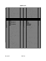
PARTS LIST
<
^
$%
$$
$'
$
'
{
\
<
^
$
'
{
\
<
^
$%
$$
$;
';
{;
\;
<;
;
^;
;
;
$%;
$$;
$';
8
!
~?
:
&:<
=<
@}
[z
:<
=<
][z
!?
!
[
::
$'
=
:=|?
[;@::
:<$'
=<
[;
X!
``{$'
}
++
|&|&]
`
+
+@
}@
>:[
'<
::[
'%
=
SKU 46813
=$
'
$
$
$
$
'
'
$
$
\
\
$
$
'
$
$
$
{
{
'
'
'
'
'
'
$
$
'
$
$
$
'
$
$
$
$
$%
'
$
${;
$\;
$<;
$;
$^;
$
;
$;
'%;
'$;
$&0
'&0
{&0
\&0
<&0
&0
^&0
&0
&0
$%&0
$$&0
$'&0
${&0
$\&0
$<&0
$&0
$^&0
$
&0
$&0
'%&0
'$&0
''&0
'{&0
'\&0
'<&0
'&0
'^&0
'
&0
'&0
{%&0
PAGE 28
8
:
<<
`!
:<$
`
$
&:<$%
><
}=<
}=
::[
$'
+;~[z[
[
=
`[
=
::[
'<
++
[[
%'%{
~?
|
$%][
[=
[
[=
[;}
=\
&:\$%
`+
[
++
=
&:<$%
=<
[
[;]
=$
'%
\
$
$
$
'
$'
$'
$'
'
$
$
$
$
'
$%
'
'
$
$
$
$
$
$
$
$
<
<
$
$
$
$
$
'
'
$
$
PARTS LIST
{$& 0
{'& 0
{{& 0
{\& 0
{<& 0
{& 0
{^& 0
{
& 0
{& 0
\%& 0
\$& 0
&&&&&&&&&
8
~
++
:|+
=
=
`
|:
=
++$<
*&[
!?
&&&&&&&&&&&&&&&&&&&&&&&&&&&&&&&&&&&
=$
$
$
$
'
$
$
$
$
$
$
$
&&&&&&
\'& 0
\{& 0
\\& 0
\<& 0
\& 0
\^& 0
\
& 0
\& 0
<%& 0
<$& 0
<'& 0
<{& 0
8
++$<
::[
'%
[
++
!;
!
:
=
=$
\
$
'
$
$
'
$
$
$
\
$
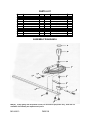
ASSEMBLY DIAGRAM A
A
A
A
A
A
A
A
A
A
A
A
A
A
NOTE: Some parts are listed and shown for illustration purposes only, and are not
available individually as replacement parts.
SKU 46813
PAGE 29
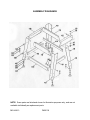
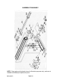
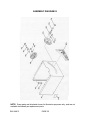
ASSEMBLY DIAGRAM B
NOTE: Some parts are listed and shown for illustration purposes only, and are not
available individually as replacement parts.
SKU 46813
PAGE 30
ASSEMBLY DIAGRAM C
NOTE: Some parts are listed and shown for illustration purposes only, and are not
available individually as replacement parts.
SKU 46813
PAGE 31
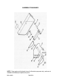
ASSEMBLY DIAGRAM D
NOTE: Some parts are listed and shown for illustration purposes only, and are not
available individually as replacement parts.
SKU 46813
PAGE 32
ASSEMBLY DIAGRAM E
NOTE: Some parts are listed and shown for illustration purposes only, and are not
available individually as replacement parts.
SKU 46813
PAGE 33
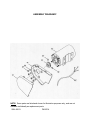
ASSEMBLY DIAGRAM F
NOTE: Some parts are listed and shown for illustration purposes only, and are not
available individually as replacement parts.
SKU 46813
PAGE 34
ASSEMBLY DIAGRAM G
NOTE: Some parts are listed and shown for illustration purposes only, and are not
available individually as replacement parts.
SKU 46813
PAGE 35
ASSEMBLY DIAGRAM H
NOTE: Some parts are listed and shown for illustration purposes only, and are not
available individually as replacement parts.
SKU 46813
PAGE 36
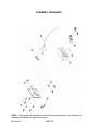
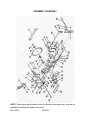
ASSEMBLY DIAGRAM I
NOTE: Some parts are listed and shown for illustration purposes only, and are not
available individually as replacement parts.
SKU 46813
PAGE 37