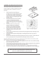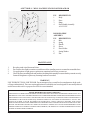
1
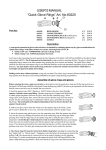
Stand for
Drill / Mill
Machine
Model 42977
Assembly & Operating
Instructions
Stand shown with Drill / Mill machine (not included)
®
3491 Mission Oaks Blvd. / Camarillo, CA 93011
www.harborfreight.com
Copyright © 2000 by Harbor Freight Tools®. All Rights Reserved.
No portion of this manual or any artwork contained herein may be reproduced in any
manner, shape or form without the express written consent of Harbor Freight Tools.
For technical questions and replacement parts, please call 1-800-444-3353.
REVISED 08/05
#42977 DRILL / MILL MACHINE STAND
SPECIFICATIONS
Construction: 6 Gauge Steel, painted
Overall Dimensions: 17.4” L x 12. 09” W x 37.8” H
(4) flanges with bolt-down holes
Net Weight: 38.58 Lbs.
1.
2.
3.
4.
5.
6.
1.
2.
3.
4.
5.
FEATURES
This sturdy steel cabinet provides a strong, vibration resistand stand for drill / mill machines.
The machine is positioned at a convenient level for standing operation.
Cabinet construction provides secure storage space for machine tools, equipment and accessories.
Pre-drilled base flanges are provided for bolt-down attachment to the floor.
Top drilled for semi-permanent attachent of drill / mill machine.
Ideally suited for mounting model # 42976 Drill / Mill Machine.
SAFETY WARNING & CAUTIONS
Never operate machinery on this stand unless the stand is firmly and permanently attached to a hard,
level, floor which is capable of supporting the weight of the stand, the machine, and any workpieces
which will be placed on it.
Never operate machinery on this stand unless the machine is firmly and permanently attached to the
stand.
This stand is primarily steel construction, and will conduct electricity. Never allow any electrical cord,
power supply, control or attachment to be attached to this stand unless it is insulated to prevent
electrical transmission.
Be sure to close and secure the cabinet door in a closed position before operating any machine attached
to or mounted on this stand.
Follow all safety warnings and precautions provided by the manufacturer or supplier of all machinery or
tools used in conjunction with this stand.
SAVE THIS MANUAL
You will need the manual for the safety warnings and cautions, assembly instructions, operating procedures,
maintenance procedures, trouble shooting, parts list, and diagram. Keep your invoice with this manual.
Write the invoice number on the inside of the front cover. Keep both this manual and your invoice in a safe,
dry place for future reference.
NOTICE
The Warnings, Cautions, and Instructions discussed in this instruction manual cannot
cover all possible conditions and situations that may occur. It must be understood by
the operator that common sense and caution are factors which cannot be built into this
product, but must be supplied by the operator.
Page 2 SKU # 42977
ASSEMBLY AND OPERATING INSTRUCTIONS
Your machine stand is fully assembled when you
receive it. However, it must be attached to the floor,
and the machine must be mounted on it prior to
operation.
1.
2.
3.
4.
5.
6.
7.
Find a location for the stand within your
workshop. Select a location which has a sturdy,
level floor which is capable of supporting the
weight of the stand, machine to be mounted on it,
and any workpieces you intend to place on the
machine or stand.
The location must also provide safe working
conditions, including adequate light and
ventilation, protection from water and weather,
G
and acess to an appropriate power supply for the
1
F
machine.
E
Locate the stand in an area that provides
A
adequate working room to manage the
D
workpieces, tools, equipment and supplies
2
3
needed to perform the intended operations.
C
B
Prepare the floor by leveling it, using cement,
Figure 1. Assembly Diagram
steel plates, wooden reinforcements or other
suitable means.
Place the stand in its intended location, and mark the floor through the bolt holes in the flanges on the
corners of the base.
Depending on the floor material, drill bolt holes or install lag bolts in the floor. Secure these as
appropriate.
Reposition the stand on the prepared floor fastening system, and secure in place. Test the stand to be
sure it is permanently and securely attached before placing the machine on the stand.
Your Drill / Mill machine may include a tray which must be positioned between the machine and the
stand. Numbers shown below refer to the diagram in Figure 1.
1.
Place the tray (#5) (not included) on the stand, aligning the four holes in the corners with the mounting
holes on the upper flange of the stand.
2.
With the help of an assistant, place the machine on the tray, with the mounting holes in the machine base
(#6) (not included) aligned with the holes in the tray and the stand.
3.
Fasten the machine securely to the stand, using four bolts (#7), washers and nuts (not included).
4.
Check to be sure the machine is securely mounted before connecting the power cord, or turning it on.
NOTE: Some parts are listed and shown for illustration purposes only
and are not available individually as replacement parts.
Page 3 SKU # 42977
#42977 DRILL / MILL MACHINE STAND PARTS DIAGRAM
G
1
F
E
A
D
2
3
C
B
P/N
1
2
3
4
DESCRIPTION
Body
Door
Hinge
Door Handle Assembly
ABCDEF
DOOR HANDLE
ASSEMBLY
P/N DESCRIPTION
A
Bolt
B
Spring
C
Handle
D
Sleeve
E
Door Holder
F
Spring Washer
G
Nut
MAINTENANCE
1.
2.
3.
4.
Keep the stand wiped down and clean.
Do not allow the stand to remain wet, and do not allow standing water to accumulate around the base.
Use applications of light grease or paint to any unpainted surfaces to prevent rust.
Check the floor mounting bolts and machine mounting bolts monthly to assure that they remain securely
fastened. Retighten or replace any fastening hardware as needed.
WARNING!
USE THE RIGHT TOOL FOR THE JOB. Do not attempt to force a small tool or attachment to do the work
of a larger industrial tool. There are certain applications for which this tool was designed. Do not modify this tool
and do not use this tool for a purpose for which it was not intended.
PLEASE READ THE FOLLOWING CAREFULLY
THE MANUFACTURER AND/OR DISTRIBUTOR HAS PROVIDED THE PARTS DIAGRAM IN THIS MANUAL AS A
REFERENCE TOOL ONLY: NEITHER THE MANUFACTURER NOR DISTRIBUTOR MAKES ANY REPRESENTATION
OR WARRANTY OF ANY KIND TO THE BUYER THAT HE OR SHE IS QUALIFIED TO MAKE ANY REPAIRS TO
THE PRODUCT OR THAT HE OR SHE IS QUALIFIED TO REPLACE ANY PARTS OF THE PRODUCT: IN FACT THE
MANUFACTURER A ND/OR DISTRIBUTOR EXPRESSLY STATES THATALL REPAIRS AND PARTS
REPLACEMENTS SHOULD BE UNDERTAKEN BY CERTIFIED AND LICENSED TECHNICIANS AND NOT BY THE
BUYER. THE BUYER ASSUMES ALL RISK AND LIABILITY ARISING OUT OF HIS OR HER REPAIRS TO THE
ORIGINAL PRODUCT OR REPLACEMENT PARTS THERETO, OR ARISING OUT OF HIS OR HER INSTALLATION
OF REPLACEMENT PARTS THERETO.
Page 4 SKU # 42977
REV 09/06