1
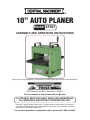
10” Auto Planer
Model 41921
Assembly And Operation Instructions
Due to continuing improvements, actual product may differ slightly from the product described herein.
®
3491 Mission Oaks Blvd., Camarillo, CA 93011
Visit our website at: http://www.harborfreight.com
To prevent serious injury, read and understand
all warnings and instructions before use.
Copyright© 1999 by Harbor Freight Tools®. All rights reserved. No portion of this manual or
any artwork contained herein may be reproduced in any shape or form without the express
written consent of Harbor Freight Tools.
For technical questions or replacement parts, please call 1-800-444-3353.
Specifications
Motor
115 V/60 Hz. 2.2 HP
Power Cord
5’9”, 3-pole, UL listed
Amps
7.1 (no load)
Overall Dimensions
22” x 16” x 23-1/4”
Cuts per Minute
16,000
Weight
89.5 lb.
Cutter Head RPM’s
8,000 (no load)
Cutting Knives
2, Bi-Metal, M-2 edge
Length of unbutted stock
8” minimum
Feed Rate
23 feet per minute
Width of stock
10” max.
Table Dimension
12-5/8”L x 10-1/4”W
Thickness of stock
1/4” - 5”
Sound Level
94 dB
Depth of cut
1/8” max.
Cutting Capacity
Included Accessories
Combination wrench
Carbon Brush set
2 hex wrenches
Blade / Knife Gauge
Features
1.
Adjustable extensions to support long workpieces.
.
Anti-kickback safety devices prevent workpieces from being ejected toward the operator.
3.
Two bi-metallic blades are adjustable and replaceable for powerful cutting performance.
4.
Compact and lightweight machine can plane workpieces up to 10” wide and 5” thick.
5.
Positive adjusting table with crank handle and easy to read thickness gauge.
6.
ON/OFF switch has removable safety lock device to prevent unauthorized use of the machine.
7.
Integral circuit breaker protects the motor from burn out.
Save this manual
You will need the manual for the safety warnings and cautions, assembly instructions, operating
procedures, maintenance procedures, trouble shooting, parts list, and diagram. Keep your invoice with this
manual. Write the invoice number on the inside of the front cover. Keep both this manual and your invoice
in a safe, dry place for future reference.
Notice
The Warnings, Cautions, and Instructions discussed in this instruction manual
cannot cover all possible conditions and situations that may occur. It must be
understood by the operator that common sense and caution are factors which
cannot be built into this product, but must be supplied by the operator.
SAFETY WARNING & CAUTIONS
READ ALL INSTRUCTIONS BEFORE USING THIS TOOL!
1.
Warning! Make sure blade is fastened and tightened down securely.
SKU 41921
For technical questions, please call 1-800-444-3353.
Page .
Keep work area clean. Cluttered areas invite injuries.
3.
Observe work area conditions. Do not use tools in damp, wet, or poorly lit locations. Don’t expose to rain. Keep work area well lit. Do not use electrically powered equipment in the presence
of flammable gases or liquids.
4.
Keep children away. Children must never be allowed in the work area. Do not let them handle
machines, tools, or equipment.
5.
Store idle equipment. When not in use, tools must be locked up in a dry location to inhibit rust.
Always lock up tools and keep out of reach of children.
6.
Do not force the tool. It will do the job better and more safely at the rate for which it was intended.
Do not use inappropriate attachments in an attempt to exceed the tool’s capacities.
7.
Use the right tool for the job. Do not use a tool for a purpose for which it was not intended.
8.
Dress properly. Do not wear loose clothing or jewelry, as they can be caught in moving parts.
Non-skid footwear is recommended. Wear restrictive hair covering to contain long hair. Always
wear appropriate work clothing.
9.
Use eye, ear, and breathing protection. Always wear ANSI approved impact safety goggles if you
are producing metal filings or wood chips. Wear an ANSI approved dust mask or respirator when
working around metal, wood, and chemical dusts and mists. Use ANSI approved ear protection
when working in a loud or noisy environment.
10.
Do not abuse the power cord. Protect the power cord from damage, either from impacts, pulling
or corrosive materials. Do not yank machine’s cord to disconnect it from the receptacle.
11.
Do not overreach. Keep proper footing and balance at all times. Do not reach over or across running machine.
1.
Maintain tools with care. Keep tools sharp and clean for better and safer performance. Follow
instructions for lubricating and changing accessories. Inspect power cord periodically and, if damaged, have it repaired by an authorized technician. Inspect all hydraulic seals for leaks prior to
use. Control handle and power switch must be kept clean, dry, and free from oil and grease at all
times.
13.
Remove adjusting keys and wrenches. Be sure that keys and adjusting wrenches are removed
from the tool or machine work surface before operation.
14.
Avoid unintentional starting. Be sure that you are prepared to begin work before turning the
start switch on.
15.
Stay alert. Watch what you are doing. Do not operate this machine when you are tired.
16.
Do not operate this machine while under the influence of alcohol, drugs, or prescription
medicines.
17.
Check for damaged parts. Before using any tool, any part that appears damaged should be carefully checked to determine that it will operate properly and perform its intended function. Check
for alignment and binding of moving parts, any broken parts or mounting fixtures, and any other
condition that may affect proper operation. Any part that is damaged should be properly repaired
or replaced by a qualified technician. Do not use the tool if any switch does not turn on and off
properly.
18.
Replacement parts and accessories. When servicing, use only identical replacement parts intended for use with this tool. Replacement parts are available from harbor freight tools. Use of any
other parts will void the warranty.
SKU 41921
For technical questions, please call 1-800-444-3353.
Page Special Warnings when using this Planing Machine
Using this Planer may create special hazards.
Take particular care to safeguard yourself and those around you.
1.
Electrical Safety. Never operate any tool if there is an electrical hazard. Never operate an
electrical tool in wet conditions. Never operate a tool with an improper electrical cord or extension
cord. Never operate an electrical tool unless it is plugged into a properly grounded outlet, which
supplies 110-120 Volts at 60 Hz. We recommend you use a circuit which is protected by an appropriate circuit breaker.
.
Ejected Material. Use safe practices to avoid injury from ejected material. Because the planer
turns at high speed, there is a danger of being injured by materials that may be ejected. Always
wear ANSI-certified eye protection. Always stand to one side of the line in which the materials are
being inserted or extruded, to avoid being hit if particles are ejected. Never allow bystanders to
be in the proximity of the Planer while in operation.
3.
Jamming. Avoid causing the planer to bog down or jam by avoiding the following situations. Do not
attempt to plane more than 1/8” at a time, or less if the wood is very hard. Do not attempt to feed
more than the stated feed rate, or less if the wood is very hard. Be sure your knife blades are kept
sharp. Check all workpieces for knots and foreign objects before planing. If the workpiece jams, it
is likely the circuit breaker will break to protect the motor.
4.
Entanglement. Use extreme caution to prevent loose materials from being caught in the
machine. Never operate this Planer with loose clothing, long hair, jewelry, or other items which
may become caught in the blades or workpieces. In case of entanglement, press the OFF switch
immediately.
5.
People with pacemakers should consult their physician(s) before use. Electromagnetic fields in
close proximity to heart pacemaker could cause pacemaker interference or pacemaker failure.
6.
Some dust created by power sanding, sawing, grinding, drilling, and other construction activities, contains chemicals known [to the State of California] to cause cancer, birth defects or
other reproductive harm. Some examples of these chemicals are: Lead from lead-based paints
Crystalline silica from bricks and cement or other masonry products Arsenic and chromium from
chemically treated lumber. Your risk from these exposures varies, depending on how often you
do this type of work. To reduce your exposure to these chemicals: work in a well ventilated area,
and work with approved safety equipment, such as those dust masks that are specially designed
to filter out microscopic particles. (California Health & Safety Code § 25249.5, et seq.)
NOTICE: No list of warnings can be all inclusive.
The operator must supply common sense, and operate this tool in a safe manner.
Unpacking
1.
Remove protective crating and materials carefully. In the event of damage in transit, contact Harbor
Freight Tools. Be sure you have all small parts accounted for before discarding packing materials.
.
Check to be sure all parts are present. In addition to the planer, you should receive the accessories
noted on page 2. You should also receive a crank handle, 2 carrying handles, and 2 table extensions, with their related hardware. If the 4 base brackets are not installed, they should be included,
together with attaching hardware.
SKU 41921
For technical questions, please call 1-800-444-3353. 07i
Page Installation
1.
It is important that the machine be located on a solid, level platform. Find a location that has easy
access to 110-120 Volt electrical service. Make sure this machine is located in a well lighted and
well ventilated area. The floor should be resistant to vibration. There must be adequate room to
insert and remove workpieces through the planer.
.
To permanently install the machine, check the platform to be sure it is even and level. Make any
required corrections to the platform. If the base brackets are not attached to each lower corner
of the machine, attach them using the supplied hardware. Mark and drill holes, and mount the
machine using bolts and nuts.
3.
If the machine will not be permanently installed, it is advisable to attach it to wooden skids by
means of the base brackets. The skids should be solid hardwood at least 1” in thickness and 2”
in width. Route these skids along each side of the machine from front to back. Each skid should
extend several inches beyond the machine to allow them to be firmly clamped to the work surface
before using the machine.
WARNING: Never operate this machine if it is not firmly attached to a work surface. If
left unattached, the machine may move along the work surface possibly falling over,
ejecting the work piece, or creating other hazards which can cause serious injury.
Electrical Power
This machine requires a 110-120V 60 Hz grounded power supply. This power is available in most
common household or workshop outlets in the United States. Please observe the following safety
precautions. (Note: Voltage variations of more than + or - 10% from the specification will result
in noticeable reduction of service, and may cause damage to the motor).
1.
Route the power cord in a way that avoids damage to the cord from other tools or machinery, and
isolates the cord from exposure to wet or corrosive conditions.
.
Avoid routing cord along the floor, walkways, or halls, where it may cause a trip hazard.
3.
Be sure the outlet is grounded and protected with an appropriate circuit breaker. Check with a
qualified electrician if you have any doubts or concerns about your electrical service.
4.
If you will use an extension cord, be sure to use a 3-prong, grounded cord. Preferably the cord will
be UL listed. Know that long extension cords cause a noticeable power drop. It is necessary to
use cords of the proper gauge to avoid excessive resistance or power drop within the cord. Please
comply with the following table.
RECOMMENDED MINIMUM WIRE GAUGE FOR EXTENSION CORDS* (120 or 240 VOLT)
NAMEPLATE AMPERES
EXTENSION CORD LENGTH
50 Feet 75 Feet 100 Feet 150 Feet
(at full load)
25 Feet
7.1 – 12.0
18
14
12
10
-
12.1 – 16.0
14
12
10
-
-
16.1 – 20.0
12
10
-
-
-
* Based on limiting the line voltage drop to five volts at 150% of the rated amperes.
SKU 41921
For technical questions, please call 1-800-444-3353.
Page Completing Assembly
WARNING: Unplug the machine before any assembly or adjustment.
Attaching the Carrying Handles
1.
Locate the two carrying handles (349), and their hardware, Screws (327).
.
Attach the handles to the top of the machine firmly using the screws.
Installing the table extensions
1.
With the roller up, place each table extension bracket (157) onto the table (125) and attach using
two cap screws (164). Be sure the bracket assemblies are firmly attached, but are able to rotate
up for storage.
.
Adjust each table extension so that a workpiece supported by the roller is level and in the same
plane with the table. Do this by adjusting the cap
screws (1) in or out as required. See Figure 2. Check
the adjustment by placing a straight edge at least
24” long through the machine, and resting on the
table and both extension rollers. When the extension
is properly adjusted, lock the cap screws in place
with the lock nuts (2).
Figure 2. Table Extension Adjustment
Setting the Cutting Depth
1.
Place the Table Adjustment Handle (150) over the square-ended Control Screw (130) which protrudes through the top of the machine.
.
Turn the Table Adjustment Handle to raise or lower the Table to the desired cutting thickness.
3.
Read the cutting depth on the scale on the right of the machine.
4.
Remove the Table Adjustment Handle before operating.
Operating the Power Switch
1.
The power switch is on the lower right front of the machine.
.
The Safety Switch Cover must be in place to operate the Power
Switch. You can remove the Cover and store it in a safe place
to prevent unauthorized use.
3.
Press the Switch UP to turn
the machine ON, and DOWN
to turn it OFF.
Integral Circuit Breaker
1.
The circuit breaker trips if the
amp draw exceeds 10 A., preventing motor burn out if the
planer jams, or if there is a
power surge.
.
To reset, correct the error
condition and press the button
back in.
SKU 41921
Fig. 4 Power Switch and
Integral Circuit Breaker
Fig. 3 Crank and
Cutting Depth Scale
For technical questions, please call 1-800-444-3353.
Page Safety Check Prior to Operation
Warning: Unplug the machine and turn the power switch OFF before inspecting the machine.
1.
Check to be sure all parts and fasteners are properly attached and tight.
.
Be sure the blade is properly installed and adjusted.
3.
Check the operation of the Table Adjustment Handle (150). One rotation of the handle will raise
or lower the table by 2mm (0.0787”).
Plug in the machine to prepare to check the motor and blade function.
1.
Turn ON the machine by moving the switch up. Note: The safety switch cover must be in place for
the switch to operate.
.
Do not insert any work materials into the planer. Allow it to spin up to full speed. Determine if the
machine is operating smoothly, not making any excessive noises or vibrations. If not, the machine
is ready to operate.
Warning: check blade setting and tightness before initial use.
Operation
WARNING: Wear ANSI-approved eye protection, and observe all safety precautions when operating.
1.
Measure your workpiece to determine its current thickness, and the amount you desire to plane
off. Maximum depth of cut is 1/8”; if you need to remove more than this, make repeated cuts.
.
Set the cutting depth by turning the Table Adjustment Handle (150) until the pointer indicates the
correct depth on the scale.
3.
Turn the machine OFF and unplug the power cord. Insert the workpiece into the planer and visually
check your setting to assure that no more than 1/8” will be planed off the workpiece.
Warning: Attempting to plane more than 1/8” at a time may cause the planer to jam; potentially
causing the workpiece to splinter and be ejected from the machine, or the motor to jam and
possibly burn out. Never plane more than 1/8” at a time.
4.
When you are satisfied the cut is properly set up, remove the workpiece from the machine. Plug in
the planer, and turn the power switch ON. Allow the planer to spin up to full speed.
5.
Position the workpiece on the extension roller and table so that it is level. If you are planing a long
board, you may need support tables on both sides
of the planer to keep the workpiece level as its full
length passes through the planer.
6.
Feed the workpiece into the planer, no faster than
the stated feed rate (23 feet per minute). The planer
should maintain its speed. If the planer slows down
noticeably, reduce the feed rate. If the planer still
bogs down, remove the workpiece and adjust for
a shallower cut.
7.
Use a wooden pusher tool to push the board through
the planer. You can also grip the finished portion of
the workpiece, and pull it out of the planer.
WARNING: Keep hands farther away from intake than
rollers on extensions.
SKU 41921
Fig 5. DO NOT Place Your Hand
Inside the Extension Rollers
For technical questions, please call 1-800-444-3353.
Page Suggestions for Better Planing
This tool is ideal for finishing wood boards. You can use it to level or remove veneers. You can level warped
boards. You can convert rough boards into finished wood. You can shape boards to a desired size.
Select your wood with care.
1.
Be sure your wood is dry and properly cured. Green or wet wood will continue to shrink and may
warp after planing.
.
Do not use splintered wood, or wood which may splinter while being worked. Some species such
as Eucalyptus or Bamboo are prone to splintering and are not suitable for planing.
3.
Do not use any boards with loose knots, or knots which are significantly harder than the surrounding wood. These can break out or come loose during planing, which can jam the machine.
4.
Check your workpiece for foreign objects, such as nails, screws or stones which may be embedded in the wood. Remove any foreign objects before planing, or select another workpiece. Foreign
objects may come loose and be ejected from the machine causing a hazard. Foreign objects may
also damage the knife blades.
Plan the best way to handle warped and bowed boards.
1.
Boards which are warped across the width of the board
(“cupped” boards) should have the top planed flat first,
then turned over and the bottom planed flat.
.
Depending on the width of the board, you can reduce
waste in planing cupped boards by ripping them lengthwise first, then planing both resulting pieces.
3.
Boards which are warped lengthwise (“bowed” boards)
are difficult to successfully straighten out. The feed rollers in the planer will effectively straighten out bowed
boards as they pass through. But the board will remain
bowed when freestanding. If the bowed board cannot
be used as is, it is best to select another board.
Figure 6. A Cupped Board
Figure 7. A Bowed Board
It is important to consider wood grain when planing.
1.
.
It is best to cut in such a way that the planer’s knife
blades are cutting with the grain. This will reduce chipping, and result in a smoother finished surface. You
can identify the grain direction by looking at the edge
or end of the board. You can also often feel the grain
with your fingers.
In some boards, the grain direction reverses part
way along the board. If possible, cut such boards
at the transition point, and plane each piece separately.
Avoiding Kickback.
Figure 8. Feed the Board so the
Knife Blades cut WITH the Grain
Figure 9. Boards Whose Grain
Changes Direction in the Middle.
1.
Always insert boards for planing into the front of the
machine. The insertion direction is indicated by the arrow on top of the left belt cover.
.
Anti-kickback devices are installed along the top edge of the front opening of the planer.
WARNING: Avoid kickback by never overloading the machine.
SKU 41921
For technical questions, please call 1-800-444-3353.
Page Maintenance
When not in use, keep the machine unplugged and covered. Store it in a dry place. Store the
safety switch cover in a safe place to prevent unauthorized use. Unplug the machine before
doing any maintenance.
1.
Regular lubrication is required to keep your planer in good condition, and assure a long
service life.
Note: Do not apply grease to the belts.
a. Keep the table guide rods clean, and coated with a light coat of grease.
b. Occasionally remove the top and apply a light grease to the bearings at each end of the cutter
head. The motor bearings are sealed and do not require additional lubrication.
c. Remove the panels on both sides of the planer, and apply a light grease to the chains.
d. Apply a light coat of grease to the chain on the underside of the machine.
.
Keep the motor and electrical controls dry and clean. Keep the motor free of chips, sawdust,
grease, and debris.
Adjusting the Cutting Knives
WARNING: Be sure the machine is turned OFF and
UNPLUGGED before attempting any adjustments.
The Cutter Head assembly can be accessed by
removing the cover from the top of the machine.
1.
Remove the top cover (326) from the machine by
removing the bolts securing it.
.
Please refer to Figure 11 when checking knife adjustment. Position the knife Gauge (E) on the cutter
head and knife blade as shown. The gauge must
Figure 10. Checking the Knife Blade
contact the knife blade and the cutter head at all
three points shown. The blade is adjusted too low if there is a
visible space between the blade edge and the gauge. The knife
blade is too high when the gauge rocks from side to side on the
cutter head when contacting the knife blade.
3.
To adjust the blade setting, loosen the locking nuts (A) just
enough to allow the blade (C) to move against the Lock Bar
(B). To raise the knife blade, turn adjustment screw (D) counterclockwise. To lower the knife blade, turn the adjustment screw
clockwise and press down on the blade.
Note: It is important that you adjust the blade along its entire length,
so the blade has a consistent depth.
4.
When the knife blade is properly adjusted, tighten the locking
nuts (A) firmly to lock it in place. Be sure these nuts are on tight. Figure 11. Knife Blade Gauge
Re-check alignment to be sure the knife blade did not slip during tightening.
SKU 41921
For technical questions, please call 1-800-444-3353.
Page Troubleshooting
Unplug the machine before attempting any repairs.
If the Planer runs roughly or has excessive vibration:
1.
Verify that Knife Blades are not chipped, are securely installed, and are adjusted properly.
.
Verify that all chains and belts are properly routed on their pulleys and sprockets, and are not
loose.
3.
Verify that the Table is not damaged, and operates smoothly.
4.
Be sure the Crank is removed from the Planer before operation.
If the Planer will not operate at all:
1.
Verify that the planer is plugged in, the main circuit breaker in the power source is operational, and
the integral circuit breaker on the machine is operational. If either circuit breaker is open, investigate
further to determine and repair the cause of the fault.
.
Verify that the Planer is not jammed.
3.
Inspect the carbon brushes in the motor to determine if they are in good condition.
4.
Look for broken, damaged, or loose electrical connections. Repair before continuing.
If the Motor runs roughly or slowly:
1.
Check for debris in the cutting assembly or in the chains or belts.
.
Inspect the carbon brushes, replace if necessary.
3.
Verify that the power source supplies the correct Voltage and Amperage.
If the Planer cuts unevenly, poorly, or produces a rough or chipped finish:
1.
Inspect the Knife Blades to be sure they are properly installed and adjusted.
.
Remove the Knife Blades and have them sharpened by a sharpening service.
3.
Review the suggestions for selecting a workpiece, and adjusting the depth of cut.
4.
Cut only with the wood grain.
Changing the Carbon Brushes:
1.
Check carbon brushes every 10-15 hours of operation.
.
Brushes are accessed by turning the machine on its
side. Motor is on machine’s underside. The brush
holders are on the sides of the motor. Remove brush
holders by turning them with a coin.
3.
Each brush has a line marked on its side. When the
brush has worn to the line, or if it is cracked or chipped,
replace both carbon brushes.
Figure 12. Checking and
Replacing the Carbon Brushes
SKU 41921
For technical questions, please call 1-800-444-3353.
Page 10
#41921 10” Auto Planer Parts List, Main Unit
Please refer to Parts Diagram on Page 12
Part
101
102
103
104
105
106
107
108
109
110
111
112
113
114
115
116
117
118
119
120
121
122
123
124
125
126
127
128
129
130
131
132
Description
Washer, m6
Cap Screw, m6 x 12
Screw, m6 x 50
Washer, m6
Retaining Ring, m15
Shaft
Sprocket
Retaining Ring, m15
Shaft
Pawl
Bushing
Washer, m6
Sprocket Cover
Cap Screw, m6 x 16
Screw Bolt
Frame
Sprocket, m16
Sprocket Frame
Sprocket
Washer, m10
Nut, m10
Washer, m8
Nut, m8
Sprocket Frame
Table
Side Guide
Screw, m5 x 10
Backing Board
Chain
Control Screw, m16
Pointer
Screw, m6 x 10
Q’ty
Part
2
2
1
1
1
1
1
1
1
15
31
4
1
4
1
2
3
4
4
4
4
2
2
4
1
4
8
1
1
1
1
1
133
134
135
136
137
138
139
140
141
142
143
144
145
146
147
148
149
150
151
152
153
154
155
156
157
158
159
160
161
162
163
164
Description
Wood Screw
Base Bracket
Cap Screw, m6 x 16
Nut, m6
Scale
Washer, m6
Screw, m6 x 16
Washer, m8
Right Cover
Bolt Screw, m8 x 50
Screw, m8 x 16
Switch Cover
Switch
Power Cord
Belt Cover
Washer, m6
Nut, m6
Table Adjustment Handle
Left Cover
Cap Screw, m8 x 20
Cap Screw, m8 x 16
Motor Cord
Circuit Breaker, 230V/10A
Strain Relief Bushing
Table Extension Bracket
Roller
Block
Cap Screw, m6 x 16
Pin, m8 x 20
Cap Screw, m6 x 20
Nut, m6
Screw, m8 x 16
Q’ty
4
4
8
8
1
8
8
8
1
2
8
1
1
1
1
2
2
1
1
8
4
1
1
1
2
2
4
4
4
4
4
4
PLEASE READ THE FOLLOWING CAREFULLY
THE MANUFACTURER AND/OR DISTRIBUTOR HAS PROVIDED THE PARTS DIAGRAM IN THIS MANUAL
AS A REFERENCE TOOL ONLY: NETHER THE MANUFACTURER NOR DISTRIBUTOR MAKES ANY
REPRESENTATION OR WARRANTY OF ANY KIND TO THE BUYER THAT HE OR SHE IS QUALIFIED TO
MAKE ANY REPAIRS TO THE PRODUCT OR THAT HE OR SHE IS QUALIFIED TO REPLACE ANY PARTS
OF THE PRODUCT: IN FACT THE MANUFACTURER A ND/OR DISTRIBUTOR EXPRESSLY STATES THAT
ALL REPAIRS AND PARTS REPLACEMENTS SHOULD BE UNDERTAKEN BY CERTIFIED AND LICENSED
TECHNICIANS AND NOT BY THE BUYER. THE BUYER ASSUMES ALL RISK AND LIABILITY ARISING
OUT OF HIS OR HER REPAIRS TO THE ORIGINAL PRODUCT OR REPLACEMENT PARTS THERETO, OR
ARISING OUT OF HIS OR HER INSTALLATION OF REPLACEMENT PARTS THERETO.
SKU 41921
For technical questions, please call 1-800-444-3353.
Page 11
#41921 10” Auto Planer Parts Diagram, Main Unit
Please refer to Parts List on Page 11
SKU 41921
For technical questions, please call 1-800-444-3353.
Page 12
#41921 10” Auto Planer, Additional Parts List
Please refer to Parts Diagrams on Page 14 and 15
Part
Description
Motor Assembly
Q’ty
Part
Description
Q’ty
317
Cutter Head
1
201
Motor Housing
1
318
Key, m5 x 5 x 20
1
202
Stator
1
319
Driven Pulley
1
203
Washer, m5
1
320
Knife Gauge
1
204
Fan Casing
1
321
Adjustable Bolt
4
205
Screw, m5 x 85
2
322
Non-Belt, J-750-6
1
206
Bearing, 6201ZZ
1
323
Nut, m16 x 1.5
2
207
Silicone Steel Sheet
1
324
Knife Lock Plate
2
208
Bearing, 6029ZZ
1
325
Blade Knife
2
209
Motor Pulley
1
326
Top Cover
1
210
Brush Holder
2
327
Screw, m8 x 20
4
211
Carbon Brush
2
328
Gear Box
1
212
Brush Cap
2
329
Gear
1
213
Motor Box
1
330
Shaft
1
214
Cap Screw, m5 x 12
4
331
Steel Ball, m4
1
215
Washer, m5
4
332
Steel Ball, m5
1
216
Pad Head Screw, m5 x 50
2
333
Pinion
1
217
Pad Head Screw, m5 25
2
334
Gear
1
335
Knife Lock Bolt
12
Cutter Assembly
301
Frame Support
2
336
Collar
2
302
Screw
2
337
Pinion
1
303
Girder Stay
2
338
Steel Ball, m4
1
304
Screw
1
339
Gear
1
305
Splash Apron
1
340
Bearing, 6029ZZ
1
306
Spring
4
341
Bearing, 60202ZZ
1
307
Roller Chain
1
342
Pinion Gear
1
308
Retaining Ring
6
343
Free Pully
1
309
Sprocket
4
344
Non-Belt, J-246-4
1
310
Bushing
4
345
Face Screw
6
311
Free Roller
2
346
Axle
1
312
Tension Spring
1
347
Collar
31
313
Chain
1
348
Pawl
30
314
Cap Screw, m6 x 22
8
349
Handle
2
315
Free Roller Bracket
2
350
Cover
1
316
Bearing, 60203ZZ
2
SKU 41921
For technical questions, please call 1-800-444-3353.
Page 13
#41921 10” Auto Planer Parts Diagram, Motor Assembly
Please refer to Parts List on Page 13
SKU 41921
For technical questions, please call 1-800-444-3353.
Page 14
#41921 10” Auto Planer Parts Diagram, Cutter Assembly
Please refer to Parts List on Page 13
SKU 41921
For technical questions, please call 1-800-444-3353.
Page 15