1
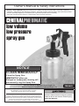
Owner’s Manual & Safety Instructions
Save This Manual Keep this manual for the safety warnings and precautions, assembly, operating,
inspection, maintenance and cleaning procedures. Write the product’s serial number in the back of the manual
near the assembly diagram (or month and year of purchase if product has no number).
Keep this manual and the receipt in a safe and dry place for future reference.
low volume
low pressure
spray gun
NOTICE
CLEAN IMMEDIATELY
Clean the Spray Gun
IMMEDIATELY after use.
Delayed or inadequate cleaning will
permanently clog the Spray Gun.
Visit our website at: http://www.harborfreight.com
Email our technical support at: [email protected]
ITEM 60612
When unpacking, make sure that the product is intact
and undamaged. If any parts are missing or broken,
please call 1-800-444-3353 as soon as possible.
Copyright© 2012 by Harbor Freight Tools®. All rights reserved.
No portion of this manual or any artwork contained herein may be reproduced in
any shape or form without the express written consent of Harbor Freight Tools.
Diagrams within this manual may not be drawn proportionally. Due to continuing
improvements, actual product may differ slightly from the product
described herein. Tools required for assembly and service may not be included.
Read this material before using this product.
Failure to do so can result in serious injury.
SAVE THIS MANUAL.
NOTICE
Clean the Spray Gun IMMEDIATELY after use.
Delayed or inadequate cleaning will permanently clog the Spray Gun.
Safety
Table of Contents
Safetye�������������������������������������������������2
Specifications......................................5
Setup...................................................6
Operationa�������������������������������������������10
Maintenancei��������������������������������������14
Parts List and Diagram.......................18
Warranty.............................................20
Setup
WARNING SYMBOLS AND DEFINITIONS
This is the safety alert symbol. It is used to alert you to
potential personal injury hazards. Obey all safety messages
that follow this symbol to avoid possible injury or death.
Indicates a hazardous situation which, if not avoided,
will result in death or serious injury.
Indicates a hazardous situation which, if not avoided,
could result in death or serious injury.
Indicates a hazardous situation which, if not avoided,
could result in minor or moderate injury.
Operation
Addresses practices not related to personal injury.
IMPORTANT SAFETY INSTRUCTIONS
INSTRUCTIONS PERTAINING TO A RISK OF FIRE,
ELECTRIC SHOCK, OR INJURY TO PERSONS
Maintenance
The warnings and precautions discussed in this manual cannot cover all possible conditions and
situations that may occur. It must be understood by the operator that common sense and caution
are factors which cannot be built into this product, but must be supplied by the operator.
WARNING – When using tools, basic precautions should always be followed, including the following:
Work Area
a. Keep the work area clean and well lighted.
Cluttered benches and dark areas
increase the risks of electric shock,
fire, and injury to persons.
Page 2
b. Keep bystanders, children, and
visitors away while operating the tool.
Distractions are able to result in
the loss of control of the tool.
For technical questions, please call 1-800-444-3353.
Item 60612
NOTICE
Personal Safety
c. Do not overreach. Keep proper
footing and balance at all times.
Proper footing and balance enables better
control of the tool in unexpected situations.
d.
b. Dress properly. Do not wear loose clothing
or jewelry. Contain long hair.
Keep hair, clothing, and gloves away
from moving parts. Loose clothes, jewelry, or
long hair increases the risk of injury to persons e.
as a result of being caught in moving parts.
Use safety equipment.
Wear heavy‑duty work gloves and
a NIOSH‑approved respirator
during use. Non‑skid safety shoes
and a hard hat must be used for the
applicable conditions.
Always wear eye protection.
Wear ANSI‑approved
safety goggles.
Setup
a. Stay alert. Watch what you are
doing and use common sense when
operating the tool. Do not use the
tool while tired or under the influence
of drugs, alcohol, or medication.
A moment of inattention while operating the
tool increases the risk of injury to persons.
Safety
Clean the Spray Gun IMMEDIATELY after use.
Delayed or inadequate cleaning will permanently clog the Spray Gun.
a. Do not force the tool. Use the correct
tool for the application. The correct tool
will do the job better and safer at the
rate for which the tool is designed.
c. Store the tool when it is idle out of reach
of children and other untrained persons.
A tool is dangerous in the hands
of untrained users.
b. Disconnect the tool from the air source
before making any adjustments,
changing accessories, or storing the tool.
Such preventive safety measures reduce
the risk of starting the tool unintentionally.
Turn off and detach the air supply, safely
discharge any residual air pressure, and
release the throttle and/or turn the switch to
its off position before leaving the work area.
d. Check for misalignment or binding of
moving parts, breakage of parts, and any
other condition that affects the tool’s
operation. If damaged, have the tool serviced
before using. Many accidents are caused
by poorly maintained tools. There is a risk
of bursting if the tool is damaged.
c. Use only lubricants supplied with the
tool or specified by the manufacturer.
b. When servicing a tool, use only
identical replacement parts.
Use only authorized parts.
Item 60612
For technical questions, please call 1-800-444-3353.
Page 3
Maintenance
e. Use only accessories that are identified
by the manufacturer for the specific
tool model. Use of an accessory not
intended for use with the specific tool model,
increases the risk of injury to persons.
Service
a. Tool service must be performed only
by qualified repair personnel.
Operation
Tool Use and Care
NOTICE
Clean the Spray Gun IMMEDIATELY after use.
Delayed or inadequate cleaning will permanently clog the Spray Gun.
Safety
Air Source
a.
Setup
Never connect to an air source
b. Never use oxygen, carbon dioxide,
that is capable of exceeding
combustible gases or any bottled
200 psi. Over pressurizing the tool
gas as an air source for the tool.
may cause bursting, abnormal
Such gases are capable of explosion
operation, breakage of the tool or
and serious injury to persons.
serious injury to persons. Use only clean, dry,
regulated compressed air at the rated pressure
or within the rated pressure range as marked
on the tool. Always verify prior to using the
tool that the air source has been adjusted to
the rated air pressure or within the rated
air-pressure range.
SAVE THESE INSTRUCTIONS.
Symbol Definitions
Symbol
Operation
PSI
Property or Statement
Pounds per square inch of pressure
CFM
Cubic Feet per Minute flow
SCFM
Cubic Feet per Minute flow
at standard conditions
NPT
National pipe thread, tapered
NPS
National pipe thread, straight
Symbol
Property or Statement
WARNING marking
concerning Risk of Eye Injury.
Wear ANSI‑approved eye protection.
WARNING marking concerning
Risk of Respiratory Injury.
Wear NIOSH‑approved respirator.
WARNING marking concerning
Risk of Explosion.
Maintenance
Page 4
For technical questions, please call 1-800-444-3353.
Item 60612
NOTICE
Clean the Spray Gun IMMEDIATELY after use.
Delayed or inadequate cleaning will permanently clog the Spray Gun.
4. Read all of the information concerning
coating products and cleaning solvents.
Do not use chlorinated solvents
(e.g. 1‑1‑1 trichloroethylene and
dichloromethane, also known as
methylene chloride) to clean spray guns.
Many spray guns contain aluminum,
which reacts strongly to chlorinated
solvents. Contact the solvent or coating
manufacturer as needed regarding
potential chemical reactions.
5. Industrial applications must
follow OSHA requirements.
6. Spraying hazardous materials may
result in serious injury or death.
Do not spray pesticide, acid, corrosive
material, fertilizer, or toxic chemicals.
7. Paints and solvents may be harmful or fatal if
swallowed or inhaled. Avoid prolonged skin
contact with solvents or paints as they will
irritate skin. After any contact, immediately
wash off exposed area with hot, soapy water.
9. Install an in-line shutoff valve
to allow immediate control over
the air supply in an emergency,
even if a hose is ruptured.
10. Air hose fittings may get hot during use.
Allow fittings to cool before disconnecting.
11. WARNING: Some dust created by power
sanding, sawing, grinding, drilling, and
other construction activities, contains
chemicals known [to the State of California]
to cause cancer, birth defects or other
reproductive harm.
Some examples of these chemicals are:
• Lead from lead-based paints
• Crystalline silica from bricks and cement or
other masonry products
• Arsenic and chromium from
chemically treated lumber
Your risk from these exposures varies,
depending on how often you do this type
of work. To reduce your exposure to these
chemicals: work in a well ventilated area, and
work with approved safety equipment, such as
those dust masks that are specially designed
to filter out microscopic particles.
(California Health & Safety Code
§ 25249.5, et seq.)
WARNING: The brass components of
this product contain lead, a chemical
known to the State of California to cause
birth defects (or other reproductive harm).
(California Health & Safety Code
§ 25249.5, et seq.)
Specifications
Maximum Air Pressure
Air Inlet
Cup Capacity
Item 60612
50 PSI
1/4 IN. - 18 NPS
33 oz.
Air Consumption
For technical questions, please call 1-800-444-3353.
5.5 CFM @ 20 PSI
9 CFM @ 45 PSI
Page 5
Setup
3. Do not spray near open flames, pilot lights,
stoves, heaters, the air compressor, or
any other heat source. Most solvents and
coatings are highly flammable, particularly
when sprayed. Maintain a distance of at least
25 feet from the air compressor. If possible,
locate the air compressor in a separate room.
Operation
2. Do not exceed maximum air pressure.
8. Attach all accessories properly to the
tool before connecting the air supply.
A loose accessory may detach
or break during operation.
Maintenance
1. Do not direct spray at people or animals.
Safety
Specific Safety Instructions
NOTICE
Clean the Spray Gun IMMEDIATELY after use.
Delayed or inadequate cleaning will permanently clog the Spray Gun.
Safety
Components and Controls
Lock Ring
Pattern
Adjustment
Knob
Nozzle
Setup
Fluid
Knob
Air
Knob
Trigger
Gun
Body
Operation
Air Inlet
Maintenance
Paint Cup
Figure A
Page 6
For technical questions, please call 1-800-444-3353.
Item 60612
NOTICE
Initial Set Up
Read the ENTIRE IMPORTANT SAFETY INFORMATION section at the beginning of this
manual including all text under subheadings therein before set up or use of
this product.
Safety
Clean the Spray Gun IMMEDIATELY after use.
Delayed or inadequate cleaning will permanently clog the Spray Gun.
Note: For additional information regarding the parts listed in the following
pages, refer to the Assembly Diagram near the end of this manual.
1. This air tool may be shipped with a
protective plug covering the air inlet.
Remove this plug before set up.
2. Before first use, clean the Spray Gun using
a solvent‑based thinner. If not removed,
the material used for testing and corrosion
prevention will contaminate paint.
Setup
Before Setup
Air Supply Setup
Note: Do not use an automatic oiler system or
add oil to airline. The oil will contaminate the
material being propelled, ruining the final result.
2. Attach an air hose to the
compressor’s air outlet. Connect the
air hose to the air inlet of the tool.
Other components, such as a coupler plug
and quick coupler, will make operation
more efficient, but are not required.
Item 60612
WARNING! TO PREVENT SERIOUS INJURY
FROM ACCIDENTAL OPERATION:
Do not install a female quick coupler
on the tool. Such a coupler contains
an air valve that will allow the air tool to
retain pressure and operate accidentally
after the air supply is disconnected.
Note: Air flow, and therefore tool
performance, can be hindered by
undersized air supply components.
3. The air hose must be long enough to reach
the work area with enough extra length
to allow free movement while working.
4. Close the in-line shutoff valve between
the compressor and the tool.
5. Turn on the air compressor according to
the manufacturer’s directions and allow it
to build up pressure until it cycles off.
For technical questions, please call 1-800-444-3353.
Page 7
Maintenance
1. Incorporate a filter, regulator with pressure
gauge, in-line shutoff valve, and quick coupler
for best service, as shown on Figure B on
page 8 and Figure C on page 9.
An in-line shutoff ball valve is an important
safety device because it controls the air
supply even if the air hose is ruptured.
The shutoff valve should be a ball valve
because it can be closed quickly.
Operation
TO PREVENT SERIOUS INJURY FROM EXPLOSION:
Use only clean, dry, regulated, compressed air to power this tool. Do not use
oxygen, carbon dioxide, combustible gases, or any other bottled gas as a power
source for this tool.
NOTICE
Clean the Spray Gun IMMEDIATELY after use.
Delayed or inadequate cleaning will permanently clog the Spray Gun.
8. If the tool will not be used at this time,
turn off and detach the air supply and
safely discharge any residual air pressure
to prevent accidental operation.
A
Description
Maintenance
A
B
C
D
Operation
Figure B: Portable Air Supply Setup
E
F
Setup
Function
7. Inspect the air connections for leaks.
Repair any leaks found.
Connects air to tool
Prevents dirt and condensation from damaging tool or workpiece
Adjusts air pressure to tool
Provides quick connection and release
Prevents water vapor from damaging workpiece
For fine tuning airflow at tool
Note: Residual air pressure should not be
present after the tool is disconnected from
the air supply. However, it is a good safety
measure to attempt to discharge the tool in a
safe fashion after disconnecting to ensure that
the tool is disconnected and unpowered.
A Air Hose
B Filter
D Regulator
E Coupler and Plug
C Air Cleaner / Dryer*
F Air Adjusting Valve*
*Optional components.
Safety
6. Adjust the air compressor’s output
regulator so that the air output is enough
to properly power the tool, but the output
will not exceed the tool’s maximum air
pressure at any time. Adjust the pressure
gradually, while checking the air output
gauge to set the right pressure range.
Page 8
For technical questions, please call 1-800-444-3353.
Item 60612
Item 60612
For technical questions, please call 1-800-444-3353.
D
E
F
G
H
C
F
E
Function
F
Page 9
Maintenance
I
I
J
Operation
Filter
Description
J
H
L
Coupler and Plug
J Regulator
K Lubricator*
I
N
K
H
L
O
Function
M
F
Safety
Prevents dirt and condensation
contamination
Adjusts air pressure to tool
For air tool lubrication
Provides quick connection
and release
Increases coupler life
Prevents moisture contamination
For fine tuning airflow at tool
L
Setup
M Leader Hose*
N Air Cleaner / Dryer*
O Air Adjusting Valve*
*Optional components.
Non-lubricated
Tools
C
C
For noise and vibration reduction
Secures air compressor in place
Isolates sections of system
Ball Valve
for maintenance
Isolation Hose
For vibration reduction
Main Air Line - 3/4″ min. Distributes air to branch lines
Ball Valve
To drain moisture from system
Branch Air Line -1/2″ min. Brings air to point of use
Air Hose
Connects air to tool
Description
B
A
A Vibration Pads
B Anchor Bolts
B
A
C D
G
Lubricated
Tools
Slope
Figure C: Stationary Air Supply Setup
Clean the Spray Gun IMMEDIATELY after use.
Delayed or inadequate cleaning will permanently clog the Spray Gun.
NOTICE
NOTICE
Clean the Spray Gun IMMEDIATELY after use.
Delayed or inadequate cleaning will permanently clog the Spray Gun.
Safety
Operating Instructions
Read the ENTIRE IMPORTANT SAFETY INFORMATION section at the beginning of this
manual including all text under subheadings therein before set up or use of this
product.
Inspect tool before use, looking for damaged, loose, and missing parts.
If any problems are found, do not use tool until repaired.
Workpiece and Work Area Set Up
Setup
1. Designate a work area that is clean
and well‑lit. The work area must not
allow access by children or pets to
prevent distraction and injury.
2. Route the air hose along a safe
path to reach the work area without
creating a tripping hazard or exposing
the air hose to possible damage.
The air hose must be long enough to reach
the work area with enough extra length
to allow free movement while working.
3. Before spraying, mask nearby
objects not being sprayed and lay
cloths (not included) on the floors.
4. Prepare the workpiece according to
paint manufacturer’s directions.
Operation
Maintenance
Page 10
For technical questions, please call 1-800-444-3353.
Item 60612
NOTICE
Clean the Spray Gun IMMEDIATELY after use.
Delayed or inadequate cleaning will permanently clog the Spray Gun.
Safety
Spray Gun Setup Adjustment
TO PREVENT SERIOUS INJURY:
Do not adjust or tamper with any control or component in a way not specifically explained
within this manual. Improper adjustment can result in tool failure or other serious hazards.
CAUTION! Keep hands away from Trigger while making adjustments.
Note: This Spray Gun is meant
for spraying latex, stains and varnish.
Fan Direction
Lock Ring
Horizontal Fan
Setup
Paint Preparation and Filling
Note: Proper paint mixture is essential.
Follow the manufacturer’s directions. Most paints
will spray easily if they are thinned properly.
1. Thin the paint according to manufacturer’s
directions and mix thoroughly.
Nozzle
Vertical
Fan
2. Carefully strain the paint through
a paint strainer or a piece of cheesecloth.
Figure D: Fan Direction
4. Start the air compressor and set
the regulator to needed pressure.
Do not exceed maximum air pressure.
1. To change the direction of the
fan from horizontal to vertical,
loosen the Lock Ring and turn the Nozzle 90°.
5. Test the consistency by spraying
on a piece of scrap material.
2. After the adjustment, tighten
the Lock Ring by hand.
Item 60612
For technical questions, please call 1-800-444-3353.
Maintenance
If it appears too thick, add a very
small amount of thinner (not included)
and mix thoroughly. Use the proper
thinner for the type of paint. Thin
CAUTIOUSLY. Proceed slowly,
adding minimal amounts at a time.
DO NOT exceed the manufacturer’s
thinning recommendations.
Operation
3. Fill the Cup to no more than 2/3 full. Thread
the Paint Cup into the Gun Body and
tighten until the Cup is securely in place.
Page 11
NOTICE
Clean the Spray Gun IMMEDIATELY after use.
Delayed or inadequate cleaning will permanently clog the Spray Gun.
Safety
Pattern Adjustment
WARNING! Do not exceed the Maximum Air
Pressure shown on the Specification chart.
1. Adjust the air supply pressure during
operation with the Trigger fully depressed and
the Air Knob fully open.
If reducing air pressure for specific areas,
use the Air Knob.
Setup
2. Use the Pattern Adjustment Knob to
adjust the spray pattern.
Turn Pattern Adjustment Knob
counterclockwise (all the way open)
to flatten the spray pattern. Turn it
clockwise for a round spray pattern.
See Figure E: Pattern Adjustment.
Too Coarse
(Increase
air flow)
Correct
Too Fine
(Decrease
air flow)
Figure F: Fluid Adjustment
If spray is too fine:
Reduce the air pressure or allow more paint
to come out by opening the Fluid Knob.
If spray is too thick (globs of paint):
Close the Fluid Knob slowly,
checking the pattern after each adjustment.
Round/
Closed
Flat/
Open
Figure E: Pattern Adjustment
Operation
Fluid Adjustment
1. Turn the Fluid Knob clockwise
until it is fully closed.
2. After setting up a piece of scrap material,
squeeze the Trigger in short bursts while
turning the Fluid Knob counterclockwise to set
the amount of fluid. See Fluid Adjustment.
Maintenance
Page 12
For technical questions, please call 1-800-444-3353.
Item 60612
NOTICE
1. First, prepare the Spray Gun
according to the instructions under
Spray Gun Setup Adjustment on page 11.
2. Keep the Spray Gun upright and
at a right angle to the workpiece See Figure G and Figure H.
CAUTION: DO NOT STOP WHEN SPRAYING.
Spraying materials will start to set and dry as soon
as they come in contact with the air. They will
cause a permanent clog if not cleared immediately.
If discontinuing spraying for more than half
an hour, turn off the air supply, disconnect
Paint Cup from Gun Body, and thoroughly
rinse Cup and Gun Body following the paint
manufacturer’s recommendations for cleaning,
solvent type, and disposing of used solvent.
4. Pull Trigger slowly and move Spray Gun
in parallel strokes to the workpiece.
Keep the distance from the workpiece
at about 14″ to 16″, depending on the
flow adjustment and the paint.
Correct Gun Angle
Move your arm, not just your wrist.
Point gun directly towards the surface and
maintain an even, steady distance and speed.
Incorrect
Gun
Angle
5. To avoid paint build up, start moving the
Spray Gun before squeezing the Trigger.
When finished with the stroke,
release the Trigger while still moving
the Spray Gun - see Figure I. Doing this
will produce a smoother finish. Do not stop
moving the Spray Gun while spraying.
If the Spray Gun stops even briefly
while spraying the paint will build up
and run down the workpiece.
Do not pivot your wrist
or wave the gun like a
fan towards the wall.
Figure G: Spray Gun Angle - top view
Correct Gun Angle
Incorrect Gun Angle
Begin
Stroke
Squeeze
Trigger
Release
Trigger
Setup
IMPORTANT: Proper spraying technique
is ESSENTIAL to achieve good results.
Operation
Spraying Technique
Safety
Clean the Spray Gun IMMEDIATELY after use.
Delayed or inadequate cleaning will permanently clog the Spray Gun.
End
Stroke
CAUTION! Air hose fittings may get hot.
Allow fittings to cool before disconnecting,
or wear gloves to prevent burns.
Figure H: Spray Gun Angle - side view
3. Using two hands, one to steady the
Paint Cup and the other to operate the
Spray Gun, aim Nozzle at the workpiece.
Item 60612
6. To prevent accidents, release Trigger, detach
air supply, safely discharge any residual air
pressure, and again release Trigger after use.
7. Clean Spray Gun thoroughly immediately
after EVERY use, according to
instructions on the following pages.
For technical questions, please call 1-800-444-3353.
Page 13
Maintenance
Figure I: Paint Stroke Triggering - top view
Note: The stroke speed, the Fluid Knob
adjustment, and the distance from the workpiece
will determine how much paint is being applied.
Apply two thin coats rather than one thick coat.
NOTICE
Clean the Spray Gun IMMEDIATELY after use.
Delayed or inadequate cleaning will permanently clog the Spray Gun.
Safety
User‑Maintenance Instructions
Procedures not specifically explained in this manual
must be performed only by a qualified technician.
TO PREVENT SERIOUS INJURY:
Detach the air supply and safely discharge any residual air pressure in the tool
before performing any inspection, maintenance, or cleaning procedures.
Setup
TO PREVENT SERIOUS INJURY FROM TOOL FAILURE:
Do not use damaged equipment. If abnormal noise, vibration, or
leaking air occurs, have the problem corrected before further use.
Inspection
Note: These procedures are in addition to the regular checks and maintenance
explained as part of the regular operation of the air-operated tool.
BEFORE EACH USE, inspect the general condition of the tool. Check for:
• loose screws,
• damaged air supply hose,
• misalignment or binding of moving parts,
• cracked or broken parts, and
• clogged nozzle,
• any other condition that may
affect its safe operation.
Operation
Maintenance
Page 14
For technical questions, please call 1-800-444-3353.
Item 60612
NOTICE
Clean the Spray Gun IMMEDIATELY after use.
Delayed or inadequate cleaning will permanently clog the Spray Gun.
Safety
Cleaning
Solvent Selection
Follow the paint manufacturer’s recommendations for cleaning,
solvent type, and disposing of used solvent.
IMPORTANT: Do not use mineral spirits on latex paints or the
mixture will congeal, making it very difficult to remove.
WARNING! TO PREVENT FIRE,
IF A FLAMMABLE SOLVENT NEEDS TO BE USED,
ADHERE TO THE FOLLOWING:
a. Follow solvent manufacturer’s clean up instructions and safety precautions.
Setup
b. Flush Spray Gun a full hose length from air compressor.
c. If collecting flushed solvents in metal container, transfer to
nonmetal container, and flush metal container.
d. Work far away from any ignition sources in a vapor free area.
e. Keep class ABC fire extinguisher nearby.
After each use:
2. Fill the Paint Cup with solvent and spray
it through the Spray Gun into a container,
while shaking the Spray Gun. Once the
Paint Cup is empty, repeat the process
until the solvent comes out clean.
3. Disconnect from the air source.
4. After disconnecting, point the Spray Gun into
the spent solvent container and squeeze the
Trigger again to make sure no air remains.
5. Remove Nozzle and soak it in solvent
until it is clean. Use old toothbrush
and toothpicks to remove any paint.
CAUTION: Do not immerse Spray Gun.
Note: Do not use metal objects to clean the
Nozzle to prevent damage to the passages.
6. Inspect fluid needle and make sure
it is not bent. If it is bent, have it
replaced by a qualified technician.
Operation
1. Empty the Paint Cup and clean
it with the solvent.
7. Use appropriate solvent
(see Solvent Selection, left)
to wipe down Spray Gun body.
8. Lubricate Spray Gun after cleaning.
A non‑silicon oil or a light lubricant may be
used on threaded connections before storing.
Solution Disposal
Item 60612
For technical questions, please call 1-800-444-3353.
Maintenance
After cleaning, dispose of cleaning solution according to the solution
manufacturer’s directions and local hazardous waste standards.
Page 15
NOTICE
Clean the Spray Gun IMMEDIATELY after use.
Delayed or inadequate cleaning will permanently clog the Spray Gun.
Safety
Air Supply Maintenance
Every day, perform maintenance on the air supply according
to the component manufacturers’ instructions.
Storage
Store in a dry, secure area out of reach of children.
Troubleshooting - Spray Pattern Diagnosis
Setup
Note: The drawings on the left below resemble symptoms of spray pattern problems.
Refer to the accompanying possible causes and likely solutions to the right.
Problem
Possible Causes
Heavy
center
pattern
Operation
Light
center
pattern
Heavy top/
bottom
pattern
Maintenance
Pattern
on right or
left only
Likely Solutions
1. Pattern Adjustment
Knob partially closed.
1. Open Pattern Adjustment
Knob more.
2. The paint is too thick.
2. Thin paint according to the
manufacturer’s instructions.
3. The air pressure is too low.
3. Increase air pressure within
the Operating Air Pressure.
1. High air pressure.
1. Reduce air pressure.
2. Fluid Knob not open enough.
2. Open Fluid Knob.
3. Pattern Adjustment
Knob open too far.
3. Partially close Pattern
Adjustment Knob.
1. Nozzle plugged.
1. Clean Nozzle.
2. Nozzle loose or dirty seal.
2. Clean and tighten Nozzle and seal.
3. Dried paint on fluid tip.
3. Use a nonmetallic point
to clean Nozzle.
4. Damaged Needle.
4. Have qualified technician
replace Needle.
1. Dirt on one side of fluid tip.
1. Clean fluid tip.
2. Holes on one side of
Nozzle are plugged.
2. Clean Nozzle with nonmetallic point.
3. Damaged Needle.
3. Have qualified technician
replace Needle.
Follow all safety precautions whenever diagnosing or servicing the tool.
Disconnect air supply before service.
Page 16
For technical questions, please call 1-800-444-3353.
Item 60612
NOTICE
Clean the Spray Gun IMMEDIATELY after use.
Delayed or inadequate cleaning will permanently clog the Spray Gun.
Possible Causes
Likely Solutions
1. Refill.
2. Cup tipped.
2. Hold upright.
3. Clogged Air Vent.
3. Clean Air Vent hole.
4. Loose fluid inlet connection.
4. Tighten fluid inlet connection.
5. Loose/damaged fluid tip/seat.
5. Adjust or replace fluid tip.
1. No pressure at Spray Gun.
1. Check air hoses.
2. Fluid Knob not open enough.
2. Open Fluid Knob.
3. Fluid too thick.
3. Thin fluid or increase air pressure.
(Do not exceed maximum.)
Overspray
(Paint drifting
to unintended
objects.)
1. Improper application speed.
1. Move moderately and parallel.
2. Improper distance from workpiece.
2. Adjust distance.
3. Too much air pressure.
3. Reduce air pressure.
Fluid Tip
Leakage
1. Dirty tip.
1. Clean tip.
2. Broken fluid needle spring.
2. Replace fluid needle spring.
3. Worn or damaged tip.
3. Replace tip and/or needle.
1. Dirty air valve/seat.
1. Clean air valve/seat.
2. Sticking air valve.
2. Lubricate air valve/seat.
3. Damaged air valve spring.
3. Replace air valve spring.
4. Worn/damaged air valve/seat.
4. Replace air valve.
5. Bent valve stem.
5. Replace valve stem.
Will Not Spray
Air Leaking
from Nozzle
Operation
1. Low paint level.
Setup
Problem
Sputtering Spray
Safety
General Troubleshooting Chart
Follow all safety precautions whenever diagnosing or servicing the tool.
Disconnect air supply before service.
THE MANUFACTURER AND/OR DISTRIBUTOR HAS PROVIDED THE PARTS LIST AND ASSEMBLY
DIAGRAM IN THIS MANUAL AS A REFERENCE TOOL ONLY. NEITHER THE MANUFACTURER
OR DISTRIBUTOR MAKES ANY REPRESENTATION OR WARRANTY OF ANY KIND TO THE
BUYER THAT HE OR SHE IS QUALIFIED TO MAKE ANY REPAIRS TO THE PRODUCT, OR
THAT HE OR SHE IS QUALIFIED TO REPLACE ANY PARTS OF THE PRODUCT. IN FACT, THE
MANUFACTURER AND/OR DISTRIBUTOR EXPRESSLY STATES THAT ALL REPAIRS AND PARTS
REPLACEMENTS SHOULD BE UNDERTAKEN BY CERTIFIED AND LICENSED TECHNICIANS,
AND NOT BY THE BUYER. THE BUYER ASSUMES ALL RISK AND LIABILITY ARISING OUT OF
HIS OR HER REPAIRS TO THE ORIGINAL PRODUCT OR REPLACEMENT PARTS THERETO,
OR ARISING OUT OF HIS OR HER INSTALLATION OF REPLACEMENT PARTS THERETO.
Item 60612
For technical questions, please call 1-800-444-3353.
Page 17
Maintenance
PLEASE READ THE FOLLOWING CAREFULLY
NOTICE
Clean the Spray Gun IMMEDIATELY after use.
Delayed or inadequate cleaning will permanently clog the Spray Gun.
Safety
Parts List and Diagram
Parts List
Part
Setup
1
2
3
4
5
6
7
8
9
10
11
12
13
14
15
16
17
Description
Lock Ring
Nozzle
Nozzle Inner Ring
Fluid Nozzle
Air Knob
Air Control Seat
Air Control Pin
Air Control Spring
Air Control Cap
Trigger Locking Plate
Trigger Bolt
Trigger
Pattern Control Needle
O-Ring
Pattern Adjustment Knob
O-Ring
Plastic Washer
Qty
1
1
1
1
1
1
1
1
1
2
1
1
1
1
1
1
1
Part
18
19
20
21
22
23
24
25
26
27
28
29
30
31
32
33
Description
Air Control Valve Seal
O-Ring
Air Control Valve
O-Ring
Spring
Air Control Lock Nut
Fluid Knob
Fluid Needle Valve Spring
Fluid Needle
Gun Body
Fluid Needle Seal
Washer
Cup Cover
Cup Cover Gasket
Siphon Tube
Paint Cup
Qty
1
1
1
1
1
1
1
1
1
1
1
2
1
1
1
1
Operation
Maintenance
Record Product’s Serial Number Here:
Note: If product has no serial number, record month and year of purchase instead.
Note: Some parts are listed and shown for illustration purposes only,
and are not available individually as replacement parts.
Page 18
For technical questions, please call 1-800-444-3353.
Item 60612
NOTICE
Clean the Spray Gun IMMEDIATELY after use.
Delayed or inadequate cleaning will permanently clog the Spray Gun.
Maintenance
Operation
Setup
Safety
Assembly Diagram
Item 60612
For technical questions, please call 1-800-444-3353.
Page 19
Limited 90 Day Warranty
Harbor Freight Tools Co. makes every effort to assure that its products meet high quality
and durability standards, and warrants to the original purchaser that this product is free from
defects in materials and workmanship for the period of 90 days from the date of purchase.
This warranty does not apply to damage due directly or indirectly, to misuse, abuse, negligence
or accidents, repairs or alterations outside our facilities, criminal activity, improper installation,
normal wear and tear, or to lack of maintenance. We shall in no event be liable for death,
injuries to persons or property, or for incidental, contingent, special or consequential damages
arising from the use of our product. Some states do not allow the exclusion or limitation of
incidental or consequential damages, so the above limitation of exclusion may not apply to you.
THIS WARRANTY IS EXPRESSLY IN LIEU OF ALL OTHER WARRANTIES, EXPRESS OR
IMPLIED, INCLUDING THE WARRANTIES OF MERCHANTABILITY AND FITNESS.
To take advantage of this warranty, the product or part must be returned to us with
transportation charges prepaid. Proof of purchase date and an explanation of the complaint
must accompany the merchandise. If our inspection verifies the defect, we will either repair or
replace the product at our election or we may elect to refund the purchase price if we cannot
readily and quickly provide you with a replacement. We will return repaired products at our
expense, but if we determine there is no defect, or that the defect resulted from causes not
within the scope of our warranty, then you must bear the cost of returning the product.
This warranty gives you specific legal rights and you may also
have other rights which vary from state to state.
3491 Mission Oaks Blvd. • PO Box 6009 • Camarillo, CA 93011 • (800) 444-3353