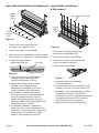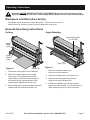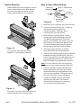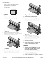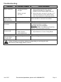
1
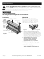
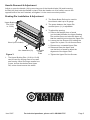
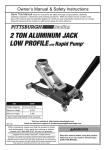
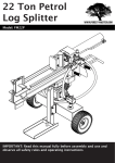
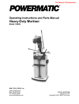
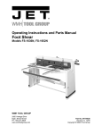
Owner’s Manual & Safety Instructions
Save This Manual Keep this manual for the safety warnings and precautions, assembly,
operating, inspection, maintenance and cleaning procedures. Write the product’s serial number in the
back of the manual near the assembly diagram (or month and year of purchase if product has no number).
Keep this manual and the receipt in a safe and dry place for future reference.
REV 15c
Visit our website at: http://www.harborfreight.com
Email our technical support at: [email protected]
When unpacking, make sure that the product is intact
and undamaged. If any parts are missing or broken,
please call 1-888-866-5797 as soon as possible.
Copyright© 1997 by Harbor Freight Tools®. All rights reserved.
No portion of this manual or any artwork contained herein may be reproduced in
any shape or form without the express written consent of Harbor Freight Tools.
Diagrams within this manual may not be drawn proportionally. Due to continuing
improvements, actual product may differ slightly from the product described herein.
Tools required for assembly and service may not be included.
Read this material before using this product.
Failure to do so can result in serious injury.
SAVE THIS MANUAL.
Specifications
Maximum Workpiece Width
Maximum Workpiece Thickness
Roll Diameter
Wire Forming Grooves
Die Sizes
30 IN.
20 Gauge
1-1/2 IN.
5/32, 11/64, and 7/32 IN.
1, 2, 3, 6, 8, and 10 IN.
WARNING SYMBOLS AND DEFINITIONS
This is the safety alert symbol. It is used to alert you to
potential personal injury hazards. Obey all safety messages
that follow this symbol to avoid possible injury or death.
Indicates a hazardous situation which, if not avoided,
will result in death or serious injury.
Indicates a hazardous situation which, if not avoided,
could result in death or serious injury.
Indicates a hazardous situation which, if not avoided,
could result in minor or moderate injury.
Addresses practices not related to personal injury.
Page 2
For technical questions, please call 1-888-866-5797.
Item 5907
Important Safety Information
WARNING Read all safety warnings and instructions.
Failure to follow the warnings and instructions may result in serious injury.
Save all warnings and instructions for future reference.
1. Work area safety
a.Keep work area clean and well lit.
Cluttered or dark areas invite accidents.
b.Keep children and bystanders
away while operating the tool.
Distractions can cause you to lose control.
2. Personal safety
a.Stay alert, watch what you are
doing and use common sense when
operating the tool. Do not use while
you are tired or under the influence
of drugs, alcohol or medication.
A moment of inattention while operating the
tool may result in serious personal injury.
b.Wear ANSI-approved safety goggles and
heavy-duty work cloves during use.
c.Do not overreach. Keep proper
footing and balance at all times.
This enables better control of the
tool in unexpected situations.
d.Dress properly. Do not wear loose
clothing or jewelry. Keep your hair,
clothing and gloves away from moving
parts. Loose clothes, jewelry or long
hair can be caught in moving parts.
3. Tool use and care
a.Do not force the tool. Use the correct
tool for your application. The correct tool
will do the job better and safer at the
rate for which it was designed.
b.Store idle tools out of the reach of
children and do not allow persons
unfamiliar with the tool or these
instructions to operate the tool. Tools are
dangerous in the hands of untrained users.
c.Maintain tools. Check for misalignment
or binding of moving parts,
breakage of parts and any other
condition that may affect the tool’s
operation. If damaged, have the tool
repaired before use. Many accidents
are caused by poorly maintained tools.
d.Keep cutting tools sharp and clean.
Properly maintained cutting tools with
sharp cutting edges are less likely
to bind and are easier to control.
e.Use the tool in accordance with these
instructions, taking into account the
working conditions and the work
to be performed. Use of the tool for
operations different from those intended
could result in a hazardous situation.
4. Service
a.Have your tool serviced by a qualified
repair person using only identical
replacement parts. This will ensure that
the safety of the tool is maintained.
5. The warnings, precautions, and instructions
discussed in this instruction manual cannot
cover all possible conditions and situations
that may occur. It must be understood by
the operator that common sense and caution
are factors which cannot be built into this
product, but must be supplied by the operator.
SAVE THESE INSTRUCTIONS.
Item 5907
For technical questions, please call 1-888-866-5797.
Page 3
Set up Instructions
Read the ENTIRE IMPORTANT SAFETY INFORMATION section at the beginning of this
manual including all text under subheadings therein before set up or use of this product.
Note: For additional information regarding the parts listed in the following pages,
refer to Parts List and Assembly Diagram near the end of this manual.
TO PREVENT SERIOUS INJURY:
Wear heavy duty gloves during setup and use. Keep hands clear
of the cutting, folding and rolling mechanisms.
Functions
Upper
Braking
Dies (12-01
to 12-06)
Mounting
Cover (33) over Rollers
Handle (18)
Apron (11)
Before use, mount the unit to a strong
level surface that is designed to handle the
weight of this machine, plus any additional
weight placed on it during use. If mounting
onto a bench or other wooden surface:
Upper
Blade
(23a)
Figure 2
Lower Blade (23b)
Work Bench (2)
Figure 1
Mounting Holes
1. Select four Bolts, eight Washers, and four
Nuts (not included) to accommodate the four
6mm holes on the Left and Right Frames (1,5).
Place the Press Brake in the location it will be
mounted in. Make a mark in the center of each
of the 4 mounting holes. Set the unit aside.
2. WARNING! Before drilling the holes,
make sure that there are no electric
wires, cables, utility lines or other
obstructions in the area to be drilled in.
3. Drill the holes straight down, large enough
to allow your mounting hardware to fit.
4. Put the Press Brake in place
and mount using the hardware.
Tighten all hardware securely before use.
Page 4
For technical questions, please call 1-888-866-5797.
Item 5907
Handle Removal & Adjustment
Adjust or move the Handle (18) by removing one of the Handle Knobs (26) and loosening
the Bolt (42) that holds the Handle in place. Slide the Handle out of its socket, move to the
opposite side of the tool if desired, and tighten it in the most convenient position.
Braking Die Installation & Adjustment
2. The Shear Brake Roll can be used to
bend sheet metal up to 20 gauge.
Upper Braking
Die (12-01
to 12-06)
3. The space between the Upper Die
and the Apron (11) is adjustable.
4. To adjust the spacing:
a. Place a flat straight piece of wood
(not included) between the Upper Braking
Die and the Apron and raise the Apron so
that the material just touches the Upper Die.
b. Loosen the Hex Screws (52) holding the
Upper Die in place. Do not remove them.
Wood (not included)
c. Remove any unneeded Upper Dies.
Hex Head Bolt (52)
Figure 3
Moveable
Cutter
Plate
d. Raise and lower the Apron and
use the block of wood to adjust the
alignment of the Upper Dies.
e. Tighten the Upper Die Hex Screws.
1. The Upper Braking Dies (12-01 to 12-06)
can be used for varying sizes of box and
pan forming. When forming a smaller box
or pan, choose the desired size Upper
Die, center it and remove the others.
Item 5907
For technical questions, please call 1-888-866-5797.
Page 5
Upper Blade Installation & Adjustment Lower Blade Installation
& Adjustment
Upper
Blade
(23a)
Hex Head Screw (58)
Lower
Blade
(23b)
Hex
Screws
(56)
Figure 4
1. Remove the Hex Screws (56) from
the Upper Cutting Blade (23a).
2. Remove the Upper Cutting Blade.
3. Align the Upper Cutting Blade so that it is flush
with the Apron (11) and secure with its Screws.
4. To adjust the Upper Blade:
Supporting Plate (22)
Nut (49)
Figure 5
1. Remove the Hex Screws (58) from
the Lower Cutting Blade (23).
2. Remove the Lower Cutting Blade.
3. Replace the Lower Cutting Blade and
secure with the Hex Screws.
4. To adjust the Lower Blade:
Figure 6
Hex Bolt (46)
a. Place a 30" piece of thin cardboard
or paper between the Upper and
Lower Cutting Blades (23a & b).
b. Rotate the Handle (18) and cut the
material. Use a straight edge to
determine the straightness of the cut
and if the Blade needs adjustment.
c. If the Blade is bowed out away from
the front of the tool, turn the adjustment
Nut (49) counterclockwise. This will
tighten the Supporting Plate (22) and
push the middle of the Upper Blade (23a)
out while pulling in its ends.
Figure 7
a. Lower the Upper Cutting Blade
to its lowest position.
b. Loosen the two inset Hex Head Bolts (59)
located on the top of the Work Bench (2).
c. Adjust the Lower Cutting Blade by turning
its Adjustment Screws. The distance
between the Lower Cutting Blade and Upper
Cutting Blade should be 5 to 8 percent
of the thickness of the workpiece.
d. Tighten the two inset Hex Head Bolts.
d. If the Blade is bowed in towards the
back of the tool, turn the adjustment Nut
clockwise. This will loosen the Supporting
Plate and pull the middle of the Upper
Blade in while pushing its ends out.
Page 6
For technical questions, please call 1-888-866-5797.
Item 5907
Operating Instructions
Read the ENTIRE IMPORTANT SAFETY INFORMATION section at the beginning of this
manual including all text under subheadings therein before set up or use of this product.
Workpiece and Work Area Set Up
Designate a work area that is clean and well-lit. The work area must not
allow access by children or pets to prevent distraction and injury.
General Operating Instructions
Cutting
Angle Bending
Upper Braking Die
(12-(01-06))
Upper
Blade
(23a)
Lower
Blade
(23b)
Apron (11)
Figure 8
Guide (16)
1. Scribe the cutting mark on the material.
2. Slide the material between the Upper
and Lower Cutting Blades so that the
Upper Blade is positioned directly above
the mark and the right hand side of the
material rests against the Guide (16).
3. While holding the material steady, rotate the
Handle until the material has been cut.
Item 5907
Figure 9
1. Mark the workpiece where you
want to bend the material.
2. Place the material above the Apron (11).
3. Align the bending mark with the front
edge of the Upper Braking Die.
4. Rotate the Handle (18) until the desired
angle has been formed. Use a protractor or
other measuring tool to ensure accuracy.
For technical questions, please call 1-888-866-5797.
Page 7
Radius Bending
Wire or Sheet Metal Rolling
Radius bending is most commonly used to
make cylinders and cones. Both shapes
are formed by making a series of small,
closely spaced bends in the workpiece.
Adjusting
Screw (27)
IN
Figure 12
Wire or Sheet Metal
32
31
24
Rollers
(24,31 & 32)
Roller
Adjustment
Knob (25)
1. Move the Cover (33) back and out of the way.
2. Coat the Pressing Rollers (24, 31 and 32)
with general purpose grease for
smooth operation. Clean any dirt or
excess grease from the Rollers.
3. Drop the Back Pressing Roller (24) by
loosening the Roller Adjusting Knob (25).
The Back Pressing Roll (24) forms the
radius in the material. The closer it is to the
front Rollers, the smaller the radius will be.
The Roller Adjustment Knob (25) adjusts
the spacing of the Back Pressing Roller.
Figure 10
For cylinders, the bends are evenly
spaced, i.e. every bend is identical.
4. Test with scrap metal first, as metals
have different bending characteristics.
5. Insert just the leading edge of your workpiece
between the Upper Pressing Roll (32) and
Lower Pressing Roll (31), and tighten the roll
bar gap Adjusting Screw (27) until the Roll
Bars are barely snug against the workpiece.
Note: For wire, insert the wire into the proper
sized groove in the Upper Pressing Roller (32).
6. Advance the Back Pressing Roll with the
Roller Adjustment Knob (25) as much as
desired depending on the tightness of the
roll to be accomplished. The tighter the roll,
the more the knobs must be advanced.
7. Rotate the Handle (18) until the proper
roll has been achieved. The material
should feed itself through the rollers as
you crank the Handle Assembly.
Figure 11
For cones, move one side of the stock out
farther than the other for every bend.
Page 8
For technical questions, please call 1-888-866-5797.
Item 5907
Pan Forming
Pans of various sizes can be formed
with a maximum lip (side) of 1".
To form a pan:
Figure 13
1. Pre-measure and cut the material
before bending. Notch the corners
according to the desired lip height.
Figure 16
4. Repeat Step 3 for the third side.
5. Rotate to the final side, and insert the
workpiece between the dies. The formed
sides will be on the outside of the Die.
Figure 14
2. Insert the material between the Upper
Braking Die and the Apron. Bend the material
until a 90º angle has been formed.
Figure 17
6. Before bending, tap one corner
nearer to the middle of the machine.
This will allow the material to clear the
Upper Braking Die when raised.
7. Bend the fourth side.
8. Using a block or piece of wood, tap the
corner of material back into place.
Pressing
Figure 15
3. Rotate the material 90º counterclockwise.
Allow the completed side to extend just
beyond the Die. Bend the second side.
1. Slide the Press Plate Bracket (8) of the
Press Plate Assembly into the receiver
holes of the Apron. Note that the
Press Plate (10) should be facing down.
2. Place the workpiece so that it is
centered under the Press Plate.
3. Rotate the Handle (18) to press the workpiece.
Item 5907
For technical questions, please call 1-888-866-5797.
Page 9
Maintenance and Servicing
Procedures not specifically explained in this manual must
be performed only by a qualified technician.
TO PREVENT SERIOUS INJURY FROM TOOL FAILURE:
Do not use damaged equipment. If abnormal noise or vibration occurs,
have the problem corrected before further use.
Cleaning, Maintenance, and Lubrication
1. BEFORE EACH USE, inspect the general condition of the tool.
Check for loose hardware, misalignment or binding of moving parts,
cracked or broken parts, and any other condition that may affect its safe operation.
2. Regularly grease all moving parts.
3. AFTER USE, wipe external surfaces of the tool with clean cloth.
Page 10
For technical questions, please call 1-888-866-5797.
Item 5907
Troubleshooting
Problem
Bend is distorted.
Possible Causes
2. Radius set back
too close.
Bend angle
doesn’t match
from end to end.
Likely Solutions
Bending
1. Clamping pressure
1. Adjust clamping pressure so that the
too tight.
workpiece has little or no clamping
pressure at the outside edges of the tool.
Clamp misaligned.
Metal doesn’t
cut evenly.
Upper Blade bowed.
Blades don’t cut
through metal.
1. Blades dull.
2. Blade distance
needs adjustment.
Rolled shape uneven Rollers misaligned.
from one end to
the other end.
2. Adjust the radius set back to at least 1-1/2
times the thickness of the material being
bent, then readjust the clamping pressure.
Measure angle at each end of bend, then adjust
radius set back on each side as needed.
Cutting
Turn Adjustment Nut clockwise to loosen
or counter clockwise to tighten.
CAUTION: Do not overtighten
Supporting Plate. Overtightening Supporting
Plate will cause permanent distortion.
1. Replace Blades.
2. Adjust distance of Lower Cutting Blade.
Rolling
Check and align rollers.
Follow all safety precautions whenever diagnosing or servicing the tool.
Disconnect power supply before service.
Item 5907
For technical questions, please call 1-888-866-5797.
Page 11
Parts List
Part
1
2
3
4
5
6
7
8
9
10
11
12-01
12-02
12-03
12-04
12-05
12-06
13
14
15
16
17
18
19
20
21
22
23a
23b
24
25
26
27
28
29
30
31
Page 12
Description
Left Frame
Work Bench
Crossbeam
Crank Arm
Right Frame
Bear Frame
Cover
Press Plate Bracket
Spring
Press Plate
Apron
Upper Braking Die 1"
Upper Braking Die 2"
Upper Braking Die 3"
Upper Braking Die 6"
Upper Braking Die 8"
Upper Braking Die 10"
Press Plate
Hex Head Bolt M10X65
Rolling Wheel
Guide
Adjustable Bolt
Handle
Positioning Bar
Positioner
Positioning Plate
Supporting Plate
Upper Cutting Blade
Lower Cutting Blade
Back Pressing Roller
Roller Adjuster Knob
Handle Knob
Adjusting Screw
Roll Bushing
Washer
Gear
Lower Pressing Roller
Qty
1
1
1
2
1
1
2
2
2
1
1
1
1
1
1
1
1
1
2
2
1
2
1
2
2
1
1
1
1
1
2
2
2
4
2
2
1
Part
32
33
34
35
36
37
38
39
40
42
43
44
45
46
47
48
49
50
51
52
53
54
55
56
57
58
59
62
63
64
65
66
67
68
69
70
71
Description
Upper Pressing Roller
Cover
Pressing Roll Lock
Eccentric Shaft
Washer
Roll Key
Hex Screw M6X12
Hex Screw M6X16
Hex Head Bolt M6X45
Hex Bolt
Hex Screw M6X8
Hex Head Bolt M10X55
Washer 10mm
Hex Head Bolt M12X100
Hex Screw M10X25
Washer 10mm
Nut M12
Hex Head Bolt M12X35
Hex Screw M10X35
Hex Screw M8X30
Hex Screw M10X30
Washer 10mm
Hex Screw M8X80
Hex Screw M6X12
Hex Screw M6X16
Hex Screw M6X12
Hex Screw M10X20
Oil Cup
Hose
Hex Wrench 8mm
Hex Wrench 5mm
Hex Wrench 6mm
Nut M12
Pin
Pin
Nut M10
Bolt
For technical questions, please call 1-888-866-5797.
Qty
1
1
1
2
2
2
4
2
2
4
2
2
2
1
2
2
1
2
2
9
4
2
2
7
2
7
2
2
2
1
1
1
2
2
2
2
2
Item 5907
Item 5907
71
71
66
26 70
7
42 38
26
70
65
18
64
39
44
29
45
35
15
4 25
27
33
40
62 36
34
28
28
1
24
19
67 47
17
37
32
42
48
20
31
68
3
30
51
49 50
46
43
28 68
28
67
6
70
55
12 -6 12 -5
13
21
37 30
48
8 9
47
53
22
12 -4
50
63
56
12 -3
69
51
40 36
12 -1
52
10
12 -2
11 54
14 23a
25
5 27
70
59
53
17
54
15
23b
14
45
2
7 38
29 39
35
4 62
55
44
8
58
42
9
59
16
57
Assembly Diagram
For technical questions, please call 1-888-866-5797.
Page 13
PLEASE READ THE FOLLOWING CAREFULLY
THE MANUFACTURER AND/OR DISTRIBUTOR HAS PROVIDED THE PARTS LIST AND ASSEMBLY
DIAGRAM IN THIS MANUAL AS A REFERENCE TOOL ONLY. NEITHER THE MANUFACTURER
OR DISTRIBUTOR MAKES ANY REPRESENTATION OR WARRANTY OF ANY KIND TO THE
BUYER THAT HE OR SHE IS QUALIFIED TO MAKE ANY REPAIRS TO THE PRODUCT, OR
THAT HE OR SHE IS QUALIFIED TO REPLACE ANY PARTS OF THE PRODUCT. IN FACT, THE
MANUFACTURER AND/OR DISTRIBUTOR EXPRESSLY STATES THAT ALL REPAIRS AND PARTS
REPLACEMENTS SHOULD BE UNDERTAKEN BY CERTIFIED AND LICENSED TECHNICIANS,
AND NOT BY THE BUYER. THE BUYER ASSUMES ALL RISK AND LIABILITY ARISING OUT OF
HIS OR HER REPAIRS TO THE ORIGINAL PRODUCT OR REPLACEMENT PARTS THERETO,
OR ARISING OUT OF HIS OR HER INSTALLATION OF REPLACEMENT PARTS THERETO.
Record Product’s Serial Number Here:
Note: If product has no serial number, record month and year of purchase instead.
Note: Some parts are listed and shown for illustration purposes only,
and are not available individually as replacement parts.
Page 14
For technical questions, please call 1-888-866-5797.
Item 5907
Limited 90 Day Warranty
Harbor Freight Tools Co. makes every effort to assure that its products meet high quality
and durability standards, and warrants to the original purchaser that this product is free from
defects in materials and workmanship for the period of 90 days from the date of purchase. This
warranty does not apply to damage due directly or indirectly, to misuse, abuse, negligence or
accidents, repairs or alterations outside our facilities, criminal activity, improper installation,
normal wear and tear, or to lack of maintenance. We shall in no event be liable for death,
injuries to persons or property, or for incidental, contingent, special or consequential damages
arising from the use of our product. Some states do not allow the exclusion or limitation of
incidental or consequential damages, so the above limitation of exclusion may not apply to
you. THIS WARRANTY IS EXPRESSLY IN LIEU OF ALL OTHER WARRANTIES, EXPRESS
OR IMPLIED, INCLUDING THE WARRANTIES OF MERCHANTABILITY AND FITNESS.
To take advantage of this warranty, the product or part must be returned to us with
transportation charges prepaid. Proof of purchase date and an explanation of the complaint
must accompany the merchandise. If our inspection verifies the defect, we will either repair or
replace the product at our election or we may elect to refund the purchase price if we cannot
readily and quickly provide you with a replacement. We will return repaired products at our
expense, but if we determine there is no defect, or that the defect resulted from causes not
within the scope of our warranty, then you must bear the cost of returning the product.
This warranty gives you specific legal rights and you may also
have other rights which vary from state to state.
Item 5907
For technical questions, please call 1-888-866-5797.
Page 15
3491 Mission Oaks Blvd. • PO Box 6009 • Camarillo, CA 93011 • 1-888-866-5797