1
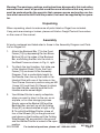
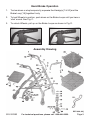
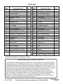
WALKER/STROLLER
WITH HAND BRAKE
02969
ASSEMBLY AND OPERATING INSTRUCTIONS
3491 Mission Oaks Blvd., Camarillo, CA 93011
Visit our Web site at http://www.harborfreight.com
Copyright © 2003 by Harbor Freight Tools®. All rights reserved. No portion of this manual or any
artwork contained herein may be reproduced in any shape or form without the express written consent
of Harbor Freight Tools.
For technical questions and replacement parts, please call 1-800-444-3353
Specifications
ITEM
Min. Handle Height
Max. Handle Height
Width, Front
Width, Back
Seat Height
Seat Dimensions
Wheel Dimensions
Weight Capacity
Accessories Included
Net Weight
DESCRIPTION
32-3/8”
36-3/4”
22-1/2” at Wheels
25-1/2” at Wheels
21-3/4” from Floor
12” L x 12” W x 1-1/8” Thick
5” Diameter x 7/8” W
225 Lbs. Max. (dead weight at rest)
Wire Basket, Removable Lining
15.10 Lbs.
Save This Manual
You will need the manual for the safety warnings and precautions, assembly
instructions, operating and maintenance procedures, parts list and diagram.
Keep your invoice with this manual. Write the invoice number on the inside of the
front cover. Keep the manual and invoice in a safe and dry place for future
reference.
Safety Warnings and Precautions
WARNING: When using this product, basic safety precautions should always
be followed to reduce the risk of personal injury and damage to equipment.
Read all instructions before using this product!
1.
Observe external conditions. Do not use this product in damp or wet
locations. Don’t expose to rain.
2.
Keep children away. This product is not a toy. Children must never be
allowed to play with, on, or around this product.
3.
Store idle equipment. When not in use, product must be stored in a dry
location to inhibit rust.
4.
Use the right product for the job. There are certain applications for which
this product was designed. It will do the job better and more safely at the rate
for which it was intended. Do not modify this product and do not use this
product for a purpose for which it was not intended.
5.
Dress properly. Do not wear loose clothing or jewelry that can be caught in
moving parts.
6.
Do not overreach. Keep proper footing and balance at all times.
REV 03d
SKU 02969
For technical questions, please call 1-800-444-3353.
Page 2
7.
Maintain product with care. Keep product clean and lubricated for better
and safer performance. Inspect periodically and, if any part appears broken
or damaged, have it repaired by an authorized technician. The handles must
be kept clean, dry, and free from oil and grease at all times.
8.
Stay alert. Watch what you are doing, use common sense. Do not operate
this product when you are tired.
9.
Check for damaged parts. Before using any product, any part that appears
damaged should be carefully checked to determine that it will operate
properly and perform its intended function. Check for alignment and binding
of moving parts; any broken parts or mounting fixtures; and any other
condition that may affect proper operation. Any part that is damaged should
be properly repaired or replaced by a qualified technician.
10. Replacement parts and accessories. When servicing, use only identical
replacement parts. Use of any other parts will void the warranty. Only use
accessories intended for use with this product.
11. Do not operate if under the influence of alcohol or drugs. Read warning
labels on prescriptions to determine if your judgment or reflexes are impaired
while taking drugs. If there is any doubt, do not operate the product.
12. Maintenance. For your safety, service and maintenance should be
performed regularly by a qualified technician.
Special Warnings for this Product
1.
Before use, be sure your Walker/Stroller is fully opened, the Seat is down
completely, and the folding bar beneath the Seat is in the locked position.
2.
Check that both Handles are at equal heights. If one is lower than the other,
adjust accordingly. Apply gentle pressure to the Handles to test the stability
of the Walker/Stroller before use.
3.
Test Brakes thoroughly before use. The brake bar on the wheels will prevent
the wheels from rolling, when the Brake is in the locked position (see Page
5, Hand Brake Operation). If the Wheels turn while Brakes are locked, have
the Brakes adjusted by an authorized technician. Under no circumstances
should you use this product if the Brakes do not lock properly.
4.
Always put Brakes in the locked position before sitting on the Seat. Do not sit
on the Seat unless you are on even, level ground.
5.
Check tires periodically, and replace when worn.
6.
This product is not a cart or a wheel chair. Do not use it to push or
carry people or objects. Do not load more than 25 Lbs. in the Basket.
SKU 02969
For technical questions, please call 1-800-444-3353.
Page 3
Warning: The warnings, cautions, and instructions discussed in this instruction
manual cannot cover all possible conditions and situations that may occur. It
must be understood by the operator that common sense and caution are factors which cannot be built into this product, but must be supplied by the operator.
Unpacking
When unpacking, check to make sure all parts listed on Page 6 are included.
If any parts are missing or broken, please call Harbor Freight Tools at the number
on the cover of this manual.
Assembly
All parts numbered and listed refer to those in the Assembly Diagram and Parts
List on Pages 5-6.
1.
2.
3.
Attach the Backrest Bar [7] to the Front
Frame [10] by depressing the two Brass
Buttons [8] on the sides of the Backrest
Bar, and sliding the Bar into the slots in
the Back Frame as shown in Fig. A, right.
To attach the two Handles, first slide one
of the Handrail Rods [3] into the Front
Frame [10] as shown in the Assembly
Diagram. Find a comfortable height for
the Handle, then line up the holes in the
Handrail Rod with one of the holes in the
Front Frame. Secure in position using an M6
Screw [42], and Knob [5]. Repeat to attach
the other Handle, making sure that both
Handles are the same height.
Backrest
Bar [7]
Fig. A, Attaching the Backrest Bar
Your Walker/Stroller is easily collapsible,
when you want to take it in the car, on an
airplane, or for other storage purposes.
Simply remove the Basket [49] and the
Backrest Bar, and pull up on the Folding
Strap [51] as demonstrated at right in Fig.
B. To unfold the Walker/Stroller, place all
four of the Wheels [22] on the ground and
push down on the Handles until the Folding
Side Braces [38] are parallel to the ground
and the Walker/Stroller is locked in the open
Fig. B, Collapsing the Walker/Stroller
position.
REV 04j; 07d
SKU 02969
For technical questions, please call 1-800-444-3353.
Page 4
Hand Brake Operation
1.
To slow down or stop temporarily, squeeze the Handgrip [1 & 52] and the
Brake Loop [1A] together firmly.
2.
To lock Wheels in position, push down on the Brake Loops until you hear a
‘click’ sound. See Fig. C.
3.
To unlock Wheels, pull up on the Brake Loops as shown in Fig. D.
Fig. C, Wheels in locked position
Fig. D, Wheels unlocked
Assembly Drawing
REV 04h; 04j
SKU 02969
For technical questions, please call 1-800-444-3353.
Page 5
Parts List
ITEM
DESCRIPTION
1
1A
2
3
4
5
6
7
8
9
10
11
12
13
14
15
16
17
18
19
20
21
22
23
24
25
Left Handgrip w/thumb rest
Brake Loop
Control Plate
Handrail Rod
Braking Thread
Knob
Low Density Foam
Backrest Bar
8.15 Brass Button
1.6 Spring
Front Frame
Plastic Washers
M6 Defended Loose Nut
Spring Mat
Wheel Fork Bearing Cap
60012 Bearing
Wheel Fork
Screws
M12 Defended Loose Nut
M8 Screws
Washers
6082 Bearing
5” Bearing Wheel
M8 Defended Loose Nut
Screw Cap
M8 Screws
QTY
ITEM
DESCRIPTION
QTY
1
2
2
2
2
2
1
1
2
2
1
10
8
2
2
4
2
2
2
2
6
8
4
6
8
2
26
Screws (Left & Right)
27
Brake Piece
28
Control Piece (Left)
29
Control Piece (Right)
30
Fixed Ring
31
M5 Defended Loose Nut
32
M5 Crossed Screw
33
Screws
34
Link Rod
35
L-Shape Joining
36
37 Crossed Screws
37
Arc Screws
38
Folding Side Braces
39
Slide Plug
40
40 Crossed Screws
41
Brass Tube
42
M6 Screws
43
7/8” Collar
44
Back Frame
45
Plastic Tie
46
3/16” Screws
47
Clip
48
Padded Seat
49
Basket
50
PVC Bag
51
Folding Strap
52
Right Handgrip w/thumb rest
NOTE: Some parts are listed and shown for illustration purposes only and are not
available individually as replacement parts.
1
1
1
1
2
4
4
2
1
2
4
6
2
2
2
2
2
2
1
2
4
2
1
1
1
1
1
PLEASE READ THE FOLLOWING CAREFULLY
THE MANUFACTURER AND/OR DISTRIBUTOR HAS PROVIDED THE PARTS DIAGRAM
IN THIS MANUAL AS A REFERENCE TOOL ONLY. NEITHER THE MANUFACTURER NOR
DISTRIBUTOR MAKES ANY REPRESENTATION OR WARRANTY OF ANY KIND TO THE
BUYER THAT HE OR SHE IS QUALIFIED TO MAKE ANY REPAIRS TO THE PRODUCT OR
THAT HE OR SHE IS QUALIFIED TO REPLACE ANY PARTS OF THE PRODUCT. IN FACT,
THE MANUFACTURER AND/OR DISTRIBUTOR EXPRESSLY STATES THAT ALL
REPAIRS AND PARTS REPLACEMENTS SHOULD BE UNDERTAKEN BY CERTIFIED
AND LICENSED TECHNICIANS AND NOT BY THE BUYER. THE BUYER ASSUMES ALL
RISK AND LIABILITY ARISING OUT OF HIS OR HER REPAIRS TO THE ORIGINAL
PRODUCT OR REPLACEMENT PARTS THERETO, OR ARISING OUT OF HIS OR HER
INSTALLATION OF REPLACEMENT PARTS THERETO.
SKU 02969
REV 04h; 04j
For technical questions, please call 1-800-444-3353.
Page 6