1
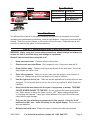
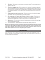
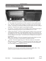
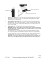
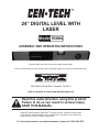
24” DIGITAL LEVEL WITH
LASER
Model 93884
Assembly And Operating Instructions
Diagrams within this manual may not be drawn proportionally.
Due to continuing improvements, actual product may differ slightly from the product described herein.
3491 Mission Oaks Blvd., Camarillo, CA 93011
Visit our website at: http://www.harborfreight.com
Read this material before using this product.
Failure to do so can result in serious injury.
Save this manual.
Copyright© 2006 by Harbor Freight Tools®. All rights reserved. No portion of this manual
or any artwork contained herein may be reproduced in any shape or form without the
express written consent of Harbor Freight Tools.
For technical questions or replacement parts, please call 1-800-444-3353.
Labels
DANGER
Specifications
AVOID EXPOSURELaser radiation is emitted
from this aperture.
LASER RADIATION
AVOID DIRECT EYE EXPOSURE
Laser Dot Accuracy
Up to 98 Feet
Laser Line Accuracy Up to 33 Feet
Vial Accuracy
+/- .3 Degrees
Power Source
“AAA” Batteries (Qty. 2),
9V Battery (Qty. 1)
Power Output: <=5mW,
Wavelength: 650 nm
CLASS IIIa LASER PRODUCT
This product complies with
21 CFR 1040.10 and 1040.11
CEN-TECH
3491 Mission Oaks Blvd.,
Camarillo, CA, USA, 93011
Manufacture Date:___________, _____
Save This Manual
You will need the manual for the safety warnings and precautions, assembly instructions,
operating and maintenance procedures, parts list and diagram. Keep your invoice with this
manual. Write the invoice number on the inside of the front cover. Keep the manual and
invoice in a safe and dry place for future reference.
Safety Warnings and Precautions
WARNING: When using tool, basic safety precautions should always be followed to
reduce the risk of personal injury and damage to equipment.
Read all instructions before using this tool!
1.
Keep work area clean. Cluttered areas invite injuries.
2.
Observe work area conditions. Don’t expose to rain. Keep work area well lit.
3.
Keep children away. Children must never be allowed in the work area. Do not let
them handle the Laser Level.
4.
Store idle equipment. When not in use, tools must be stored in a dry location to
inhibit rust. Always lock up tools and keep out of reach of children.
.
Use the right tool for the job. There are certain applications for which this tool was
designed. Do not modify and do not use this tool for a purpose for which it was not
intended.
6.
Never direct the laser beam into the eyes of any person or animal. THIS MAY
CAUSE SEVERE INJURY TO THE EYE. Do not look into the beam during operation. Make certain to switch the Laser Level to “OFF” when making adjustments
or changing the batteries. Laser light, when reflected off a mirror like surface can
cause serious eye damage.
.
Only use the type of battery recommended in this manual. Use only “AAA”
batteries for the Laser, and a 9V battery for the digital display. Do not mix old
and new batteries.
8.
Maintain tools with care. Keep tools clean for better and safer performance.
SKU 93884
For technical questions, please call 1-800-444-3353
Page 9.
Stay alert. Watch what you are doing, use common sense. Do not operate any tool
when you are tired.
10.
Check for damaged parts. Before using any tool, any part that appears damaged
should be carefully checked to determine that it will operate properly and perform its
intended function. Any part that is damaged should be properly repaired or replaced
by a qualified technician. Do not use the tool if any switch does not turn On and Off
properly.
11.
Replacement parts and accessories. When servicing, use only identical replacement parts. Use of any other parts will void the warranty.
12.
Do not operate tool if under the influence of alcohol or drugs. Read warning
labels if taking prescription medicine to determine if your judgment or reflexes are
impaired while taking drugs. If there is any doubt, do not operate the tool.
13.
Maintenance. For your safety, service and maintenance should be performed regularly by a qualified technician.
14.
Use fresh batteries. Weak batteries could affect the visibility of this tool.
Warning: The warnings, cautions, and instructions discussed in this instruction manual
cannot cover all possible conditions and situations that may occur. It must be understood by the operator that common sense and caution are factors which cannot be
built into this product, but must be supplied by the operator.
Unpacking
When unpacking, check to make sure that the product is intact and undamaged. If any
parts are missing or broken, please call Harbor Freight Tools at the number on the cover of
this manual as soon as possible.
SKU 93884
For technical questions, please call 1-800-444-3353
Page Operation
Refer to the Assembly Drawing on Page 6.
LCD Display Controls
ON/OFF
HOLD
0% Calibrate
))
)
1.
On/Off: Holding this button down for several seconds turns the LCD display on or
off. The display will automatically shut off after a period to conserve battery power.
2.
Hold: This button keeps the same reading on the display, even if the level’s angle
changes. Everything on the display will flash except the number while the reading is
being held. Press the button again to stop holding the reading.
3.
0% (percent): This button switches the LCD display between displaying the angle in
degrees and displaying the angle as a percent difference from 0° or 90°.
4.
Calibrate (Zero Setting): This button toggles between reading 0 at the current angle
and reading the actual angle. Press the “Calibrate” button once to change the current reading to 0° or 0%. Press the “Calibrate” button again and hold it to restore the
level to reading the actual angle. The level will reset to reading the actual angle if it
is switched off.
Note: Actual calibration of the level (changing the actual angle setting) is not done
by this button and needs to be performed by a qualified technician.
.
Sound: This button toggles the sound. When the sound is on, the level will
beep once when it measures any 10° increment and more than once when it reads
0° or 90°. A symbol – • )) – will appear above the decimal point on the display and
the unit will beep to indicate that the sound is on.
)
))
)
Horizontal and Vertical Vial Use
The Vials (9, 10) on the level can be read by observing the bubble within. If the
bubble is centered in between the lines, then the Vial is level.
REV 07g
SKU 93884
For technical questions, please call 1-800-444-3353
Page Laser Controls
Slide Switch (18)
Vertical Laser Button (12)
Horizontal/Dot Laser Button (12)
1.
Vertical Laser Button (12) - This button turns on the vertical laser line if the Slide
Switch (18) is in the upper position. The vertical laser is blocked while the Slide
Switch (18) is in the lower position.
2.
Horizontal/Dot Laser Button (12) - This button turns on the horizontal laser line if
the Slide Switch (18) is in the upper position. It can be used along with the vertical
laser line to make a cross. When the Slide Switch (18) is in the lower position, the
laser is a dot instead.
3.
Slide Switch (18) - The Slide Switch (18) determines laser operation.
WARNING! Point the end of the level away from people’s eyes when adjusting
the Slide Switch (18). If the Slide Switch is in the lower position, it can conceal
an illuminated laser beam.
If the Slide Switch (18) is in the upper position, the Vertical Laser Button will project a vertical line and the Horizontal/Dot Laser Button will project a horizontal line.
When the Slide Switch (18) is in the lower position, the Vertical Laser Button will be
covered and the Horizontal/Dot Laser Button will project a simple dot beam.
WARNING! To conserve battery power and prevent accidents, move the Slide
Switch (18) to the upper position and verify that both lasers are off after use.
REV 07g
SKU 93884
For technical questions, please call 1-800-444-3353
Page Maintenance
1.
Wipe the Level clean with a lint free cloth when needed.
2.
Store the Level in a dry location where it will not freeze or overheat.
3.
Before each use, inspect the Level to make sure nothing is cracked or broken. Do
not use the Level if anything is cracked or broken. Have it repaired by a qualified
service technician.
Changing or Installing Batteries
FIGURE 2
Battery Polarity
Direction
End Cap (14)
1.
To change the “AAA” batteries that power the Laser, remove the End Cap (14) and
set it aside. See FIGURE 2, above.
2.
Remove the old batteries and replace them with two fresh batteries. Make sure that
you match up the positive (+) and negative (-) ends to the diagram on the side of the
level. See FIGURE 2, above. Replace the End Cap (14).
FIGURE 3
Battery Cover (16)
9 Volt Battery
3.
To change the 9 Volt battery that powers the LCD (3), remove the Battery Cover (16)
by first removing the Screw (15).
4.
Install a fresh battery making sure you match up the positive (+) and negative (-)
terminals as shown inside the battery compartment. Replace the Battery Cover (16)
and the Screw (15). See FIGURE 3, above.
SKU 93884
For technical questions, please call 1-800-444-3353
Page Parts List
Part
1
2
3
4
5
6
Description
Laser Diode
End Cap 1
LCD
On/Off Button
Hold Button
0% (Percent) Button
Part
7
8
9
10
11
12
Description
Calibrate Button
Sound Button
Horizontal Dial
Vertical Vial
Body
Laser On/Off Buttons
Part
13
14
15
16
17
18
Description
“AAA” Battery (Qty. 2)
End Cap 2
Screw
Battery Cover
9 Volt Battery
Slide Switch
Assembly Drawing
18
PLEASE READ THE FOLLOWING CAREFULLY
THE MANUFACTURER AND/OR DISTRIBUTOR HAS PROVIDED THE PARTS DIAGRAM IN THIS MANUAL
AS A REFERENCE TOOL ONLY. NEITHER THE MANUFACTURER NOR DISTRIBUTOR MAKES ANY
REPRESENTATION OR WARRANTY OF ANY KIND TO THE BUYER THAT HE OR SHE IS QUALIFIED TO
MAKE ANY REPAIRS TO THE PRODUCT OR THAT HE OR SHE IS QUALIFIED TO REPLACE ANY PARTS
OF THE PRODUCT. IN FACT, THE MANUFACTURER AND/OR DISTRIBUTOR EXPRESSLY STATES THAT
ALL REPAIRS AND PARTS REPLACEMENTS SHOULD BE UNDERTAKEN BY CERTIFIED AND LICENSED
TECHNICIANS AND NOT BY THE BUYER. THE BUYER ASSUMES ALL RISK AND LIABILITY ARISING OUT
OF HIS OR HER REPAIRS TO THE ORIGINAL PRODUCT OR REPLACEMENT PARTS THERETO, OR ARISING OUT OF HIS OR HER INSTALLATION OF REPLACEMENT PARTS THERETO.
Note: Some parts are listed and shown for illustration purposes only and are not available
individually as replacement parts.
SKU 93884
For technical questions, please call 1-800-444-3353
Page