1
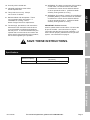
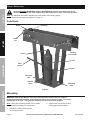
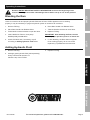
Owner’s Manual & Safety Instructions
SaveThis
ThisManual
ManualKeep
Keep
manual
safety
warnings
and
precautions,
assembly,
Save
thisthis
manual
forfor
thethe
safety
warnings
and
precautions,
assembly,
operating,
operating,maintenance
inspection, maintenance
cleaning procedures.
Write the
product’s
themanual
inspection,
and cleaning and
procedures.
Write the product’s
serial
numberserial
in thenumber
back ofinthe
back
the manual
near the
month ifand
year of
purchase if product has no number).
near
theofassembly
diagram
(or assembly
month anddiagram
year of (or
purchase
product
has
no number). Keep this manual and
thisinmanual
and dry
the place
receiptforinfuture
a safereference.
and dry place for future reference.
theKeep
receipt
a safe and
REV 15e
Visit our website at: http://www.harborfreight.com
Email our technical support at: [email protected]
When unpacking, make sure that the product is intact
and undamaged. If any parts are missing or broken,
please call 1-888-866-5797 as soon as possible.
Copyright© 2015 by Harbor Freight Tools®. All rights reserved.
No portion of this manual or any artwork contained herein may be reproduced in
any shape or form without the express written consent of Harbor
Freight Tools.
Harbor Freight Tools.
Diagrams within this manual may not be drawn proportionally. Due to continuing
improvements, actual product may differ slightly from the product described herein.
Tools required for assembly and service may not be included.
Read this material before using this product.
Failure to do so can result in serious injury.
SAVE THIS MANUAL.
Table of Contents
Safety.......................................................... 2
Setup........................................................... 4
Operation..................................................... 5
Maintenance................................................ 2
Parts List and Diagram................................ 7
Warranty..................................................... 12
Safety
WARNING SYMBOLS AND DEFINITIONS
This is the safety alert symbol. It is used to alert you to potential
personal injury hazards. Obey all safety messages that
follow this symbol to avoid possible injury or death.
Indicates a hazardous situation which, if not avoided,
will result in death or serious injury.
Indicates a hazardous situation which, if not avoided,
could result in death or serious injury.
Indicates a hazardous situation which, if not avoided,
could result in minor or moderate injury.
Setup
Addresses practices not related to personal injury.
IMPORTANT SAFETY INFORMATION
Read all safety warnings and all instructions.
Failure to heed these markings may result in personal injury and/or property damage.
Operation
1. Attach pipe bender securely to solid, flat and level
surface that can support weight of pipe bender
and pipe, with enough clearance for movement
of pipe. Do not lay pipe bender on its side. The
hydraulic ram may leak or not function properly.
9. Wear ANSI-approved safety goggles,
heavy-duty work gloves, and steel-toe
work boots during set up and/or use.
2. Keep hands away from ram, pipe
and rollers during use.
11. Do not leave the pipe bender
unattended when loaded.
3. To prevent injury from burns, do
not apply heat to pipe.
12. Do not adjust safety valve.
4. Use only on free standing pipe. Do not
use on pipe that is part of an assembly
or that is installed into a structure.
Maintenance
5. Study, understand, and follow all instructions
before operating this device.
6. Keep rollers clean. If pipe rests on obstruction,
it creates an uneven surface, causing
excess stress and possible breakage.
7. Do not use on painted pipe or
pipe that has debris on it.
8. STOP and release compression if you suspect
imminent structural failure. If safe, inspect
thoroughly and reposition pipe before proceeding.
Page 2
10. Keep bystanders out of work area.
13. Inspect before every use; do not use
if parts are loose, damaged.
14. Ram service must be performed only by
qualified repair personnel. Service or
maintenance performed by unqualified
personnel could result in a risk of injury.
15. When servicing a ram, use only identical
replacement parts . Use of unauthorized
parts or failure to follow maintenance
instructions may create a risk of injury.
16. No alterations shall be made to this product.
17. Only use with accessories rated to handle the
forces exerted by this tool during operation. Other
accessories not designed for the forces generated
may break and forcefully launch pieces.
For technical questions, please call 1-888-866-5797.
Item 35336
23. WARNING: The brass components of this product
contain lead, a chemical known to the State
of California to cause cancer and birth defects
or other reproductive harm. (California Health
& Safety Code § 25249.5, et seq.)
19. Industrial applications must follow
OSHA requirements.
20. This product is not a toy. Keep it
out of reach of children.
24. WARNING: This product contains di (2-ethylhexyl)
phthalate (DEHP), a chemical known to the State
of California to cause cancer and birth defects
or other reproductive harm. (California Health
& Safety Code § 25249.5, et seq.)
21. Maintain labels and nameplates. These
carry important safety information. If
unreadable or missing, contact
Harbor Freight Tools for a replacement.
22. The warnings, precautions, and instructions
discussed in this instruction manual cannot
cover all possible conditions and situations
that may occur. It must be understood by the
operator that common sense and caution are
factors which cannot be built into this product,
but must be supplied by the operator.
Safety
18. Use only with included ram.
IMPORTANT! Before first use:
Check hydraulic fluid level and fill to 1/4″ below the
fill port as needed - see instructions on page 5.
Thoroughly test the Ram for proper operation. If it
does not work properly, bleed air from its hydraulic
system - see instructions on page 5.
Setup
SAVE THESE INSTRUCTIONS.
Specifications
Maximum Capacity
Schedule 40 or 80 malleable steel pipe
Maintenance
Operation
Pipe Type
16 Tons
(32,000 lb)
Item 35336
For technical questions, please call 1-888-866-5797.
Page 3
Setup - Before Use:
Read the ENTIRE IMPORTANT SAFETY INFORMATION section at the beginning of this
manual including all text under subheadings therein before set up or use of this product.
Safety
Note: For additional information regarding the parts listed in the following pages,
refer to Parts List and Assembly Diagram on page 10.
Functions
R-Pin
(on back)
Roller
2"
2-1/2" 1-1/2"
3"
Setup
Cotter
Pin
1-1/4"
1"
3/4"
1/2"
1/2" 3/4"
1"
2"
1
1-1/4" -1/2" 2-1/2"
3"
Fill Plug
(on back)
Piston
Ram
Operation
Ram
Handle
Fulcrum
Mounting
Hole
Release
Valve
Mounting
Hole
Figure A
Maintenance
Mounting
WARNING! Attach Pipe Bender securely to solid and level surface that can support
weight of Pipe Bender and pipe, with enough clearance for movement of pipe. Do not lay
pipe bender on its side. The hydraulic ram may leak and not function properly.
Note: Verify that mounting surface has no hidden
components before drilling or driving bolts.
2. Mount base to mounting surface
using appropriate hardware.
1. Use base to mark mounting holes
on mounting surface.
Page 4
For technical questions, please call 1-888-866-5797.
Item 35336
Operating Instructions
Read the ENTIRE IMPORTANT SAFETY INFORMATION section at the beginning of this
manual including all text under subheadings therein before set up or use of this product.
Safety
Bleeding the Ram
BEFORE EACH USE OR IF RAM PERFORMANCE DECREASES,
check for excessive air and proper hydraulic fluid level in Ram. If Ram appears not to be working
properly, it may be necessary to purge its hydraulic system of excessive air as follows:
6. Place Ram Handle over Release Valve.
2. Place Ram Handle over Release Valve.
7. Twist the Handle clockwise to close Valve.
3. Twist Handle counterclockwise to open the Valve.
8. Replace Fill Plug.
4. Insert Handle into Fulcrum, then pump
Handle quickly several times.
IMPORTANT: After bleeding the Ram, test the
Ram for proper operation prior to its actual use.
5. Check fluid level and, if necessary, top off
according to Adding Hydraulic Fluid below.
9. If, after bleeding, the Ram does not appear
to be working properly, do not use it until
repaired by a qualified service technician.
Setup
1. Remove Fill Plug.
Adding Hydraulic Fluid
1. Remove Fill Plug.
3. Replace Fill Plug.
Maintenance
Operation
2. Add high grade hydraulic fluid (sold separately)
slowly until the fluid reaches 1/4″
below the top of the Fill Port.
Item 35336
For technical questions, please call 1-888-866-5797.
Page 5
Bending Pipe
NOTICE: A certain amount of deformation will occur when using this Pipe Bender.
Choosing the right pipe will reduce deformation. Use only ANSI Schedule 40 or 80 malleable steel pipe.
Safety
Note: To further reduce deformation,
internal support may be provided by:
a. Using mandrels. Follow mandrel
manufacturer’s directions.
2. Attach Bending Die to Piston.
3. Adjust Rollers to correspond with
size of Bending Die:
a. Remove R-Pins from Cotter Pins,
then remove Cotter Pins.
b. Packing pipe with clean sand, then
capping off ends with steel caps
(sold separately) before bending.
WARNING! To prevent injury from
burns, do not apply heat to pipe.
Setup
NPS
Pipe OD
(Nominal Pipe Size) (Outside Diameter)
(inches)
(inches)
1/2
0.840
3/4
1.050
1
1.315
1-1/4
1.660
1-1/2
1.900
2
2.375
2-1/2"
2.88
3"
3.50
b. Move Rollers to proper positions, then
replace Cotter Pins and R-Pins.
1/2"
Bending Die
Rollers set
to 1/2"
1/2"
2"
2"
2-1/2" 1-1/2"
3"
1-1/4"
1-1/2" 2-1/2"
1"
3/4"
1/2"
1/2"
3/4"
1"
1-1/4"
3"
Piston
Figure B
Note: Practice on scrap workpieces until
familiar with Pipe Bender’s capabilities.
Operation
1. Choose Bending Die the same nominal pipe size
as pipe. For example: Use 1/2" Bending Die
with the size marked on it with 1/2" NPS pipe.
Note: Outside pipe diameters are larger
than the pipe size. See Figure B.
Figure C
Maintenance
Page 6
For technical questions, please call 1-888-866-5797.
Item 35336
Note: Use only with pipe that fits the bending
die exactly. Pipe will deform significantly if
it does not fit the Bending Die exactly.
4. Mark center line of bend on pipe.
5. Slide pipe into Bending Die, lining up center line
marked on pipe with center of Bending Die.
2"
2"
1-1/4"
1"
3/4"
1/2"
1/2"
3/4"
1"
1-1/2" 2-1/2"
3"
1-1/4"
Safety
2-1/2" 1-1/2"
3"
1/2"
Setup
1/2" NPS
Pipe
Figure D
8. Insert Handle into Fulcrum, then pump
Handle until pipe reaches Bending Die.
2"
2-1/2" 1-1/2"
3"
1-1/4"
1"
3/4"
1/2"
1/2"
3/4"
1"
2"
1-1/2" 2-1/2"
3"
1-1/4"
Figure E
10. Place Ram Handle over Release Valve.
11. Twist Handle counterclockwise to open
the Valve and lower the piston.
Item 35336
12. Remove pipe. If necessary, remove
Roller(s) to allow room to remove pipe.
13. After use, store indoors out of reach of children.
For technical questions, please call 1-888-866-5797.
Page 7
Maintenance
7. Twist Handle clockwise to close Valve.
Operation
9. Continue pumping slowly until desired angle is
reached. Keep in mind that pipe may rebound
slightly, so you may need to bend very slightly
beyond your desired bend to get the correct
bend. Practice on scrap workpieces first.
6. Place Ram Handle over Release Valve.
User-Maintenance Instructions
Procedures not specifically explained in this manual must
be performed only by a qualified technician.
Safety
TO PREVENT SERIOUS INJURY FROM TOOL FAILURE:
Do not use damaged equipment. If abnormal noise or vibration
occurs, have the problem corrected before further use.
1. BEFORE EACH USE, inspect the general condition
of the Pipe Bender and Ram. Check for:
• loose hardware,
• misalignment or binding of moving parts,
• cracked or broken parts,
• any condition that may affect its safe operation.
Setup
If a problem occurs, have the problem corrected
before further use.
Do not use damaged equipment.
2. BEFORE EACH USE, thoroughly test the Ram
for proper operation prior to its actual use.
If the Ram appears not to be working properly,
follow Bleeding instructions on page 5.
3. AT LEAST ONCE EVERY THREE YEARS,
change the hydraulic fluid:
a. Remove Ram from Pipe Bender
by removing two Bolts (3).
b. With the Ram fully lowered, remove the Fill Plug.
c. Tip the Ram over to allow the old
hydraulic fluid to drain out completely.
Dispose of the old hydraulic fluid in
accordance with local regulations.
d. With the Ram upright, completely fill the
Hydraulic Unit with high grade hydraulic fluid until
the fluid is 1/4″ below the top of the Fill Port.
e. Turn the Release Knob counterclockwise
to open the Release Valve.
f. Pump the Handle up and down quickly
several times to purge air from the system.
g. Recheck fluid level and re-fill as needed.
h. Replace the Fill Plug.
i. Replace Ram on Pipe Bender.
Operation
4. AFTER EACH USE, wipe with a clean cloth.
Store indoors out of children’s reach.
Maintenance
Page 8
For technical questions, please call 1-888-866-5797.
Item 35336
TO PREVENT SERIOUS INJURY:
Use caution when troubleshooting a malfunctioning ram.
Completely resolve all problems before use. If the solutions presented in the Troubleshooting guide do not
solve the problem, have a qualified technician inspect and repair the ram before use.
After the ram is repaired: Test it carefully without a load by raising it and lowering it fully,
checking for proper operation, BEFORE RETURNING THE RAM TO OPERATION.
Safety
Troubleshooting
DO NOT USE A DAMAGED OR MALFUNCTIONING RAM!
POSSIBLE SYMPTOMS
Fluid
leaking
from filler
plug
X
Check that Release Valve is closed fully.
Valves may be blocked and may not
close fully. To flush the valves:
1. Lower the piston and securely close the Release Valve.
2. Manually lift the piston several inches.
3. Open the release valve and force the
piston down as quickly as possible.
X
X
PROBABLE SOLUTION
(Make certain that the Ram is not supporting
a load while attempting a solution.)
Setup
Handle
moves up
when ram
is under
load
Ram may be low on fluid. Check the
fluid level and refill if needed.
X
Ram may require bleeding - see instructions on page 5.
Unit may have too much hydraulic fluid inside,
check fluid level and adjust if needed.
Maintenance
X
Operation
Pump
Piston will
stroke feels not lift all
spongy
the way
Item 35336
For technical questions, please call 1-888-866-5797.
Page 9
Parts List and Assembly Diagram
PLEASE READ THE FOLLOWING CAREFULLY
Safety
THE MANUFACTURER AND/OR DISTRIBUTOR HAS PROVIDED THE PARTS LIST AND ASSEMBLY DIAGRAM
IN THIS MANUAL AS A REFERENCE TOOL ONLY. NEITHER THE MANUFACTURER OR DISTRIBUTOR
MAKES ANY REPRESENTATION OR WARRANTY OF ANY KIND TO THE BUYER THAT HE OR SHE IS
QUALIFIED TO MAKE ANY REPAIRS TO THE PRODUCT, OR THAT HE OR SHE IS QUALIFIED TO REPLACE
ANY PARTS OF THE PRODUCT. IN FACT, THE MANUFACTURER AND/OR DISTRIBUTOR EXPRESSLY
STATES THAT ALL REPAIRS AND PARTS REPLACEMENTS SHOULD BE UNDERTAKEN BY CERTIFIED AND
LICENSED TECHNICIANS, AND NOT BY THE BUYER. THE BUYER ASSUMES ALL RISK AND LIABILITY
ARISING OUT OF HIS OR HER REPAIRS TO THE ORIGINAL PRODUCT OR REPLACEMENT PARTS
THERETO, OR ARISING OUT OF HIS OR HER INSTALLATION OF REPLACEMENT PARTS THERETO.
Parts List
Part
Setup
1
2
3
4
5
6
7
8
Description
Frame
Ram
Hex Bolt
Cotter Pin
Roller
R-Pin
1/2" Bending Die
3/4" Bending Die
Qty
1
1
2
2
2
2
1
1
Part
9
10
11
12
13
14
15
Description
1" Bending Die
1-1/4" Bending Die
1-1/2" Bending Die
2" Bending Die
2-1/2" Bending Die
3" Bending Die
Ram Handle
Qty
1
1
1
1
1
1
1
Operation
Maintenance
Record Product’s Serial Number Here:
Note: If product has no serial number, record month and year of purchase instead.
Note: Some parts are listed and shown for illustration purposes only,
and are not available individually as replacement parts.
Page 10
For technical questions, please call 1-888-866-5797.
Item 35336
Maintenance
Operation
Setup
Safety
Assembly Diagram
Item 35336
For technical questions, please call 1-888-866-5797.
Page 11
Limited 90 Day Warranty
Harbor Freight Tools Co. makes every effort to assure that its products meet high quality and durability standards,
and warrants to the original purchaser that this product is free from defects in materials and workmanship for the
period of 90 days from the date of purchase. This warranty does not apply to damage due directly or indirectly,
to misuse, abuse, negligence or accidents, repairs or alterations outside our facilities, criminal activity, improper
installation, normal wear and tear, or to lack of maintenance. We shall in no event be liable for death, injuries
to persons or property, or for incidental, contingent, special or consequential damages arising from the use of
our product. Some states do not allow the exclusion or limitation of incidental or consequential damages, so the
above limitation of exclusion may not apply to you. THIS WARRANTY IS EXPRESSLY IN LIEU OF ALL OTHER
WARRANTIES, EXPRESS OR IMPLIED, INCLUDING THE WARRANTIES OF MERCHANTABILITY AND FITNESS.
To take advantage of this warranty, the product or part must be returned to us with transportation charges
prepaid. Proof of purchase date and an explanation of the complaint must accompany the merchandise.
If our inspection verifies the defect, we will either repair or replace the product at our election or we may
elect to refund the purchase price if we cannot readily and quickly provide you with a replacement. We will
return repaired products at our expense, but if we determine there is no defect, or that the defect resulted
from causes not within the scope of our warranty, then you must bear the cost of returning the product.
This warranty gives you specific legal rights and you may also have other rights which vary from state to state.
3491 Mission Oaks Blvd. • PO Box 6009 • Camarillo, CA 93011 • 1-888-866-5797