1
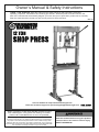
Owner’s Manual & Safety Instructions
Save This Manual Keep this manual for the safety warnings and precautions, assembly,
operating, inspection, maintenance and cleaning procedures. Write the product’s serial number in the
back of the manual near the assembly diagram (or month and year of purchase if product has no number).
Keep this manual and the receipt in a safe and dry place for future reference.
REV 15d
Visit our website at: http://www.harborfreight.com
Email our technical support at: [email protected]
When unpacking, make sure that the product is intact
and undamaged. If any parts are missing or broken,
please call 1-888-866-5797 as soon as possible.
Copyright© 2009 by Harbor Freight Tools®. All rights reserved.
No portion of this manual or any artwork contained herein may be reproduced in
any shape or form without the express written consent of Harbor Freight Tools.
Diagrams within this manual may not be drawn proportionally. Due to continuing
improvements, actual product may differ slightly from the product described herein.
Tools required for assembly and service may not be included.
Read this material before using this product.
Failure to do so can result in serious injury.
SAVE THIS MANUAL.
Table of Contents
Safety
Safetye��������������������������������������������������������� 2
Specifications...............................................
Setup........................................................... 4
Operationa���������������������������������������������������� 8
Maintenancei����������������������������������������������� 9
Parts List and Diagram............................... 10
Warranty..................................................... 12
WARNING SYMBOLS AND DEFINITIONS
Setup
This is the safety alert symbol. It is used to alert you to potential
personal injury hazards. Obey all safety messages that
follow this symbol to avoid possible injury or death.
Indicates a hazardous situation which, if not avoided,
will result in death or serious injury.
Indicates a hazardous situation which, if not avoided,
could result in death or serious injury.
Indicates a hazardous situation which, if not avoided,
could result in minor or moderate injury.
Addresses practices not related to personal injury.
Operation
IMPORTANT SAFETY INFORMATION
WARNING Read all safety warnings and instructions. Failure to heed these markings may result in
personal injury and/or property damage. Save all warnings and instructions for future reference.
The warnings, precautions, and instructions discussed in this manual cannot cover all possible
conditions and situations that may occur. The operator must understand that common sense and
caution are factors, which cannot be built into this product, but must be supplied by the operator.
Maintenance
1. Keep hands away from Arbor Plates
and Press Pin during use.
6. Avoid off-center loads. Do not operate if
workpiece tilts or binds during compression.
2. Do not move workpiece while compressed.
7. STOP and release compression if you suspect
imminent structural failure. If safe, inspect
thoroughly and reposition before proceeding.
3. Release load before service or maintenance.
4. Bolt to floor before use.
5. Keep area under Arbor Plates clear. If Arbor
Plates rest on obstruction (i.e. bolt, debris,
etc.), it creates an uneven press, causing
excess stress and possible breakage.
8. Do not compress springs or other elastic
objects. They could disengage hazardously.
9. Wear ANSI-approved safety goggles,
heavy-duty work gloves, and steel-toe
work boots during set up and/or use.
10. Keep bystanders out of work area.
Page 2
For technical questions, please call 1-888-866-5797.
Item 33497
17. Use only with Ram included with this Press.
13. Inspect before every use; do not use
if parts are loose or damaged.
18. Industrial applications must follow
OSHA requirements.
14. Ram service must be performed only by
qualified repair personnel. Service or
maintenance performed by unqualified
personnel could result in a risk of injury.
19. This product is not a toy. Keep it
out of reach of children.
15. When servicing a Ram, use only identical
replacement parts – refer to attached, productspecific parts list and diagram. Follow
instructions in the “User - Maintenance
Instructions” section of this manual. Use of
unauthorized parts or failure to follow maintenance
instructions may create a risk of injury.
Safety
12. Do not operate the hydraulic ram
beyond rated capacity.
16. Only use with accessories rated to handle the
forces exerted by this tool during operation. Other
accessories not designed for the forces generated
may break and forcefully launch pieces.
20. Maintain labels and nameplates on the
Shop Press. These carry important safety
information. If unreadable or missing, contact
Harbor Freight Tools for a replacement.
21. The warnings, precautions, and instructions
discussed in this instruction manual cannot
cover all possible conditions and situations
that may occur. It must be understood by the
operator that common sense and caution are
factors which cannot be built into this product,
but must be supplied by the operator.
Maintenance
Operation
SAVE THESE INSTRUCTIONS.
Setup
11. Do not stand directly in front of the
press when loaded. Do not leave the
press unattended when loaded.
Item 33497
For technical questions, please call 1-888-866-5797.
Page 3
Specifications
Maximum Capacity
Fluid Type
12 Tons (24,000 pounds)
Hydraulic Fluid
Safety
Note: For additional information regarding the parts listed in the following pages, refer
to the Parts List and Assembly Diagram near the end of this manual.
Setup
Setup - Before Use:
Read the ENTIRE IMPORTANT SAFETY INFORMATION section at the beginning of this
manual including all text under subheadings therein before set up or use of this product.
Operation
Inspect tool before use, looking for damaged, loose, and missing parts. If any problems are found, do not
use tool until repaired.
Components of this Shop Press are heavy. You will need a helper to safely assemble this product.
Note: For additional information regarding the parts listed in the following pages,
refer to the Assembly Diagram near the end of this manual.
Assembly
1. Using the Functions section and the Parts List
and Diagram near the end of the manual, lay
out and identify all pieces before assembly.
Maintenance
2. Have a helper hold the Uprights (15) vertically, and
hold them steady until the Spreader (16) and Base
Supports (14) are secured in place. See Figure A.
Uprights (15)
Bolts (12)
Spreader (16)
Nuts (13)
Page 4
3. Slide each Base Support under the Uprights, and
place the Spreader between them, as shown
above. Line up the bolt holes and insert the
Bolts (12) through the Spreader, Base Supports and
Uprights, then secure in place with the Nuts (13).
4. Determine where you want to use the Press. Check
to ensure that the Uprights are perpendicular
to the Base Supports, then bolt to the floor
(see Mounting to the Floor on page 6).
Nuts (13)
Base Supports (14)
Figure A
For technical questions, please call 1-888-866-5797.
Item 33497
Assembly (cont′d)
Nuts (2)
Bolts
(3)
Uprights (15)
Figure B
6. Slide the Support Pins (11) into the holes in the
Uprights. Angle the Press Apron (10) so the
rails of the Press Apron straddle the Uprights,
then lower into place so the Press Apron
rests on the Support Pins. See Figure C.
Upright (15)
Eye Bolts (6)
Safety
Ram Ring
Header (1)
7. Insert the Eye Bolts (6) into the holes in
the Ram Plate (7) and secure in place
with the Nuts (8). See Figure D.
Ram Plate (7)
Nuts (8)
Figure D
8. Place the Arbor Plates (9) on the Press Apron.
Angle the Ram Plate (7) the same way you placed
the Press Apron and slide it down the Press Frame
so it rests on the Arbor Plates. See Figure E.
Upright (15) Ram Plate (7)
Setup
5. Align the holes on the Ram Ring Header (1)
with the holes in the top of the Uprights
and secure in place with the Bolts (3) and
Nuts (2). Check that the assembly is square
then finish tightening bolts. See Figure B.
Press Apron (10)
Figure C
Pins (11)
9. Bleed the Ram (see Bleeding the Ram on page
8) and make sure it is fully collapsed.
Maintenance
Note: For set-up, position the Support Pins at least
several holes down from the top holes in the Uprights so
you have room to place the Ram Plate (7). You can readjust the placement of the Press Apron after assembly.
Figure E
Operation
Arbor
Plate
(9)
Item 33497
For technical questions, please call 1-888-866-5797.
Page 5
Hang the Ram
1. Hang the Springs (4) on the bars of
the Ram Ring Header (1). See .
Safety
2. Place the Ram (5) on the center
of the Ram Plate (7).
4. Hook the Springs (4) into the Eye Bolts (6)
to secure the Ram/Ram Plate in place.
Ram Ring Header (1)
Springs (4)
3. Slide the Ram Plate up the Ram Ring
Header (1) so the Ram Saddle fits in the
bracket (center underside of top of Header).
Ram (5)
Ram
Plate
(7)
Eye Bolts (6)
Figure F
Mounting to the Floor
Setup
1. To mount the Shop Press, with assistance, move the
unit to the location where it is to be used. If needed,
drill four 1/2" diameter mounting holes in the feet
and use as a template to mark the spots where four
1/2" diameter holes will be drilled in the concrete or
wood floor. Check for any hidden wiring or cables
and adjust the location for the holes as needed.
Then, temporarily set the Shop Press aside.
2. Use a masonry drill bit to drill the four 1/2"
diameter holes (about 3"-4" deep) into
the concrete. Make sure to blow out the
concrete dust from the drilled holes.
3. Set the Shop Press back to the location where
it is to be used, and align the four 1/2" diameter
mounting holes in its feet with the four pre-drilled
1/2" holes in the concrete or wood. Then use
four minimum 3" long, 1/2" diameter, concrete
anchor bolts or lag bolts (not included) to secure
the Shop Press to the concrete or wood floor.
Operation
Maintenance
Page 6
For technical questions, please call 1-888-866-5797.
Item 33497
Functions
Safety
Upper
Beam
Ram
Ram
Handle
Setup
Ram
Plate
Operation
Frame
Posts
Arbor
Plates
Maintenance
Press
Apron
Base Sections
Item 33497
For technical questions, please call 1-888-866-5797.
Page 7
Operating Instructions
Read the ENTIRE IMPORTANT SAFETY INFORMATION section at the beginning of this
manual including all text under subheadings therein before set up or use of this product.
Safety
Bleeding the Ram
IMPORTANT! Before first use, check for proper
hydraulic fluid level in the Ram. Then thoroughly test
the Ram for proper operation prior to its actual use. If
the Ram appears not to be working properly, it may be
necessary to bleed its hydraulic system of excess air.
To bleed the Ram:
1. Remove the Fluid Filler Plug. Insert the slot on
the lower portion of the Handle over the Valve
Release Screw. Turn the Handle counterclockwise
to close the Valve Release Screw. See Figure G.
2. Insert the Handle into the Plunger/Fulcrum
Assembly. Apply pressure to the Saddle, and
pump the Handle quickly several times.
3. Check the Fluid Fill Hole and, if necessary, top
off the Fluid Fill Hole with hydraulic fluid.
4. Replace the Fluid Filler Plug.
5. Test the Ram several times before putting into use.
If, after purging, the Ram still does not appear to
be working properly, do not use the Ram until it has
been repaired by a qualified service technician.
Setup
Handle (17) Elevating
Screw
(some models)
Plunger/
Fulcrum
Saddle
Fluid Fill
Hole
Operation
Valve
Release
Screw
Fluid Filler
Plug
Figure G
Tool Set Up
1. Use the Support Pins (11) to adjust the
height of the Press Apron (10).
2. Position the Press Apron as high as possible
while positioning the workpiece as close as
possible to the ram of the Ram Plate (7).
WARNING: Keep area under Arbor Plates
clear of stray bolts or debris. Such items
create an uneven surface which can cause
the Arbor Plates to break under pressure.
Workpeice Set Up
Maintenance
WARNING: When pressing two items together, the items must be lined up vertically.
If not, one item may forcefully eject sideways from the unit.
Page 8
For technical questions, please call 1-888-866-5797.
Item 33497
1. Place the item to press between the Arbor Plates (9).
2. Using the Ram Handle (17), jack down the
Ram Plate until the ram of the Ram Plate
contacts your workpiece. If you are pressing
two items together, line them up vertically.
3. Continue to operate the Handle
to press the workpiece.
4. When the task is completed, carefully release the
Ram pressure. For safety, remove the Handle,
and use it to slowly turn the Valve Release Screw
on the Ram, allowing the Ram Plate to rise.
WARNING: Stay clear of the rising Ram. The Ram
may rise quickly during the release process.
5. Clean, then store the tool indoors
out of children’s reach.
Safety
General Operating Instructions
Maintenance and Servicing
Procedures not specifically explained in this manual must
be performed only by a qualified technician.
Setup
TO PREVENT SERIOUS INJURY FROM ACCIDENTAL OPERATION:
Turn the Power Switch of the tool off before performing any procedure in this section.
TO PREVENT SERIOUS INJURY FROM TOOL FAILURE:
Do not use damaged equipment. If abnormal noise or vibration
occurs, have the problem corrected before further use.
Cleaning, Maintenance, and Lubrication
• loose hardware,
• misalignment or binding of moving parts,
• cracked or broken parts, and
• any other condition that may
affect its safe operation.
2. BEFORE EACH USE, test the Ram (5) for
proper operation. If the Ram appears not
to be working properly, follow instructions
in Bleeding the Ram on page 8.
3. AFTER USE, wipe external surfaces
of the tool with clean cloth.
Hydraulic Fluid
1. With the Ram fully lowered, unhook the
Springs from the Eye Bolts and remove
the Ram from the Shop Press.
2. Remove the Fluid Filler Plug.
3. Tip the Ram to allow the old hydraulic fluid to drain
out of the unit completely, and dispose of the old
hydraulic fluid in accordance with local regulations.
Item 33497
4. Completely fill the unit with a high quality
hydraulic fluid (not included) until the fluid just
begins to run out of the Fluid Fill Hole.
5. Reinstall the Fluid Filler Plug.
6. Clean with a clean cloth using a
detergent or mild solvent.
7. Replace the Ram onto the Shop Press
(See Hang the Ram on page 6).
For technical questions, please call 1-888-866-5797.
Maintenance
Change the hydraulic fluid at least once every
three years. To change the hydraulic fluid:
Operation
1. BEFORE EACH USE, inspect the general
condition of the tool. Check for:
Page 9
Troubleshooting
Safety
TO PREVENT SERIOUS INJURY:
Use caution when troubleshooting a malfunctioning Ram.
Completely resolve all problems before use. If the solutions presented in the Troubleshooting guide do not solve
the problem, have a qualified technician inspect and repair the Ram before use.
After the Ram is repaired: Test it carefully without a load by raising it and lowering it fully, checking for
proper operation, BEFORE RETURNING THE RAM TO OPERATION.
DO NOT USE A DAMAGED OR MALFUNCTIONING RAM!
POSSIBLE SYMPTOMS
Ram will not
function at
its weight
capacity
Saddle
lowers
under
load
X
X
Setup
X
Pump
stroke
feels
spongy
Handle
Saddle will moves
not lift all
up when
the way
Ram is
under load
Check that Release Valve is closed fully.
X
X
X
X
PROBABLE SOLUTION
Fluid
(Make certain that the Ram is not
leaking
supporting a load while attempting a
from filler solution.)
plug
X
Operation
X
Valves may be blocked and may not
close fully. To flush the valves:
1. Lower the Saddle and securely
close the Release Valve.
2. Manually lift the saddle
several inches.
3. Open the release valve and force the
saddle down as quickly as possible.
Ram may be low on fluid. Check
the fluid level and refill if needed.
Ram may require bleeding - see
instructions on page page 8.
Unit may have too much hydraulic
fluid inside, check fluid level
and adjust if needed.
Parts List and Diagram
Parts List
Part
Maintenance
1
2
3
4
5
6
7
8
9
Description
Ram Ring Header
Nut M12
Bolt M12×110
Spring
Ram
Eye Bolts
Ram Plate
Nut M8
Arbor Plate
Qty
1
4
4
2
1
2
1
2
2
Part
10
11
12
13
14
15
16
17
Description
Qty
Press Apron
Support Pin
Bolt M10×30
Nut M10
Base Supports
Uprights
Spreader
Handle
1
2
4
4
2
2
1
1
Record Product’s Serial Number Here:
Note: If product has no serial number, record
month and year of purchase instead.
Page 10
Note: Some parts are listed and shown for
illustration purposes only, and are not available
individually as replacement parts.
For technical questions, please call 1-888-866-5797.
Item 33497
Assembly Diagram
2
2
2
Safety
3
2
3
3
3
4
4
5
6
7
6
15
10
11
11
12
12
13
13
Item 33497
12
13
12
13
16
14
14
For technical questions, please call 1-888-866-5797.
Page 11
Operation
8
9
8
9
15
Setup
17
Maintenance
1
PLEASE READ THE FOLLOWING CAREFULLY
THE MANUFACTURER AND/OR DISTRIBUTOR HAS PROVIDED THE PARTS LIST AND ASSEMBLY DIAGRAM
IN THIS MANUAL AS A REFERENCE TOOL ONLY. NEITHER THE MANUFACTURER OR DISTRIBUTOR
MAKES ANY REPRESENTATION OR WARRANTY OF ANY KIND TO THE BUYER THAT HE OR SHE IS
QUALIFIED TO MAKE ANY REPAIRS TO THE PRODUCT, OR THAT HE OR SHE IS QUALIFIED TO REPLACE
ANY PARTS OF THE PRODUCT. IN FACT, THE MANUFACTURER AND/OR DISTRIBUTOR EXPRESSLY
STATES THAT ALL REPAIRS AND PARTS REPLACEMENTS SHOULD BE UNDERTAKEN BY CERTIFIED AND
LICENSED TECHNICIANS, AND NOT BY THE BUYER. THE BUYER ASSUMES ALL RISK AND LIABILITY
ARISING OUT OF HIS OR HER REPAIRS TO THE ORIGINAL PRODUCT OR REPLACEMENT PARTS
THERETO, OR ARISING OUT OF HIS OR HER INSTALLATION OF REPLACEMENT PARTS THERETO.
Limited 90 Day Warranty
Harbor Freight Tools Co. makes every effort to assure that its products meet high quality and durability standards,
and warrants to the original purchaser that this product is free from defects in materials and workmanship for the
period of 90 days from the date of purchase. This warranty does not apply to damage due directly or indirectly,
to misuse, abuse, negligence or accidents, repairs or alterations outside our facilities, criminal activity, improper
installation, normal wear and tear, or to lack of maintenance. We shall in no event be liable for death, injuries
to persons or property, or for incidental, contingent, special or consequential damages arising from the use of
our product. Some states do not allow the exclusion or limitation of incidental or consequential damages, so the
above limitation of exclusion may not apply to you. THIS WARRANTY IS EXPRESSLY IN LIEU OF ALL OTHER
WARRANTIES, EXPRESS OR IMPLIED, INCLUDING THE WARRANTIES OF MERCHANTABILITY AND FITNESS.
To take advantage of this warranty, the product or part must be returned to us with transportation charges
prepaid. Proof of purchase date and an explanation of the complaint must accompany the merchandise.
If our inspection verifies the defect, we will either repair or replace the product at our election or we may
elect to refund the purchase price if we cannot readily and quickly provide you with a replacement. We will
return repaired products at our expense, but if we determine there is no defect, or that the defect resulted
from causes not within the scope of our warranty, then you must bear the cost of returning the product.
This warranty gives you specific legal rights and you may also have other rights which vary from state to state.
3491 Mission Oaks Blvd. • PO Box 6009 • Camarillo, CA 93011 • 1-888-866-5797