1
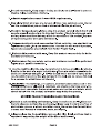
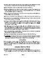
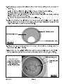
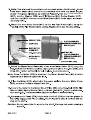
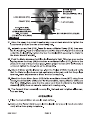
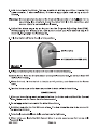
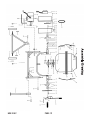
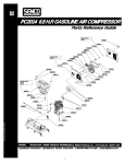
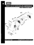
 CENTRAL MACHINERY | _
MINI CEMENT MIXER
1.25 CU. FT.
Моде!
ASSEMBLY AND OPERATING INSTRUCTIONS
Visit our website at: http://www.harborfreight.com
Read this material before using this product.
Failure to do so can result in serious injury.
SAVE THIS MANUAL.
Copyright® 2004 by Harbor Freight Tools®. All rights reserved. No portion of this manual or any artwork contained herein
may be reproduced in any shape or form without the express written consent of Harbor Freight Tools. Diagrams within
this manual may not be drawn proportionally. Due to continuing improvements, actual product may differ slightly from the
product described herein. Tools required for assembly and service may not be included.
For technical questions or replacement parts, please call 1-800-444-3353.
PRODUCT SPECIFICATIONS
Item Description
Drum Capacity 1.25 Cubic Feet GB
Drum Opening 10" Diameter A US
Input Power: 1/4 HP 187912
Motor RPM: 1200
Voltage: 110 VAC at 60HZ
Overall Dimensions | 45-1/2" x 21" x 42"
Weight 62 Lbs
SAVE THIS MANUAL
You will need this manual for the safety warnings and precautions,
assembly, operating, inspection, maintenance and cleaning procedures,
parts list and assembly diagram. Keep your invoice with this manual. Write
the invoice number on the inside of the front cover. Keep this manual and
invoice in a safe and dry place for future reference.
GENERAL SAFETY WARNINGS AND PRECAUTIONS
1. Keep work area clean and dry. Cluttered, damp, or wet work areas invite
Injuries.
2. Keep children away from work area. Do not allow children to handle or climb
on or in this product.
3. Store idle equipment. When not in use, tools and equipment should be stored
in a dry location to inhibit rust. Always lock up tools and equipment, and keep
out of reach of children.
4. Do not use this product if under the influence of alcohol or drugs. Read
warning labels on prescriptions to determine if your judgement or reflexes are
impaired while taking drugs. If there is any doubt, do not attempt to use this
product.
5. Dress safely. Do not wear loose clothing or jewelry, as they can become
caught in moving parts. Wear a protective hair covering to prevent long hair
from becoming caught in moving parts. If wearing a long-sleeve shirt, roll
sleeves up above elbows.
SKU 91907 PAGE 2
6. Do not overreach. Keep proper footing and balance at all times to prevent
tripping, falling, back injury, etcetera.
7. Industrial applications must follow OSHA requirements.
8. Stay alert. Watch what you are doing at all times. Use common sense. Do not
use this product when you are tired or distracted from the job at hand.
9. Check for damaged parts. Before using this product, carefully check that it will
operate properly and perform its intended function. Check for damaged parts
and any other conditions that may affect the operation of this product. Replace
or repair damaged or worn parts immediately.
10. Replacement parts and accessories: When servicing, use only identical
replacement parts. Only use accessories intended for use with this product.
Approved accessories are available from Harbor Freight Tools.
11. Maintain this product with care. Keep this product clean and dry for better
and safer performance.
12. Maintenance: For your safety, service and maintenance should be performed
regularly by a qualified technician.
13. Use the right tool for the job. Do not attempt to force a small tool or attach-
ment to do the work of a larger industrial tool. There are certain applications for
which this tool was designed. It will do the job better and more safety at the
rate for which it was intended. Do not modify this tool, and do not use this tool
for a purpose for which it was not intended.
14. WARNING! The warnings, precautions, and instructions discussed in this
manual cannot cover all possible conditions and situations that may occur. The
operator must understand that common sense and caution are factors, which
cannot be built into this product, but must be supplied by the operator.
SPECIFIC PRODUCT WARNINGS AND PRECAUTIONS
1. Maintain a safe working environment. Keep the work area well lit. Make sure
there is adequate surrounding workspace. Always keep the work area free of
obstructions, grease, oil, trash, and other debris. Do not use the Cement Mixer
in areas near flammable chemicals, dusts, and vapors.
2. Always place the Cement Mixer on a solid, flat, level, surface that is
capable of supporting the weight of the Mixer and its load.
SKU 91907 PAGE 3
3. Keep a safe clearance around the Cement Mixer. Keep all people (except
the operator) a minimum of six feet from the Mixer during operation.
4. Keep all guards in place and in proper working condition.
5. Remove adjusting tools, shovels, hand trowels, etc. Make sure all adjusting
tools, shovels, hand trowels, and other tools and equipment are removed from
the Cement Mixer prior to turning it on.
6. Never stick your hands and/or tools into the Drum Assembly while the
Cement Mixer is in operation.
7. Do not overload the Cement Mixer. An overload may damage the equipment.
8. Do not move the Cement Mixer during operation. The Mixer could tip over
or the Engine could be damaged.
9. Use eye and hand protection. Wear ANSI approved safety impact eye
goggles and heavy-duty work gloves when using the Cement Mixer. ANSI
approved safety impact eye goggles and heavy-duty work gloves are available
from Harbor Freight Tools.
10.Prolonged exposure to noise levels above 85 dBA is hazardous to
hearing. Always wear ANSI approved hearing protection when operating or
working near the Cement Mixer while it is running. ANSI approved hearing
protectors are available from Harbor Freight Tools.
11. Prior to using the Cement Mixer, make sure you read and completely
understand this instruction manual.
12. Keep the Cement Mixer and surrounding area clean at all times.
13. WARNING! People with pacemakers should consult with their physician(s)
before using this product. Operation of equipment in close proximity to a heart
pacemaker could cause interference or failure of the pacemaker.
UNPACKING
When unpacking, check to make sure that all components are included. Refer to
the assembly drawing on the last page. If any parts are missing or broken, please
call Harbor Freight Tools at the number shown on the cover of this manual as
soon as possible.
ASSEMBLY INSTRUCTIONS
Assemble Stand (Recommend 2 people assist in assembly)
1. Place Stand (#1) into Hinge Bracket (#2) so that bolt holes line up as shown in
Figure A. (Also see photo on cover page and Assembly Drawing on last page).
SKU 91907 PAGE 4
2. Insert Hex Bolts (#60 & #40) through holes from one side, then Flat Washer
(#45) & Spring Washer (#44) and Hex Nut (#43) from the other side, and
tighten with a wrench.
3. Insert Support Bracket (#3) onto Stand (#1) so that bolt holes line up.
4. Insert Hex Bolts (#60 & #40) through holes from one side, then Flat Washer
(#45) & Spring Washer (#44) and Hex Nut (#43) from the other side, and
tighten with a wrench.
STAND (#1) р,
Hex Bolt (#40) î Hex Bolt (#60)
Hex Bolt (#60) 1 Flat Washer (#45) q Flat Washer (#45)
| Spring Washer (#44) Spring Washer (#44)
Flat Washer (#45) | pring Hex Nut (#43
Spring Washer (#44) Hex Nut (#43) ex Nut (#43)
Hex Nut (#43)
HINGE BRACKET (#2) SUPPORT BRACKET
(#3)
5. Secure Wheels (#4) in place using Flat Washer (#5) and Lock Nut (#7).
6. Insert Shaft Pins (#6) into the Hinge Bracket (2) axle holes, outside each Lock
Nut (#7).
HINGE BRACKET (#2)
LOCK NUT (#7)
Flat WASHER (#5) SPLIT PIN (#6)
FIGURE B
SKU 91907 PAGE 5
7. Bend each side of the Pins outward so they do not fall out.
8. With two people, set Lower Drum (#35) with attached Support Arm (#27)
assembly into Stand assembly. See photo below.
SUPPORT ARM (#27)
HEX BOLT (#40) r HEX BOLT (#40)
FLAT WASHER (#45) TH SR E FLAT WASHER (#45)
EE | SPRING WASHER (#44)
SPRING WASHER (#44) , HEX NUT (#43)
HEX NUT (#43)
FIGURE
9. Insert Hex Bolts (#40) through holes from one side, then Flat Washer (#45)
and Spring Washer (#44) and then Hex Nut (#43) from the other side, tighten
with a wrench.
10. Mount Degree Adjusting Plate (#32) to Iron Tube Fixture (#21) using two Hex.
Bolts (#58) from the outside. Secure from the inside with a Flat Washer (#45),
Spring Washer (#44), then Hex. Nut (#43).
HEX. BOLT (#58)
IRON TUBE
FIXTURE (#21)
— DEGREE ADJUSTING Arm (#33)
GRIP ASSEMBLY (#62)
HEX. BOLT (#39)
FLAT WASHER (#55)
SPRING WASHER (#42)
HEX Nut (#41)
HEX. BOLT
(#39) HEX. NUT (#41)
FLAT WASHER (#55)
SPRING (#34) SPRING WASHER ( #42)
DEGREE ADJUSTING PLATE (#32)
FIGURE D
SKU 91907
PAGE 6
11. Attach Degree Adjust Arm (#33) to Iron Tube Fixture (#21) shaft as shown in
Figure D.
a.) Insert Spring (#34) into lower hole of Degree Adjusting Arm (#33).
b.) Press down on Arm until holes align on the pivot shaft.
c.) Insert the Hex. Bolt (#39) and secure with Flat Washer (#55), Spring
Washer (#42) and Hex Nut (#41).
d.) Tighten to a point where the Arm can still move.
12. Glue the Rubber Seal (#36) to the Upper Drum (#37) (glue not included)
making sure that the holes in both align. The Rubber Seal must be flat on the
Upper Drum (#37) to ensure a proper seal.
MOUNTING HOLE
UPPER DRUM (#37)
RUBBER SEAL (#36)
FIGURE E
13. Place the Upper Drum (#37) on the Lower Drum (#35), making sure the
mounting holes align in both.
14. Insert the six, Hex. Bolts (#56) into each mounting hole. Secure each Bolt
with a Flat Washer (#46) and Spring Washer (#47) and Hex. Nut (#48).
UPPER DRUM (#37)
HEX BOLT (#56) 4
FLAT WASHER (#46) DC MIXER BLADE
SPRING WASHER (#47) dni (838)
HEX. NUT (#48) a —
(TYPICAL OF SIX PLACES) ‘
FIGURE F
SKU 91907 PAGE 7
15. Note: You will need the assistance of a second person for this step. Mount
each Mixer Blade (#38) inside the assembled drum with the Blade angled
about 10 degrees clockwise as shown in Figure F. Use the Cross-head bolt
(#53), Leather Washer (#54), and Flat Washer (#46) Spring Washer (#47)
and Hex Nut (#48) to secure each Mixer Blade (#38) to the upper and lower
mounting holes.
16. Mount the inner Motor Cover (#17) to the Iron Tube Fixture (#21) using the
Hex Bolt (#58), Flat Washer (#45), Spring Washer (#44) and Hex Nut (#43).
O
jale
HEX BOLT (#58) Do emiten
SHAFT (#24)
FLAT WASHER (#45)
SPRING WASHER (#44)
HEX NUT (#43)
INNER MOTOR
COVER (#17)
i I HEX. BOLT (#57) STRAP (#9)
> FLAT WASHER (#46)
>> MOTOR MOUNT SPRING WASHER (#47)
PLATE (#8) HEX NUT (#48)
FIGURE G SUPPORT PIPE (#63)
17. Attach the Motor Mount Plate (#8) to the Inner Motor Cover (#17) using the
Hex. Bolt (#57),Flat Washer (#46), Spring Washer (#47) Hex. Nut (#48), and
Strap (#9). Tighten sufficiently to hold in place. See photo above.
Note: Once the Motor (#12) is mounted, the Motor Mount Plate (#8) must be
adjusted up or down to tighten the Belt.
18. Place the Motor (#12), attached to the power cable to the outer Motor Cover
(#15), on top of the Motor Mount Plate (#8).
19. Secure the motor to the Motor Mount Plate (#8) using Hex. Bolt (#59), Flat
Washer (#45) Spring Washer (#44), and Hex. Nut (#43). Tighten all four Hex.
Nuts hand-tight. The Motor will be adjusted forward or backward later.
20. Squarely push Pulley (#16) center onto the shaft (#24) so that the groove in
the pulley engages the Flat pin (#22). The Pulley (#16) should be flush with the
step on the shaft.
Caution: Do not pound the Pulley onto the shaft. Damage can occur causing a
loose fit.
SKU 91907 PAGE 8
MOTOR COVER
MOUNTING
HOLES (TYPICAL OF 3)
LOCK SCREW (#13) SHAFT (#24)
PULLEY (#16) FLAT KEY (#22)
HEX. BOLT (#59)
PAT Bo of
FLAT WASHER (#45) Pu.
SPRING WASHER (#44) “
HEX. NUT (#43) Poo”
(TYPICAL OF 4 PLACES)
FIGURE H
21. Once the pulley is pushed in all the way, use an Allen wrench to tighten the
Lock Screw (#13) on the side of the Pulley hub.
22. Install the pulley Belt (#18). Place Belt around Motor Pulley (#10), then over
the Pulley (#16). Push the Motor inward until the Motor Pulley (#10) is directly
under the Pulley (#16). Tighten the four Hex Bolts (#59) securing the Motor to
the Motor Mount Plate (#8).
23. Push the Motor downward until the Belt tension is tight. This step may require
tapping down the Strap (#9) behind the Inner Motor Cover (#17). Refer to the
photo at the top of the previous page. When proper tension (1/4" deflection) is
achieved, tighten the Hex. Nuts on the Strap (#9).
24. Check if Motor and belt turns true. Turn the Pulley (#16) by hand and verify
that the Motor pulley does not rub against any other part, and that the pulleys
turn true. make adjustments to Motor location as required.
25. Mount the Outer Motor Cover (#15) to the Inner Motor Cover (#17) using three
Cross-Head Hex Bolts (#49) and Flat Washer (#46), Spring Washer (#47) and
Hex Nuts (#48). Make sure that the power cord from the Motor to the Switch
Assembly (#14) does not come in contact with moving parts.
26. The Cement Mixer assembly is complete. Go back and retighten all screws,
nuts and bolts.
OPERATION
1. Place the Cement Mixer on a solid, even surface.
2. Connect the Power Cord to an electrical outlet (or properly rated extension
cord) with a three prong receptacle.
SKU 91907 PAGE 9
3. Add material to the Drum. Typical maximum mixing quantities include: 3/4
gallons water, 1 shovel cement, 5 shovels aggregate rook using a size 3
shovel.
Warning: Do not attempt to move the Cement Mixer when it is full and / or in
operation. It is unsafe to move the mixer while in this condition, and
severe injury to personnel could occur.
4. Adjust the drum angle by pulling out on the Degree Adjusting Arm (#33),
Disengaging the locking pins, and push on Arm until the desired angle is
reached. Re-engage the locking pins.
5. Flip the Switch (#14) to the (I) or On position.
SWITCH (#14)
OUTER MOTOR COVER (#15)
6. Filling and emptying the Drum is best done with the Drum Rotating.
Caution: Never leave the Cement Mixer running while unattended. Do not turn Mixer Off
while full of cement.
7. When finished, flip the Switch to the (O) or Off position, and disconnect the Power
Cord.
8. Turn the Drum angle as far down as possible to drain all fluids from Drum.
MAINTENANCE
1. After use, immediately wash out all debris from the inside and outside of the Cement
Mixer. Make sure the Power Cord is disconnected.
2. Do not apply water in or around the Motor Base Cover.
3. Retighten belt after the first 25 hours of use. The belt should be able to be pressed in
no more that 1/4 inch.
4. Periodically recheck all nuts, bolts, and screws for tightness.
5. When not in use, locate the Mini Cement Mixer in a safe, secure area that has no child
accessibility.
SKU 91907 PAGE 10
Parts List for Mini Cement Mixer 1.25 Cu. Ft.
58 Hex Bolt M8 x 25
59 Hex Bolt M8 x 20
60 Hex Bolt M8 x 40
27 Support Arm Assembly
28 Bearing Cover, Upper
29 Bearing Cover, Lower
30 Shaft Pin 220
31 Bearing 6204-2RS
Кет# Description Qty Item# Description Qty
1 Stand 1 32 Degree Adjusting Plate 1
2 Hinge Bracket 1 33 Degree Adjusting Arm 1
3 Support Bracket 1 34 Spring 1
4 Wheel 2 35 Lower Drum 1
5 Flat Washer 2 36 Rubber Seal 1
6 Shaft Pin 93 x 30 2 37 Upper Drum 1
7 Lock Nut M16 x 1.5 2 38 Mixer Blade 2
8 Motor Mount Plate 1 39 Hex Bolt M10 x 65 1
9 Strap 1 40 Hex Bolt M8 x 60 4
10 Motor Pulley 1 41 Hex Nut M10 1
42 Spring Washer @10 1
12 Motor 1 43 Hex Nut M8 14
13 Lock Screw M8 x 8 2 44 Spring Washer 98 14
14 Switch Assembly 1 45 Flat Washer O8 14
15 Outer Motor Cover 1 46 Flat Washer 96 12
16 Pulley 1 47 Spring Washer 96 12
17 Inner Motor Cover 1 48 Hex Nut M6 12
18 Pulley Belt A560mm 1 49 Cross-Head Bolt M5 x 10 3
19 Shaft Pin 938 4 50 Flat Washer ©5 3
20 Adjusting Washer 4 51 Spring Washer 05 3
21 Iron Tube Fixture 2 52 Hex Nut M5 3
22 Flat Key 5 x 35 1 53 Cross-Head Bolt M6 x 25 4
23 Dust Cover 1 54 Leather Washer 95 4
24 Shaft 1 55 Flat Washer 910 1
25 Bearing 6002-2RS 2 56 Hex Bolt M6 x 18 6
26 Gear 1 57 Hex Bolt M6 x 50 2
1 4
1 4
1 2
2
2
—
62 Grip Assembly
63 Support Pipe 1
SKU 91907 PAGE 11
Assembly Drawing
§3 — — & 37 38
=
| 56
47 48 rr
| /
|| Л 36
18
— 46
NN Leu De
14 49 15 13 16 5850 51 521719 20 21 20 19 | 132525 26 27 | 41 19 20 19 32 S8 Y
1 | Ll]
РД
РАСЕ 12
SKU 91907
LIMITED 1 YEAR / 90 DAY WARRANTY
Harbor Freight Tools Co. makes every effort to assure that its products meet high quality and
durability standards, and warrants to the original purchaser that for a period of ninety days from date of
purchase that the engine/motor, the belts (if so equipped), and the blades (if so equipped) are free of
defects in materials and workmanship. Harbor Freight Tools also warrants to the original purchaser, for
a period of one year from date of purchase, that all other parts and components of the product are free
from defects in materials and workmanship (90 days if used by a professional contractor or if used as
rental equipment). This warranty does not apply to damage due directly or indirectly, to misuse, abuse,
negligence or accidents, repairs or alterations outside our facilities, normal wear and tear, or to lack of
maintenance. We shall in no event be liable for death, injuries to persons or property, or for incidental,
contingent, special or consequential damages arising from the use of our product. Some states do not
allow the exclusion or limitation of incidental or consequential damages, so the above limitation of exclu-
sion may not apply to you. THIS WARRANTY IS EXPRESSLY IN LIEU OF ALL OTHER WARRANTIES,
EXPRESS OR IMPLIED, INCLUDING THE WARRANTIES OF MERCHANTABILITY AND FITNESS.
To take advantage of this warranty, the product or part must be returned to us with transporta-
tion charges prepaid. Proof of purchase date and an explanation of the complaint must accompany
the merchandise. If our inspection verifies the defect, we will either repair or replace the product at our
election or we may elect to refund the purchase price if we cannot readily and quickly provide you with
a replacement. We will return repaired products at our expense, but if we determine there is no defect,
or that the defect resulted from causes not within the scope of our warranty, then you must bear the
cost of returning the product.
This warranty gives you specific legal rights and you may also have other rights which vary from
state to state.
3491 Mission Oaks Blvd. « PO Box 6009 * Camarillo, CA 93011 « (800) 444-3353
PLEASE READ THE FOLLOWING CAREFULLY
THE MANUFACTURER AND/OR DISTRIBUTOR HAS PROVIDED THE PARTS LIST AND ASSEMBLY
DIAGRAM IN THIS MANUAL AS A REFERENCE TOOL ONLY. NEITHER THE MANUFACTURER OR
DISTRIBUTOR MAKES ANY REPRESENTATION OR WARRANTY OF ANY KIND TO THE BUYER THAT HE
OR SHE IS QUALIFIED TO MAKE ANY REPAIRS TO THE PRODUCT, OR THAT HE OR SHE IS QUALIFIED
TO REPLACE ANY PARTS OF THE PRODUCT. IN FACT, THE MANUFACTURER AND/OR DISTRIBUTOR
EXPRESSLY STATES THAT ALL REPAIRS AND PARTS REPLACEMENTS SHOULD BE UNDERTAKEN
BY CERTIFIED AND LICENSED TECHNICIANS, AND NOT BY THE BUYER. THE BUYER ASSUMES
ALL RISK AND LIABILITY ARISING OUT OF HIS OR HER REPAIRS TO THE ORIGINAL PRODUCT OR
REPLACEMENT PARTS THERETO, OR ARISING OUT OF HIS OR HER INSTALLATION OF REPLACEMENT
PARTS THERETO.
SKU 91907 PAGE 13