1
ET
To Pr eeT FSA pa a MY TEA mek eek say widen PARA BE dae e e ATA Ta ete a ME e O ет. 14 Farin. ered tr pT Eg
' m - | - . : '
. E о '
a НЫ . ‚
ITEM 33686
INSTRUCTION MANUAL
DISTRIBUTED BY: HARBOR FREIGHT TOOLS
3491 MISSION OAKS BLVD.
CAMARILLO, CA. 93011-6010
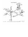
| 8Inbiy
_ — y00l8 paxia (18124) jeutpnyBuo 105)
E / M31IS JE97] ‘ |
240€ © UID 12Ю YIM [99UM SIPUey ajge y
Bes , /
5
(Ian) $5010 101) YoIN|D [BIg YIM 199YAM BIPURH B[qR |
(5) (uonesado Suidde; 10|
YOHMS 919813 |
(oo0jg uoniso y 195 YIM) poy papenpein / A A | SIPUEH PFOH
‘ | 0
«—
©
aC
(биргэ ош 107) j38YM ajpueH po9- 9
009
ACUM YU 1/09 4207 €
Poy pued pidey
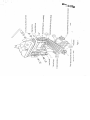
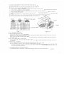
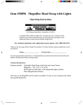
Thank you tor buying the 33686 Milling/Orilling Machina. properly cared for and operated, this machi-
ле сап prova you with years of accurate servico. “lease read this manual carefully before using your
machine,
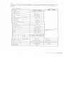
SPECIFICATION
MODEL
ITEM 33686.
ITEM 23686
Drilling capacity
35 31.75mm (1 1/4") 7:24,23mm(7/8")
Face mill capacity
76mm (3")
End mill capacity
20mm (3/4")
Swing 405mm (15-7/8")
Max. distance spindle nose to table 457mm (18")
Spindle taper M.T.3 R-8 7:24
Spindle stroke 130mm (5%)
Diameter of Spindle sleeve 75mm (3")
360
Head swivel
Diameter of column
115mm (4-1/2")
Overall height (w/o stand)
1100mm (43-1/2")
Machine stand height
760mm (30")
1156mm (45 1/2")
Length 1080mm (42-1/2")
Width 1010mm (39-3/4")
Motor 1-1/2hp -- 2HP
Spindle speed), SOM: 100-2080 (4 pola)(75--1685 6pole
(r.p.m.) 60-17 120-2500 (4 pole)(95--2020 pole
—i—— Namen
Forward and backward travel of Table
175mm (7%)
178mm (7)
Right and left traval ef table
500mm (19-3/4")
610mm (24")
Working area of table
730mm“ 210mm (281/4"%X 81/2")
Gross weight
340 kgs (660 lbs)
| 806mmX241 (31 3/4"X9 1/2")
345kgs
Measurament
29.3 Cuft
does
6. PRECAUTION FOR OPERATION
Check all parts for proper condition before operation; if normal safety precautions are noticed carefully,
this machine can provide you withstanding of accurate service.
(1) Before Operation
a) Fill the lubricant.
(a
{b) In order to keep the accurate precision, the table must be free from dust and oil deposits.
(c) Check to see that the tools are correctly set and the workpiece is set firmly.
(d) Be sure the speed is not set too fast.
(
e) Be sure averything is ready before use.
(2) After Operation
(a) Turn off the electric switch.
(b) Turn down the tools.
(c) Clean the machine and coat it with lubricant.
(d) Cover the machine with cloth to keep out the dust.
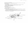
(3) Adjustment of Head
(a) To raise and lower the head, loosen the two heavy duty head lock nuts shown in Fig. 1. Use the
left side head handle to raise and lower the head on its rack and pinion | mechanism. When the de-
sired haight is reached, tighten the bolts to avoid vibration. a >|
(b) Head may be rotated 360* by loosening the same bolts mentioned above. Adjust the head to the
desired angle, then fix the heavy duty head locknuts. You may have to re-tignten lock nuts if the
~ machine is used on a cdntinual basis.
59
Tight Loose //
= A
FT Sam A 4 Lock Bolt With Knob
a o 3
SE у
NU A
$ | —
Spring Base
—— Worm Gear
2— Feed Handle Wheel
Set Position Block |
Figure 2
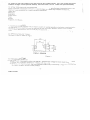
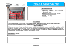
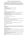
(4) Preparing for Drilling (see fig. 2) (Except addition power feed system).
Turn of the knob make loose the taper body of worm gear and spring base. Then we decide spindle
stroke setting the positive depth stop gauge for drilling blind hole or Free state for pass hole.
(5) Preparing for Milling (see fig. 2) (Except addition power feed system).
(a) Adjust the positive depth stop gauge to highest point position.
(b) Turn tight of the knob be use to taper friction farce coupling the worm gear ane base. Then turning
the handle wheel by micro set the sprindie of work piece machming height.
(c) Lock the rack sleeve at the desired height with fixed bolt.
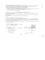
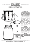
7. ADJUSTING TABLE SLACK AND COMPENSATE FOR WEAR (see fig. 3)
(1) Your machine is equipped with Jib strip adjustment to compensate for wear and excess slack on cr-
oss and longitudinal travel.
(2) Clockwise rotation the jib strip bolt with a big screw for excess slack otherwise a little counter clock-
wise if too tight.
(3) Adjust the jib strip bolt until feel a slingt drag when shifting the table. >
8. CLAMPING, TABLE BASE, AND MACHINE BASE (See Fig. 3)
(1) When milling longitudinal feed, it is advisable to lock the cross feed table travel to insure the accura-
cy of your work. To do this, tighten the small leat screw located on the right side of the table base.
(2) To tighten the longitudinal feed travel of the table for cross feed milling, tighten the two small leaf sc-
rew on the front of the table base. |
(3) Adjustable travel stops are provided on the front of the table for control of longitudinal travel and the
desired milling length.
(OE — Fixed Block
A Jib strip ——
| | — Leaf Screw Leaf Screw
Jio strip Bolt
Jib Strip Bolt
Jib strip
Cross feeding ~~ Longitudinal feeding
Figure 3
«À»
Chas, te same .
O E var SE
— e A , a - E
>
LE Tye
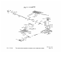
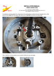
9 SPEED CHANGING AND ADJUST BELT (Step See Fig. 4)
(1) Turn power off.
(2) Open belt cover by releasing side latches step see (a) (b) (c)
(3) Loosen motor mount leaf screw. |
(41 Push motor in order to loosen belts (head side of motor mount is set fixed, two motors ear side with
Motor screw to tighten of loosen of belts.)
(5) Loosen two screws of base for speed change inter pulley that also adjust the location of base tor
speed change inter pulley. |
(6) Select the suitable R.P.M. from speed charts of Fig. 5
steps.
(7) Tighten two screws of base for speed change pulley and the bolt of motor mount lock.
(8) Cover the belt cover with counter step (2) after turn power on;
Then place the belts on the desired pulley
Motor 12s 30MM Spindle shaft
Ze SE —;
CES ere me Atte =
E
10. TO CHANGE TOOLS
(1) Removing Face Mill or Drill Chuck Arbor | |
Loosen the arbor bolt (see fig. 4) at the top of the spindle shaft approximately 2 turns with a wrencn.
Rap the top of the arbor bolt with a mallet.
12SPEEDS BELT 12SPEEDS BELT
50~ | 60 ~ 50~{60~|
100 | 120 4—5 | 640 | 820 | 1—6
160 1200] 3—s 865 [1090| 2—7
190 ¡2501 4—6 [1010|1245| 3—8
{235 1295| 2—5 {1205{1520| 1—7 | chuck Arbor Bolt
305 {4001 3—6 [1500|1820| 2—8
365 1465 | 4—7 1|2080[ 2500| 1—8 3
Figure 5 Figure 4
Alter taper has been broken loose, holding chuck arbor on hand and turn detach the arbor bolt with
the other hand,
(2) To Install Face Mill or Cutter Arbor
Insert cutter and cutter arbor into the taper of spindle. Tighten arbor bolt detach securely, but do not
ove: tighten.
(3) Removing Taper Drills |
(a) Turn down the arbor bolt and insert the taper drill into the spindle shaft.
{b) Turn the spinsle
:Cevo down until the colong hole in the rack sleeve appears. Line up this hole
with the hole in the spindle. Insert Key punch key through holes and strike lightly with a mallet. Th-
is will force the taper drill out.
11. ORDERING REPLACEMENT PARTS
Complete parts list is attached. If parts are needed, contact your local distributor or our factory.
5. =
In order to use mill cutters you will need a R-8 collet holder. You can order this from
Harbor Freight Tools (item# 46004). We also sell a 4 PC. collet set (item# 46002)
12. EXTRA TOOLING AND ACCESSORIES
Each of machine is equipped with a MT = 3 spindle taper or a R-3 spindle taper (examples below ). Co-
ntact your local distributor or a major cutting too! distributor to obtain any of these accessories.
Taper Drills
Reamers
End Mills
Cutter Arbor
Taps
Collets
Adapters and Sleeves
13. TAPPING EQUIPMENT |
This machine can be equipped with an electric switch for tapping operation clockwise or counterclockw-
ise, and the working depth also can be adjusted by the limit switch. (Electric switch will be installed acc-
ording to your requirement, and you must pay the cost only. )
TT 1
/
14. SPECIFICATION OF T-SOLT
The size of T-Solt on table as Fig 6
L 25
16 =
— т
и
— SS
—_ y
7777777 | —
ITEM 33686
Figure 6
15. TROUBLE SHOOTING
(1) No running after switch on:
(a) Main switch interruption while volts irregular - Adjust input voltage and draw back the main switch
(b) Break down of fuse in switch box - Replace with new cae
(ce) In casa <í tco much current, the overload relay jumps away automatically - Press the overload rel-
ay, and it will return to the correct position.
REV 07/06
Ar A
(2) Motor Overheat and No Power:
(a) Overload - Decrease the load of feed.
(5) Lower voltage - Adjust to accurate voltage.
(c) Spoiled contact point of magnetic switch - Replace with new one.
(d) Breakdown of overload relay - Connect it or replace with new one.
(e) Motor is poor - Replace with new one.
(f) Break down of tuse or poor contact with vrire (it is easily to spoil motor while shot circuited: Switc-
h off power source at once and replace fuse with new one.
(а) The tension of pulley V-belt too tight - Adjust for proper tension of V-Belt.
“(h) If this machine with the tapping attachment, there is an aid plum screw fix on the motor mount in
order to avoid the motor pulleys shake while turning.
(3) The temperature cf spindle bearing is too hot:
(a) Grease is insufficiont - Fill the grease.
(b) The spindie bearing is fixed too tight - Turning with no speed and feel the tightness with hand.
(c) Turning with high speed for a long time - Turn it to lightly cutting.
(4) Lack of power with main spindle revolving: |
(a) The tension of V-belt too ioose - Adjust for proper tension of V-belt. >
(b) Motor has burned out - Change a new motor. Ш
(c) Fuse has burned out - Replace with new one.
(5) Table travel has not balanced:
(a) The gap of spindle taper too wide - Adjust bolt in proper.
(b) Loosening of leaf bolt - Turn and fas.zn in place.
(c) Feed too deep - Decrease depth of feed.
[ O ER
(6) Shake of spindle and roughness of working sunace has taken place during pertornance:
(a) The gap of spindle bearing too wide - Adjust the gap in proper or repiase bearing with new one.
(b) Spindle loosening up and down - Make two of inner bearing covers on the top tight each other,
Do not overtighten two inner bearing covers with the taper bearing; it is OKas long as no gap
between them. |
° (с) The gap of taper sliding plate too Wide - Adjust the tension of bolt in proper
(d) Loosening of chuck - Fasten chuck. |
(e) Cutter is dull - Resharpen it.
(f) Workpiece has not hold firmly - Bé sure to tighten workpiece.
(7) Micro feed does not work smoothly:
{a) Loosening of clutch - Be sure to tighten it.
(b) Worm and worm shaft has worn out - Replace with new one.
(c) Loosening of handwheel fixed screw - Be sure to tighten it.
(B) Without accuracy in performance:
(a) Imbalance of heavy workpiece - Must be considerate of the principle of balancewhile holding
workpiece. |
(b) Often use of hammer to strize workpiece - Forbidden to use hammer to strike workpiece.
(c) Unaccurate horizontal table - Check and maintain table for keeping accurate horizontal after a pe-
riod of use.
16. MAINTAINIING
That's easier to keep machine in good condition or best performance by means of maintaining if at any
time than remedy if after it is out of order
(1) Daily Maintenance (by operator)
(a) Fill the lubricant before starting machine everyday.
(b) If the temperature of spindle caused overheating or strange noise, stop machine immediately to
check it for keeping accurate perfcrmance.
(c) Keep work area clean; release vise, cutter, workpiece from table: switch off power source: take
chip or dust away from machine and follow instructions lubricanting or coating rust-proof cit be-
tore leaving. |
(2) Weekly Maintenance
(a) Clean and coat the cross leading sorew with oil.
(b) Check to see if sliding surface and turning parts lack of lubricant. If the libricant is Msufficant, fill it.
(3) Monthly Maintenance ВЕ
(a) Adjust the accurate gap of slide both on cross and longitudinal leed.
(b) Lubricate bearing, worm, and worm shaft to avoid wear. | ие о)
(4) Yearly Maintenance
(a) Adjust table to horizontal position for maintenance of accuracy.
(b) Check electric cord, plugs, switches at least once a year to avoid loosening or wearing.
SKU 33686
1 Chuck Arbor Bolt
2 ELT Pulley Lock Nut
3 Spindle Pulley
4 Belt bottom Cover
5 Dust Cover
6 Spindie Taper Sleeve
7 Ball Bearing( + 6009 ZZ)
8 Bearing Spacer
9 C— Retainer Ring
10 C ~ Retainer Ring
11 Head Body
12 Rubber Flange
13 Feed Base
14 Lock Nuts
15 Taper Roller Bearing(302061)
16 Rack Sleeve
17 Spindle Shaft
18 Taper Roller Bearing(E3020671)
19 Bearing Cap
20 Cutter Arbor
21 Chuck Arbor
22 Grip
23 Retainer Ring
24 Handie Rod
25 Fixed Tight Collar
26 Fixed Tight Collar( Thread)
27 Screw Key
28 Lift Knob
29 Handie Rod
30 Knob
31 Micro Adjusting indicator
32 Worm Cover
33 Ball Bearing(6202Z)
34 Worm Shaft
35 Lock Handle
36 Leaf Screw
37 Head Body Fix Bolt
38 Graduated Rod
39 Graduated Dial
40 Switch
41 Name Plate
42 Worm Shaft
43 Angular Gear
Parts List
pa > Y O) 4 > ao A LJ a A A RI 5 BD) 3 74 = 1 RJ A A a ed
Ft pia pd pd pr pd AD ei а A
44 Shaft
45 Compression Spring
46 vibration ~ Proof Pole
47 Motor Mount
48 Motor
- 49 Punch Key
50 Belt Cover
51 Motor Pulley
52 V- Belt(B813)
53 Ball Bearing(62042)
54 Inter Pulley
55 V- Belt(B1016 — 1041)
56 Inter Pulley Shaft
57 Speed Change Inter Pulley Base
98 Clip Plate
39 Hubber Collar
60 Screw With Plumb Knob
61 Cutter
62 Set Distance Nut
63 Set Position Block
64 Lock Nut
6S Support Base
66 Handle
67 Front Cover Plate
68 Push Switch Protection Plece
69 PU- Down with stand
70 Limit Plate
71 Spring Cover
72 Spring
73 Spring Base
74 Pinion Shaft
75 Worm Gear
76 Feed Box
77 Buffer Spring
78 Spring base
79 Terminal
80 Hexagon Head Bolt
81 Washer
82 Cross — Recess Round Head Screw
83 Hexagon Head Bolt
84 Hexagon Nut
85 Capacitor Housing
Pri 4 en pb ей ed pea NI Jed ped pd pd pd pt A 8 fd
420 =» (5) pet pd pt pd ed = PB 8 ped ed я Beh pe A
>
as о
REV 06/02; 11/03
For technical questions, please call 1-800-444-3353.
Page 9
Parts List (continued)
85 Cone Pin
86 LockWasher
87 Cross - Recess Round Head Screw
88 Spring Pin —
89 Hexagon Nut
90 Key
91 Hexagon Socket Head Screw
92 Hexagon Socket Headless Screw
93 Hexagon Socket Headless Screw
94 Hexagon Socket Head Screw
95 C - Retainer Ring
96 Hexagon Nut
97 Washer
98 Cross - Recess Round Head Screw
99 Hexagon Socket Headless Screw
100 O - Retainer Ring
101 Hexagon Socket Head Screw
102 Hexagon Head Screw
103 Hexagon Head Screw
104 Hexagon Nut
105 Key
106 Hexagon Head Bolt
107 Washer
108 Outline Bush
109 Cross - Recess Round Head Screw
110 Cross - Recess Round Head Screw
111 Cross - Recess Round Head Screw
112 Washer
113 . Cross - Recess Round Head Screw
114 Lock Bolt with Knob
115 Feed Handle Wheel
116 Table Handle Wheel
117 Dial Handle
118 Thrust Bearing (S1103)
119 Square Flange
120 Feeding Plate Screw
SKU 33686
121
122
123
124
125
126
127
128
129
130
131
132
133
134
135
136
137
138
139
140
141
142
143
144
145
146
147
148
149
150
151
152
153
154
155
Body
Gib Strip
Vertical Shaft
Shaft Bottom
Rack
Shaft Cover
Jib Strip Bolt
Leaf Screw
Movable Fixed Block
Table Down Nut
Center Base
Anti-dust Press Plate
Anti-dust Plate
Anti-dust Press Plate
Left Flange
Table Upper Nut
Table Screw
Right Flange
Table Gib Strip
Table
Fixed Block
Movable Fixed Ring
Hexagon Head Bolt (Same3-131)
Hexagon Socket Head Screw
Hexagon (Same3-145)
Cone Pin
Indicated Zero With Screw
Locking Screw
Hexagon Head Bolt
SpringWasher
Hexagon Socket Head Screw
Hexagon Socket Head Screw
Hexagon Socket Head Screw
Hexagon Socket Head Screw
Adjusting Plate
CON BD DD DAL BAN a
ГО Го ГО — Г + +
REV 06/02; 08/05; 10/05
For technical questions, please call 1-800-444-3353.
Page 10
Parts Diagram
¢ 9
28 40114 «
NE 24 10
42
“то | “©.
10208)
JH? 70
“1 ° SON
5-77 $ Sasol PEE
2-86 25 Es
<-5 93-4 pro 4
29131
i
&- 61
REV 06/02; 11/03; 08/05; 10/05
SKU 33686 For technical questions, please call 1-800-444-3353. Page 11
Parts Diagram
A17 5-148
El”
\ d se gls
116 AN |
EX
1367
7
138
130
14502), OS
un 121
1
14512) --
19
117. =.
> < 118 “дв
“48
116
REV 06/02; 10/05
SKU 33686 For technical questions, please call 1-800-444-3353. Page 12
Pa
COUCT b +
bs:t&b
18°d
28FM P1
11 2202 O1
RUG.
FROM
,
%
+
F
ME
pore|nsux ay pynoys JT ‘GLIA 8103 14
PO -[11 JO 3174 97 TA UTA 1990009 ‘ |
| A 1 uo A
| : | Pp 'a077 3UTUINI GTI
ya e He
5 Ш Toto yO of aa 1Tp BUY
o3ueys M9 (2 )onyg O 10 (£) 6nIq pus (e) eJITUYA su ue “y x
2100-11} JO OMITA 294098 (£) 'eT09-9TQNOP JO 9X14 IDACI A
ау] А i
(€) vasad х
Pm (e) 99 TA :
(c)antq | (t)u3a1s —
лелоб (ema (ante .
(@yusotay (2) roxy —
-
[
}
"de
de
.
+ fes
+
SE о” (£) 19913 —
(6) 93 уЧ& ——
a. (4) 2719 —
1 (£) 7 —
RO (Z) UMOIG =
(ANTE
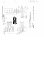
of 101 Ley) ln IHL 29H)
NTH HMITINIO 7 HNTTIIA mE AS Yo WWiVIC LNTUITN
—
10300 sors aX 1704
| N |