1
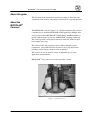
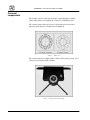
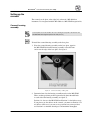
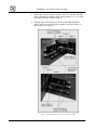
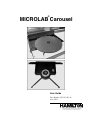
®
MICROLAB Carousel
User Guide
Part Number 8534-01 (Rev. A)
June 2003
MICROLAB® Carousel User Guide (June 2003)
Contents
About this guide . . . . . . . . . . . . . . . . . . . . . . . . . . . . . . . . . . . . . . . 1
About the MICROLAB® Carousel . . . . . . . . . . . . . . . . . . . . . . . . . . 1
Safety precautions . . . . . . . . . . . . . . . . . . . . . . . . . . . . . . . . . . . . . 2
FCC compliance . . . . . . . . . . . . . . . . . . . . . . . . . . . . . . . . . . . . . . . 3
Carousel components . . . . . . . . . . . . . . . . . . . . . . . . . . . . . . . . . . . 4
Setting up the carousel . . . . . . . . . . . . . . . . . . . . . . . . . . . . . . . . . . 5
Carousel housing assembly . . . . . . . . . . . . . . . . . . . . . . . . . . . 5
Index bracket platter kit . . . . . . . . . . . . . . . . . . . . . . . . . . . . . . 7
DIP switch setting . . . . . . . . . . . . . . . . . . . . . . . . . . . . . . . . . . . 8
Connecting cables . . . . . . . . . . . . . . . . . . . . . . . . . . . . . . . . . . 10
Carousel platter . . . . . . . . . . . . . . . . . . . . . . . . . . . . . . . . . . . . 11
Operation . . . . . . . . . . . . . . . . . . . . . . . . . . . . . . . . . . . . . . . . . . . . 13
Installing the software . . . . . . . . . . . . . . . . . . . . . . . . . . . . . . . 13
Calibration . . . . . . . . . . . . . . . . . . . . . . . . . . . . . . . . . . . . . . . . 15
Carousel service software . . . . . . . . . . . . . . . . . . . . . . . . . . . . 17
Writing a method . . . . . . . . . . . . . . . . . . . . . . . . . . . . . . . . . . . 18
Carousel commands . . . . . . . . . . . . . . . . . . . . . . . . . . . . . . . . 20
Using the serial interface . . . . . . . . . . . . . . . . . . . . . . . . . . . . . 21
Installing portrait stackers and shelves . . . . . . . . . . . . . . . . . . 22
Installing landscape stackers . . . . . . . . . . . . . . . . . . . . . . . . . . 22
Maintenance . . . . . . . . . . . . . . . . . . . . . . . . . . . . . . . . . . . . . . . . . . 24
General . . . . . . . . . . . . . . . . . . . . . . . . . . . . . . . . . . . . . . . . . . 24
Troubleshooting . . . . . . . . . . . . . . . . . . . . . . . . . . . . . . . . . . . . . . . 25
Specifications . . . . . . . . . . . . . . . . . . . . . . . . . . . . . . . . . . . . . . . . . 26
Parts and accessories . . . . . . . . . . . . . . . . . . . . . . . . . . . . . . . . . . 28
Contacting Hamilton Company . . . . . . . . . . . . . . . . . . . . . . . . . . . . 29
In the United States and Canada . . . . . . . . . . . . . . . . . . . . . . . 29
Outside the U.S. and Canada . . . . . . . . . . . . . . . . . . . . . . . . . 29
In Switzerland . . . . . . . . . . . . . . . . . . . . . . . . . . . . . . . . . . . . . . 29
ii
Contents
MICROLAB® Carousel User Guide (June 2003)
About this guide
This user guide is for instructional and reference purposes. It describes the
components of the carousel and provides instructions for set up and operation.
About the
MICROLAB®
Carousel
The MICROLAB® Carousel (figure 1) is a modular component. The carousel
is intended for use with the MICROLAB® SWAP application. Multiple units
can be placed around a MICROLAB® SWAP (Swivel Arm Platehandler) to
provide additional plate capacity for a MICROLAB® pipetting workstation.
The carousel provides an integrated solution for increased volume for plate
based sample processing.
The carousel works with two platter sizes to address multiple capacity
requirements. Various SWAP stacks and shelves can sit atop the carousel,
providing storage of plates and plate sized consumables.
The carousel can also be used for storage of disposable tips, for some
applications and instruments.
MICROLAB® Vector software is used to control the carousel.
Figure 1: Carousel accessory
1
MICROLAB® Carousel User Guide (June 2003)
Safety precautions
There are four symbols used in this guide.
The “Warning” symbol contains information that must be followed to prevent personal injury to those
operating the equipment.
The “Important” symbol contains information or instructions that must be followed to prevent damage
to equipment or loss of data.
The “Note” symbol provides information useful for improving system performance, increasing your
understanding of the system, or directing you to supplemental information.
The “Procedure” symbol is followed by a set of installation or operational steps.
2
MICROLAB® Carousel User Guide (June 2003)
FCC compliance
The MICROLAB® Carousel complies with the limits for Class B digital
devices by the Federal Communications Commission (FCC). This compliance
provides reasonable protection against harmful radio communication
interference during instrument installation and operation.
The MICROLAB® Carousel generates, uses, and can radiate radio frequency
energy. Hamilton Company cannot guarantee the MICROLAB® Carousel
against radio or television communication interference. However, if you use
the instrument as directed, you can limit potential interference.
If the MICROLAB® Carousel causes any radio or television interference, we
suggest that you:
•
Turn the MICROLAB® Carousel off and on to determine whether it is
generating the interference.
•
Reorient or relocate the receiving antenna.
•
Increase the separation between the MICROLAB® Carousel equipment
and the receiver.
•
Connect the equipment to an outlet on a different circuit than the receiver.
•
Contact the instrument dealer or an experienced radio/TV technician for
help.
3
MICROLAB® Carousel User Guide (June 2003)
Carousel
components
The carousel consists of the carousel platter, carousel housing assembly,
cables, and hardware for attaching the carousel to a SWAP base plate.
The carousel platter comes in two sizes, 10 position universal and an 8
position portrait (figure 2). Each position is numbered.
Figure 2:
Platter sizes
The carousel housing assembly (figure 3) houses belts, pulleys, motor, and a
carousel access interface PCB assembly.
Figure 3:
4
Carousel housing assembly
MICROLAB® Carousel User Guide (June 2003)
Setting up the
carousel
The carousel can be place at the right, left, or front of a ML 4000 base
instrument. It is integrated with the ML 4000 via a ML SWAP integration kit.
Carousel housing
assembly
If the base plate has not been installed, refer to the “Attaching the base plate to the ML 4000” of the
ML SWAP/4000 Series Integrated System User Guide (7157-01).
To install the carousel housing assembly to the base plate:
1. Place the carousel housing assembly on the base plate, opposite
the ML SWAP. Position the housing assembly so that the front
end is near the edge of the base plate. See figure 4.
Figure 4: Carousel housing on base plate
2. Determine how close the housing assembly must be to the ML SWAP.
There are three positions possible represented by three threaded holes
in each side of the housing assembly (see figure 5).
Position 1 is closest to the ML SWAP, and Position 3 is the farthest away.
If you plan to use the shelves on the carousel, you must use Position 3. If
no shelves will be used, you can use any position, but you may wish to
use Position 1 to minimize bench space and maximize throughput.
5
MICROLAB® Carousel User Guide (June 2003)
3. Secure the carousel base plate brackets (7918-01) to the left and right
sides of the housing assembly, in the desired position (1, 2, or 3), with
the washer and screw shown in figure 5.
4. Align the holes of the brackets to the holes in the ML SWAP base
plate. Using the screws and washers supplied, secure the brackets to
the base plates (see figure 5).
Figure 5:
6
Right and left sides of carousel housing assembly
MICROLAB® Carousel User Guide (June 2003)
Index bracket platter
kit
The carousel comes with an index bracket kit (8488-01 or -02). The index
bracket is used during calibration.
To install the index bracket to the carousel housing assembly:
1. Mount the index bracket (8322-01 or -02) to the right side of the
carousel housing assembly, using the two screws (8365-01)
supplied from the index bracket kit. See figure 6.
2. Mount the index pointer (8383-01 or 8527-01) on to the index
bracket, using two screws (8375-01) supplied from the index
bracket kit. See figure 6.
Figure 6:
8/10 station carousel index bracket components
7
MICROLAB® Carousel User Guide (June 2003)
DIP switch setting
Before connecting the carousel to the PC, the communication settings must be
checked and, if necessary, adjusted.
To set the DIP switch settings of the carousel:
1. Locate the DIP switch on the left side of the carousel housing
assembly (figure 7).
2. Check and, if necessary, set the switch as needed (figure 8). Table 1
lists the selection options for the switch. Switches 1 through 3
define the platter size. All other settings beside those shown are
undefined.
Switches 4 through 6 define which carousel (up to 8) will be controlled by
the PC.
Switches 7 and 8 should be off for most applications.
Use a screwdriver or a similar tool to adjust the DIP switch settings. A pencil is not advised, as the
graphite can affect the operation of the carousel.
Figure 7:
8
DIP switch location
MICROLAB® Carousel User Guide (June 2003)
Figure 8:
DIP switch (Set for 10 position universal platter)
Table 1.
DIP switch selection
PLATTER SELECT
SW1-1
SW1-2
SW1-3
DESCRIPTION
OFF
OFF
OFF
8 POSITION PORTRAIT (DEFAULT)
ON
ON
OFF
10 POSITION UNIVERSAL
UNIT IDENTIFICATION
SW1-4
SW1-5
SW1-6
DESCRIPTION
OFF
OFF
OFF
UNIT 1 (DEFAULT)
ON
OFF
OFF
UNIT 2
OFF
ON
OFF
UNIT 3
ON
ON
OFF
UNIT 4
OFF
OFF
ON
UNIT 5
ON
OFF
ON
UNIT 6
OFF
ON
ON
UNIT 7
ON
ON
ON
UNIT 8
SPARE
SW1-7
DESCRIPTION
OFF
(DEFAULT)
ON
TBD
FORCED DOWNLOAD
SW1-8
DESCRIPTION
OFF
(DEFAULT)
ON
FORCED DOWNLOAD
9
MICROLAB® Carousel User Guide (June 2003)
Connecting cables
To install the carousel power and communication cables:
1. Connect the USB cable (4427-02) to the USB port of the carousel
housing assembly (refer to figure 7).
2. Connect the other end of the USB cable to one of the USB ports of
the computer that will be used to operate the carousel.
3. Plug the power cord into the power outlet in the side of the housing
assembly. Orient the plug as shown in figure 9. Plug the power
adapter into a wall outlet.
The carousel can be controlled via RS-232 instead of USB. If Vector software will be used to control
the carousel, then USB is preferred.
Figure 9:
10
Plug orientation
MICROLAB® Carousel User Guide (June 2003)
Carousel platter
To install the carousel platter:
1. Place the carousel platter on top of the carousel housing
assembly. See figure 10. Align the three holes in the platter with
the threaded holes in the housing assembly.
2. Attach the carousel platter to the carousel housing assembly using three
screws (8372-01), supplied from the index bracket kit, and a 3/32” hex
wrench.
Figure 10:
Carousel platter
3. Use an adjustable wrench to adjust the nuts on all the mounting feet
(7419-01), so the carousel platter is level. See figure 11.
Do not rotate the carousel platter by hand.
11
MICROLAB® Carousel User Guide (June 2003)
Figure 11:
12
Mounting feet locations
MICROLAB® Carousel User Guide (June 2003)
Operation
Installing the software
After your MICROLAB® Carousel hardware is installed, you can install the
Hamilton MICROLAB® Carousel Software.
Your MICROLAB® Carousel software comes with an installation wizard that
guides you through the installation as it copies the program files to your
computer.
Before you begin the installation, make sure that you have closed any open
applications on your PC. Carousel software requires Windows 2000 (with
service pack 2 or higher) or Windows XP Professional, and 128 MB RAM
(minimum).
If installing SWAP software also, and SWAP version is 2.0 or less, SWAP
software must be installed first.
To install MICROLAB® Carousel software:
1. Place the CD labeled “Hamilton MICROLAB® Carousel Software”
into the CD drive on your PC.
2. The install program should run automatically. If it does not, select
Start > Run > (the CD-ROM drive identifier on your PC) \
Setup.exe. Click the OK button when the prompt appears.
The InstallShield Wizard starts when the Welcome to the InstallShield
Wizard for Carousel window appears (figure 12).
Figure 12: Welcome window
13
MICROLAB® Carousel User Guide (June 2003)
3. Click Next >. A Question window appears (figure 13) asking whether
desks icons are desired.
Figure 13:
Question window
4. Click No. The Instrument Identification window appears. Click Yes
only if no other Vector components or instruments will be installed.
5. Click Finish. A Setup Status window appears, and then a Laboratory
Name window appears.
6. Type the name of your lab and click Next.
After MICROLAB® Carousel software has completed its installation, the
InstallShield Wizard Complete window appears.
7. Click Finish to exit from MICROLAB® Carousel Setup window.
14
MICROLAB® Carousel User Guide (June 2003)
Calibration
Calibration sets an offset angle from the default initialization position.
To calibrate the carousel:
Do not rotate the carousel platter by hand.
1. Select Start > Programs > Hamilton > Carousel > Service
Software from the Windows desktop. The Service Software
window appears.
2. Select Communication > Connect. A Select Instrument window
appears.
3. Select the Carousel and click OK. The File transfer icon (arrows) on
the tool bar should turn from gray to blue if communications are
established.
4. Click on Instruments Carousel > Calibration. The carousel will
initialize, and a Calibrate Carousel window will appear (figure 14).
Figure 14: Calibrate Carousel window
5. Use the left and right arrow keys to rotate the carousel. Each
keystroke will move the platter the number of degrees shown in the
window (refer to figure 14). Change that resolution as needed.
Move the platter until position #1 aligns with the intended plate pickup
position. In most cases this is 90o counter-clockwise from the index
pointer (figure 15).
15
MICROLAB® Carousel User Guide (June 2003)
For the 8-position platter, align the #7 position line with the center line of
the index pointer.
For the 10-position platter, align the #9 position line with the center line
of the index pointer. Then type 18 into the keyboard resolution field, and
hit the right-arrow key once.
6. Click OK. A window appears asking you to “Reset instrument
now”. Unplug the carousel, wait 5 seconds, and plug the carousel
back in. Wait another 5 seconds, and click OK.
Figure 15:
16
Calibration alignment
MICROLAB® Carousel User Guide (June 2003)
Carousel service
software
In addition to the Service Software for the ML 4000 series, you can also
access Carousel Service Software. There are three utilities that can be used to
troubleshoot the carousel, but which are generally not needed.
To use the Carousel Service Software:
1. Select Start > Programs > Hamilton > Carousel > Service
Software from the Windows desktop. The Service Software
window appears.
2. Select Communication > Connect. A Select Instrument window appears.
3. Select the Carousel and click OK. The File transfer icon (arrows) on
the tool bar should turn from gray to blue if communications are
established.
4. Click on Utilities > Analyze log. This brings up the log viewer window.
You can use this to open log files for interpretation. Most often, the log
files are use by Hamilton company to analyze hardware problems.
5. Click File > Exit to return to the Service Software window.
6. Click on Utilities > File Transfer. The File Transfer Utility window
appears. This utility is used to download firmware and retrieve log
files from the carousel. You must know the checksum of the new
firmware to use this feature. Contact Hamilton Company for more
information.
7. Click the Exit button to return to the Service Software window.
8. Click on Utilities > Version Numbers. A version numbers window
appears. Use this utility to verify that the carousel firmware is current.
9. Click OK to return to the Service Software window.
17
MICROLAB® Carousel User Guide (June 2003)
Writing a method
To access the Hamilton method editor:
1. Double-click the MICROLAB® Method Editor icon on your
desktop. The Hamilton Method Editor window appears.
2.
Select File > New. Assign a name to your new method, and click
Save.
3. The screen will show a cluster of General command icons on the left
and a blank method on the right (figures 16). No instrument specific
commands are immediately available. You need to select an
instrument from the Hamilton Method Editor window.
Figure 16:
Hamilton Method Editor - Carousel.med window
4. Select Method > Instruments from the Hamilton Method Editor
window. The Instruments window appears (figure 17).
5. Click on the check box for the Carousel and click OK. The
Hamilton Method Editor appears (figure 18), but now it has a set of
instrument commands for the carousel.
6. Click on the instrument command bar (Carousel). The command set
for that instrument will appear (figure 19).
Now it is possible to write a complete method by dragging commands to the
white blocks in the method window.
Refer to the MICROLAB Vector software user manual for more information regarding the software in
general.
18
MICROLAB® Carousel User Guide (June 2003)
Figure 17: Instruments window
Figure 18:
Figure 19:
Hamilton Method Editor with Carousel command bar
Method Editor with instrument icons command set
19
MICROLAB® Carousel User Guide (June 2003)
Carousel commands
There are two commands associated with the carousel.
•
Initialize
Use this command to initialize the carousel.
•
Move To Position
This command rotates the carousel around to the position set in the
parameter dialog box (figure 20). The carousel will rotate in the shortest
direction.
Figure 20:
20
Move to Position Parameters window
MICROLAB® Carousel User Guide (June 2003)
Using the serial
interface
The carousel can be run via the serial interface rather than the USB interface.
The carousel can then be controlled by the general serial port commands in
Vector, by other software utilities such as Hyperterminal, or by customerspecific software interfaces.
A “straight-through” cable, such as Hamilton part number 36786, is required.
Table 2 shows some examples of carousel commands that can be used in
serial mode. For the Move command, “w60” asks for the position to move to,
“3” sets the position to position 3, and “x61” moves the carousel to the set
position.
Command type
Send
Receive
Initialize
0x60<CR>
0r4<CR><LF>
Move
0w60, 3x61<CR>
0r4<CR><LF>
Query position
0q61<CR>
0r,3<CR><LF>
Table 2.
Example commands for the serial interface.
Notes:
•
For invalid commands, an error code is returned. Refer to table 3 on
page 25 (“Troubleshooting”).
•
The positions are hexadecimal (for example, position 10 is 'a').
•
The maximum number of positions is set by the DIP switch on the
housing assembly. Refer to table 1 on page 9.
•
If a move command is sent before the instrument is initialized, the
instrument will first initialize, and then the carousel will move to the
designated position.
•
The instrument must be calibrated via USB and service software. See
“Calibration” on page 15.
•
For more information, please contact Hamilton Company.
21
MICROLAB® Carousel User Guide (June 2003)
Installing portrait
stackers and shelves
To install a stacker or shelf:
1. Line up the hole in the base and the notched corners of the stacker
or shelf with a set of three guide pins on the carousel.
2. Rest the stacker or shelf on the platter (figures 21).
Figure 21:
Portrait stackers and shelf
Installing landscape
stackers
To install a landscape stacker on the 10-position carousel:
1. Line up the middle of the landscape stacker with numbered
position line on the carousel (see figure 22).
2. Rest the stacker on the platter (figure 23).
22
MICROLAB® Carousel User Guide (June 2003)
Figure 22:
Location of numbered position line
Figure 23:
Landscape stackers
23
MICROLAB® Carousel User Guide (June 2003)
Maintenance
Maintenance of the carousel will assure its long-term operation.
General
24
•
Wipe up spills as soon as possible. Clean according to the applicable
MSDS (Material Safety Data Sheets) or laboratory SOP (Standard
Operating Procedures).
•
No field lubrication is required.
•
Motor, belts, and electronics are serviced by Hamilton Company
Technical Service personnel.
MICROLAB® Carousel User Guide (June 2003)
Troubleshooting
In the event of an error during run time, click on the Help button (if
available). The message should provide some clues to the cause of the error
and a possible remedy. If not, try to reproduce the error, record the error code
and message, and notify Hamilton Company Technical Service. See
“Contacting Hamilton Company” section on page 29. In addition, table 3
lists the most common error conditions for the carousel and the associated
corrective actions.
Table 3. Common error conditions
Error code
Possible cause
Corrective action
Ox5E 8001
Unable to initialize
Contact Hamilton Service
Ox5E 8002
Unable to initialize
Contact Hamilton Service
Ox5E 8003
Motion not detected
Bad sensor; contact
Hamilton Service
Ox5E 8004
Motor stalled
Remove obstacles. Avoid
moving platter by hand
during motion.
25
MICROLAB® Carousel User Guide (June 2003)
Specifications
Carousel
Parameter
Specification
Power requirements
24V @ 2 Amps maximum
Power Supply
100 - 200V~, 50-60Hz 1A
Communication type
RS-232 or USB
Operating
Temperature
Relative Humidity
5o to 40oC (41o to 104oF)
10% to 90% non-condensing
Storage
Temperature
Relative Humidity
-20o to 70oC (-4o to 158oF)
10% to 90% non-condensing
Speed
Maximum 10 seconds to rotate to any
position (Typical 4 seconds).
Altitude (Maximum)
2000 m (6562 ft.)
CSA Certification
Installation category
Pollution degree
II
2
CE Approval
Safety
EMC
IEC 1010-1
IEC 1010-1/A1
IEC 1010-1/A2
(1990)
(1992)
(1995)
EN 61326-1
(1997)
Carousel housing assembly
Dimensions:
Length
Width
Height
14.63" (371.6mm)
20.50" (520.7mm)
3.60" (91.4mm)
Weight
11.3 lb. (5.1 kg)
Carousel 8 position platter
Dimensions:
Diameter
Thickness
20.717" (526.2mm)
0.313" (8mm)
Weight
10 lb. (4.5kg)
Carousel 10 position platter
Dimensions:
Diameter
Thickness
25.5" (647.7mm)
0.375" (9.5mm)
Weight
17.7 lb. (7.9kg)
Indoor Operation and Use Only
26
MICROLAB® Carousel User Guide (June 2003)
Figure 24: Overhang distance of platters from SWAP
base plate (refer to figure 5 for bracket positions)
27
MICROLAB® Carousel User Guide (June 2003)
Parts and
accessories
Cable
Part Number
Description
4833-01
Power adapter
6541005
Power cord
36786
RS-232 cable
4427-02
USB cable, 3m
Shelves and stackers
Part Number
Description
180052
Shelf, Portrait
6913-01
Stacker, Landscape
180050
Stacker, Portrait
Software
Part Number
Description
9266-01
CD, MICROLAB® Carousel Software
4060-01
CD, MICROLAB® Vector Software
Manuals
Part Number
28
Description
8534-01
MICROLAB® Carousel User Guide
7157-01
MICROLAB® SWAP/4000 Series Integrated System User Guide
5606-01
MICROLAB® Vector Software User Manual
MICROLAB® Carousel User Guide (June 2003)
Contacting Hamilton Company
In the United States
and Canada
Hamilton Company • 4970 Energy Way • Reno, Nevada 89502
Phone
Customer Service:
Technical Service:
Instrument Service:
800.648.5950 (7 a.m. to 5 p.m. PT)
800.648.5950 (8 a.m. to 4 p.m. PT)
800.527.5269 (24 hours)
Fax:
775.856.7259
E-mail:
[email protected]
[email protected]
[email protected]
URL
www.hamiltoncompany.com
Phone:
775.858.3000
Fax:
775.856.7259
E-mail:
[email protected]
[email protected] or
[email protected]
URL:
www.hamiltoncompany.com
Outside the U.S. and
Canada
In Switzerland
Hamilton Bonaduz AG • Ch-7402 • P.O. Box 26 • Bonaduz, Switzerland
Phone:
41.81.660.60.60
Fax:
41.81.660.60.70
E-mail:
[email protected]
[email protected]
URL:
www.hamiltoncompany.com
29
MICROLAB® Carousel User Guide (June 2003)
30
MICROLAB® Carousel
User Guide
Part No. 8534-01 (Rev. A)