1
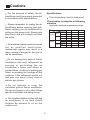
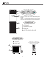
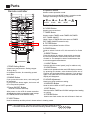
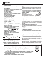
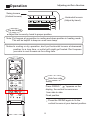
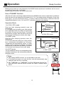
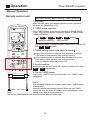
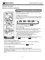
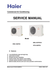
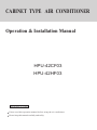
CABINET TYPE AIR CONDITIONER
Operation & Installation Manual
HPU-42CF03
HPU-42HF03
No.0010576728A
Please read this operation manual before using the air conditioner.
Please keep this manual carefully and safely.
Content
Operation
Cautions
1-2
Parts
3-5
Operation
6-11
Operation hints
12
Energy saving
13
Maintenance
Trouble shooting
When problems occur
14-15
16
17-18
Indoor & outdoor unit connection
19
Tools necessary
20
Installation procedures
Others
21-26
27
Cautions
Disposal of the old air conditioner
All these valuable materials may be taken
to a waste collecting center and used again
after adequate recycling.
Before disposing an old air conditioner
that goes out of use, please make sure
it's inoperative and safe. Unplug the air
conditioner in order to avoid the risk of
child entrapment.
Consult your local authorities for the name
and address of the waste materials
collecting centers and waste paper
disposal services nearest to your house.
It must be noticed that air conditioner
system contains refrigerants, which
require specialized waste disposal. The
valuable materials contained in a air
conditioner can be recycled. Contact
your local waste disposal center for
proper disposal of an old air conditioner
and contact your local authority or your
dealer if you have any question. Please
ensure that the pipework of your air
conditioner does not get damaged prior
to being picked up by the relevant
waste disposal center, and contribute
to environmental awareness by
insisting on an appropriate, antipollution method of disposal.
Safety Instructions and Warnings
Before starting the air conditioner, read
the information given in the User's Guide
carefully. The User's Guide contains very
important observations relating to the
assembly, operation and maintenance of
the air conditioner.
The manufacturer does not accept
responsibility for any damages that may
arise due to non-observation of the
following instruction.
Damaged air conditioners are not to
be put into operation. In case of doubt,
consult your supplier.
Disposal of the packaging of your
new air conditioner
Use of the air conditioner is to be
carried out in strict compliance with the
relative instructions set forth in the User's
Guide.
All the packaging materials employed
in the package of your new air
conditioner may be disposed without
any danger to the environment.
Installation shall be done by professional
people, don't install unit by yourself.
The cardboard box may be broken or
cut into smaller pieces and given to a
waste paper disposal service. The
wrapping bag made of polyethylene
and the polyethylene foam pads
contain no fluorochloric hydrocarbon.
1
Cautions
Specifications
For the purpose of safety, the air
conditioner must be properly grounded
in accordance with specifications.
The refrigerating circuit is leak-proof.
The machine is adaptive in following
situation
Always remember to unplug the air
conditioner before opening inlet grill.
Never unplug your air conditioner by
pulling on the power cord. Always grip
plug firmly and pull straight out from
the outlet.
Applicable ambient temperature range:
Rated Maximum Minimum
32
18
DB C 27
Indoor
23
14
WB C 19
Cooling
43
10
outdoor DB C 35
WB C 24
26
6
27
15
Indoor DB C 20
Heating
--WB C 14.5
7
24
-7
DB
C
outdoor
18
-WB C 6
All electrical repairs must be carried
out by qualified electricians.
Inadequate repairs may result in a
major source of danger for the user of
the air conditoiner.
Do not damage any parts of the air
conditioner that carry refrigerant by
piercing or perforating the air
conditioner's tubes with sharp or
pointed items, crushing or twisting any
tubes, or scraping the coatings off the
surfaces. If the refrigerant spurts out
and gets into eyes, it may result in
serious eye injuries.
Do not obstruct or cover the
ventilation grille of the air conditioner.
Do not put fingers or any other things
into the inlet/outlet and swing louver.
Do not allow children to play with the
air conditioner. In no case should
children be allowed to sit on the
outdoor unit.
2
Parts
1
ON/OFF
POWER
ON/OFF
POWER
RUN
TIMER
HEATER
RUN
TIMER
HEATER
2
Note:For cooling only unit,the "HEATER" light is
invalid;
ON/OFF: If pressing this button,the unit will enter
Auto Run mode according to the room temperature.
Indoor unit
3
4
1
Outlet grill
2
Operation panel
3
Inlet grill
4
Air filter [inside the unit]
Outdoor unit
1
Inlet grill
2
Outlet grill
Remote controller
1
B
A
A
U
T
O
OFF
M
D
TEMP
ON
OFF
SWING
MODE
HEALTH
2
CLOCK
SET
TIMER
HIGH/SO
FILTER
HEAT
RESET
3
FAN
SLEEP
FRESH
CODE
LIGHT
LOCK
Parts
4.Operation MODE
Remote controller
28
27
29
26
30
31
B
A
25
24
32
33
23
34
22
A
U
T
O
35
21
OFF
M
D
20
36
1
19
TEMP
ON
OFF
2
3
SWING
MODE
HEALTH
16
TIMER
HIGH/SO
FILTER
HEAT
7
8
RESET
CODE
LIGHT
LOCK
9
HEAT
FAN
5.HEALTH Button
6.CLOCK Button
Used to set correct time.
Used to select TIMER mode:TIMER ON,TIMER
OFF, TIMER ON/OFF.
15
(Note: if time of TIMER ON is the same as TIMER
OFF,TIMER ON/OFF cannot be set)
14
8. FILTER Button
13
Used to set up/down function of filter.
12
11
9.CODE Button
SET
6
DRY
17
SLEEP
CLOCK
COOL
7.TIMER Button
FRESH
5
AUTO
18
FAN
4
37
Used to select operation mode.
Every time you press MODE button, operation mode
changes according to following sequence:
10
Used to select Code A or B, this manual is for Code
A.
10.RESET Button
Press this button by using a sharp article to resume
the correct operation of the remote controller in case
of need, i.e. for example in case of malfunctions due
to electromagnetic disturbance.
11.LIGHT Button
1.TEMP Setting Button
(Used to set temperature. Setting ranges:
16 C to 30 C)
In Up/Down function, for controlling up and
down filter.
2.SWING Button
If you press this button once, auto swing will
be activated.
If you press this button again, the louver will
fix in the present position.
3.Power ON/OFF Button
Used for unit start and stop
After power on, the LCD of remote controller
will display the previous operation state (except
for TIMER,SLEEP and SWING state).
37.HEAT Button
Used to light the control panel (only for cabinet unit)
12.LOCK Button
Used to lock operation button and LCD display contents:
by pressing this button, other buttons comes out of
function and lock state display appears; if you press it
again, lock state will be no more active and lock state
display will disappear.
13.HOUR Adjustment
Used to set clock and timer setting
14.HIGH/SO Button
Used to select HIGH or SOFT operation.
15.SET Button
Used to confirm TIMER and CLOCK settings when heating
or cooling.
16.FRESH Button
Used to set fresh mode, the unit will draw in fresh air.
Used to start/stop auxiliary electric heater when in heating mode.
NOTE: 1.The cooling only unit does not have the functions related to heating.
2.This kind of units does not have the following related functions : 5 8 11 14 16 37
4
Parts
Used to set sleep mode.
The distance between the remote controller and the receiver
should be max 7m and there should be no obstacle between
them.
Do not throw the remote controller; prevent it from being damaged.
18.FAN Button
When operating the remote controller in an area where
17.SLEEP Button
(The clock must be corrected before setting sleep function)
Used to select fan speed:LOW,MID,HIGH,AUTO. electronically controlled lights are installed or wireless
handsets are used, please move closer to the indoor unit
as the function of the remote controller might be affected
by signals emitted by the above mentioned equipments.
19.TIMER OFF Display
20.TIMER Display
21.FILTER Display
Battery loading
Battery loading
Batteries are fitted as follows:
Remove the battery compartment lid
Slightly press and disengage the battery compartment lid
marked with ì î and then hold the remote controller by
the upper section and then remove the battery compartment
lid by pressing in the direction of the arrow as shown in
the figure above.
+
When the filter need be cleaned, the sign will
appear automatically.
-
-
+
22.TEMPERATURE Display
23.AUTO SWING Display
24.HIGN/SO Run Display
25.Code A display
Code A is used for this unit
26.SIGNAL SENDING Display
27.Code B display
28.Fresh Display
29.Auxiliary ELECTRICAL HEATING Display
30.HEALTH Display
Displays when healthy run function is set.
31.Operation MODE Display
AUTO RUN COOL RUN DRY RUN HEAT RUN FAN RUN
Confirmation indicator
32.SLEEP State Display
33.BATTERY Energy Display
If no indication is displayed after press ON/OFF button,
reload the batteries.
Notify the user when it is time to change
the batteries.
34.LOCK State Display
35.FAN SPEED Display
A
U
T
O
AUTO
LOW
MED
Loading the battery
Ensure that batteries are correctly placed in the
compartment as required for positive and negative
terminals.
Replacing the battery compartment lid
The battery compartment lid is reinstalled in the reverse
sequence.
Display review
Press the button to see if batteries are properly fitted. If
no display appears, refit the batteries.
HIGH
36.TIMER ON Display
Remote Controller Operation
When in use, direct signal transmission
head to the receiver placed on the
indoor unit
Caution:
If the remote controller does not operate as designed after
fitting new batteries of the same
type, press the Reset button (marked ) with a pointed
article.
Note:
It is recommended that the batteries be removed from
the compartment if the remote controller is not used for
an extended period.
The remote controller is programmed for automatic test
of operation mode after the batteries are replaced. When
the test is conducted, all icons will appear on the screen
and then disappear if the batteries are properly fitted.
When throw away the waste batteries,please perform
in accordance with the local regulation.
Clock Set
MODE
When unit is started for the first time and after replacing batteries in remote
controller, clock should be adjusted as follows:
1.Press CLOCK button, clock indication of " AM " or " PM " flashes.
2.Press
or
to set correct time. Each press will increase or decrease
1 min. If the button is kept pressed, time will increase or decrease quickly.
3.After time setting is confirmed, press "SET" : AM or PM stop flashing,
while clock starts working.
Note:AM means morning and PM means afternoon.
5
HEALTH
SLEEP
FRESH
CLOCK
1 TIMER
SET
2
HEAT
FILTER
RESET
CODE
HIGH/SO
LIGHT
LOCK
3
Operation
AUTO, COOL , HEAT and DRY Operation
Manual Operation
Remote-control unit
A
1. Unit start
Press ON/OFF button,unit starts.
Previous operation status appears on LCD (except for
TIMER,SLEEP and SWING setting)
2.Select operation mode
Press MODE button. At each press, operation mode
changes as follows:
A
U
T
O
AUTO
COOL
DRY
HEAT
FAN
TEMP
ON
OFF
3
SWING
5
3
1
MODE
2HEALTH
Then select AUTO run or select COOL operation or
FAN
4
select DRY operation or select HEAT operation
SLEEP
3.Temperature setting
FRESH
Press TEMP button.
CLOCK
SET
TIMER
HIGH/SO
FILTER
HEAT
RESET
CODE
LIGHT
Every time the button is pressed, temp. setting increases
1 C; if the button is kept pressed, temp. setting will increase
quickly.
Every time the button is pressed, temp. setting decreases
1 C, if the button is kept pressed, temp. setting will decrease
quickly.
LOCK
Set proper temperature
4.Adjust FAN button
Press FAN button. At each press, fan speed changes as follows:
COOL operation starts
when room temp.is
higher than temp.
setting.
A
U
T
O
Ultra-low air flow
Temp. setting +2 C
Temp.setting
AUTO
LOW
MED
HIGH
Air conditioner will run at the selected fan speed.
On reaching temp.setting
+2 C, unit will run in mild
DRY mode.
5. Unit stop
Press ON/OFF button,unit stops.
In ATUO mode, the temperature setting is displayed on LCD. In this mode, during running air conditioner
will select COOL, HEAT or FAN mode automatically according to the room temperature.
In DRY mode, when room temperature becomes 2 C higher than temperature setting, unit will run intermittently
at LOW speed regardless of FAN setting. When room temperature is lower than temperature setting, unit will
only run FAN operation.
In HEAT mode,warm air will blow out after a short period of time due to cold-draft prevention function.
6
Operation
Fan Operation
Manual Operation
Remote-control unit
1.Unit start
Press ON/OFF button to start your air conditioner.
Previous operation status appears on LCD (except for
TIMER, SLEEP, and SWING setting).
2.Select operating mode
Press MODE button. At each press, operation mode
A
changes as follows:
AUTO
COOL
DRY
HEAT
FAN
Then select FAN
3. Adjust fan speed
TEMP
SWING
4
ON
OFF
1
MODE
2
HEALTH
Press FAN button. At each press, fan speed changes as
FAN
3
follows:
SLEEP
FRESH
CLOCK
SET
TIMER
HIGH/SO
FILTER
HEAT
LOW
MED
HIGH
Air conditioner will run at the selected fan speed.
4. Unit stop
RESET
CODE
LIGHT
LOCK
Press ON/OFF button to stop unit.
About FAN mode
When the air conditioner runs in FAN mode,
it is not possible to select AUTO FAN or to
set temperature.
7
Operation
Adjusting air flow direction
Swing louvers
(Vertical louvers)
Horizontal louvers
(Adjust by hand)
Up and down
Adjust the louvers by hand to proper position.
Note: Put louvers at up position in cooling and down position in heating mode.
This will be helpful to keep an even room temp.
Notice: In cooling or dry operation, don't put horizontal louvers at downward
position for a long time, or outlet grill might get frosted. Don't expose
your skin to cool or warm air for a long time.
A
A
U
T
O
TEMP
ON
OFF
SWING
MODE
HEALTH
SET
TIMER
HIGH/SO
FILTER
HEAT
CODE
Swing
SLEEP
FRESH
CLOCK
RESET
Side from side
FAN
LIGHT
Press SWING "
"appears on the
display, the vertical louvers move
from side to side.
Fixed position
LOCK
Press the SWING again to fix the
vertical louvers at your desired position.
8
Operation
Sleep Function
Before going to bed you can press down the SLEEP button and the air conditioner will run so as
to make you sleep more comfortably.
Before using this function, the clock must be set.
Use of SLEEP function
After the unit's start, set running mode and then press SLEEP button once to make the air conditioner
have the previous-set sleep time (first power-on is "1h"). The sleep symbol will appear. Press time
button / : you can choose the time in 1~8 hours. Each time the button is pressed, the time
increases/decreases 1 hour: "xh" and "OFF" indications appear on the display.
Operation Mode
SLEEP RUN STOPS
SLEEP RUN BEGINS
about 6 hrs
1.In COOL, DRY mode
One hour after sleeping operation start, the
temperature
is 1 C higher than the setting one. After another
hour, temperature rises 1 C: sleep run continuously
for another 6 hours and then stops. The actual
temperature is higher than the setting one which
is to prevent from being too cold to your sleep.
increase 1 C
increase 1 C
1 hrs
SETTING T
SHUT DOWN
In COOL,DRY mode
2.In HEAT mode
One hour after sleeping operation start, the
temperature
is 2 C lower than the setting one. After another
hour, temperature decreases by 2 C more.
Temperature will automatically rise by 1 C after
another 3 hours' continuous operation. The actual
temperature is lower than the setting one which
is to prevent from being too hot to your sleep.
SETTING T
SHUT DOWN
1 hrs
decrease 2 C
1 hrs
decrease 2 C
about 6 hrs
3 hrs
SLEEP RUN BEGINS
3.In AUTO mode.
The air conditioner will run in corresponding sleep
operation according to the automatically selected
operation mode.
increase 1 C
SLEEP RUN STOPS
In HEAT mode
A
Notes:
A
U
T
O
After setting SLEEP function, it is not possible to set clock.
If set-sleep time does not reach 8 hours, unit will automatically stop
operation after set time is reached.
OFF
TEMP
ON
OFF
SWING
MODE
Set " TIMER ON " or " TIMER OFF "In COOL,DRY mode function first,
then set SLEEP. After set SLEEP function, the TIMER function cannot
be set.
HEALTH
FRESH
CLOCK
SET
TIMER
HIGH/SO
HEAT
FILTER
RESET
9
FAN
SLEEP
CODE
LIGHT
LOCK
Operation
Timer ON/OFF Function
Manual Operation
Remote control unit
Set clock correctly before starting TIMER operation
1.Unit start
After unit start, select your desired operation mode (operation
mode will be displayed on LCD)
2.TIMER mode selection
A
Press TIMER button on the remote controller to change TIMER
mode. Every time the button is pressed, display of TIMER mode
changes as follows:
blank
ON
OFF
ON
OFF
AM
12:00
PM
12:00
TIMER ON TIMER OFF
ON
OFF
MODE
SLEEP
FRESH
CLOCK
TIMER
SET
3
2 FILTER
RESET
FAN
1
HEALTH
CODE
12:00
PM
12:00
TIMER ON-OFF
Then select TIMER mode as needed (TIMER ON or TIMER OFF).
Now ON or OFF will flash.
TEMP
SWING
AM
HIGH/SO
HEAT
LIGHT
LOCK
4
3.TIMER setting (press time adjust buttons
)
Every time the button is pressed, time increases 10 minuts.
If the button is kept pressed, time changes quickly.
Every time the button is pressed, time decreases 10 minuts.
If the button is kept pressed, time changes quickly.
It can be adjusted within 24 hours at will.
4.Confirm setting
After setting correct time, press SET button to confirm time. Now
ON or OFF stop flashing.
5.Cancel TIMER mode
Just press TIMER button several times until TIMER mode
disappears.
Hints:
After replacing batteries or if a power failure occurs, TIMER setting
must be reset.
Remote controller has memory function. When you use TIMER
mode next time, just press SET button after mode selection if timer
Note:
setting is the same as the previous one.
After setting TIMER function, the remote controller displays TIMER time.
10
Operation
Timer ON-OFF Function
Manual Operation
Remote controller operation
Set clock correctly before starting TIMER operation
1.Unit start
After unit start, select your desired operation mode (operation
mode will be displayed on LCD)
A
2.TIMER mode selection
Press TIMER button on the remote controller to change TIMER
mode. Every time the button is pressed, display of TIMER mode
changes as follows:
OFF
ON
AM
TEMP
FAN
1
MODE
HEALTH
SLEEP
3HIGH/SO 6
4FILTER 5
CODE
AM
HEAT
LIGHT
12:00
OFF
PM
blank
12:00
TIMER ON-OFF
Then select TIMER ON-OFF mode. ON
will flash.
Press time button
Every time the button is pressed, time increases 10 minuts.
If the button is kept pressed, time will changes quickly.
SET
TIMER
RESET
ON
12:00
3.Time setting for TIMER ON
FRESH
CLOCK
2
OFF
PM
TIMER ON TIMER OFF
ON
OFF
SWING
12:00
LOCK
Every time the button is pressed, time decreases 10 minuts.
If the button is kept pressed ,time will changes quickly.
It can be adjusted within 24 hours at will.
AM refers to morning and PM refers to afternoon.
4.Timer confirming for TIMER ON
After setting correct time, press TIMER button to confirm time.
Now ON stops to flash, while OFF starts flashing.
5.Timer setting for TIMER OFF
Press time buttons
and follow the same procedures in " Time setting for TIMER ON"
6.Time confirming for TIMER OFF
After time setting, press SET button to confirm time.
OFF stops to flash.
7.Canel TIMER mode
Just press TIMER button several times until TIMER mode disappears.
According to the time setting sequence of TIMER ON and TIMER OFF, either start-stops or
stops-start can be realized.
If the time setting of TIMER ON is the same as TIMER OFF, TIMER ON-OFF function cannot
be set.
11
Operation hints
Unit operation
Protection devices inside the unit will activate to stop unit operation, when ambient
temp. is extremely low or high.
When unit is running under high humidity in cooling or dehumidifying mode, condensate
might appear at outlet grill.
3-min delay protection
Unit will not restart until 3 min have elapsed for the protection of the unit.
Fan speed changes
When Fan speed is set at Auto in cooling mode, it will be automatically reduced as
room temp. is approaching temp. setting.
In dry mode, fan speed will change automatically.
Cold draft prevention
In heating mode, indoor fan will not run for the first 2-5 min. due to cold draft prevention.
Defrosting
When frost accumulates on heat exchanger in heating mode, unit will start defrosting
automatically.
During defrosting, both indoor and outdoor fan stop.
After defrosting, unit resumes running.
Use objectively
Heat pump works by means of absorbing outside heat to warm room air, so outdoor
temp. degree will affect unit's heating efficiency.
12
Energy saving
Keep proper room temp.
Too cold or too warm is no good
to your health, and power
consumption will be increased as
well.
Proper temp.
Air filter should be periodically cleaned
If air filter is clogged:
It will cause poor cooling and
heating efficiency, higher power
consumption and even problem
may occur. In cooling operation,
water will flow out.
Use Timer effectively
You may use Timer mode to keep
a comfortable room temp.when
ON
AM
8:00
OFF
PM
5:00
you wake up or come home from
outside.
Avoid direct sunlight
and air flow
Adjust air flow
properly
13
Maintenance
Disconnect power supply
Don't touch it with wet
hand
Don't splash water directly on indoor
unit.
Don't wash with hot water
or solvent to clean the unit
Don't spray any paint or insecticide
on the unit.
This could be
very dangerous
This will cause damage or even fire accident.
Air filter cleaning
Pull it out from top as shown in Fig.
Use water or vacuum cleaner to clean it.
If it is extremely dirty, wash it with neutral
detergent or soap water.
Wash it with clean water and install it after
complete dry.
Caution:
Don't use hot water over 40 C, as this may cause damage to air filter.
Wipe air filter carefully.
14
Maintenance
Indoor and outdoor cleaning
Clean it with warm and wet cloth or with neutral detergent, then wipe it dry with
clean and soft cloth.
If air conditioner is very dirty, clean it with cloth soaked in neutral detergent,then
wipe off the detergent with clean water.
Don't use water higher than 40 C , which will cause discoloring and deformation.
Don't use insecticide or other chemical detergents.
After season maintenance
Let the unit run in Fan mode for half a day in a
fine weather to dry completely the unit inside.
Turn off the unit and pull out power plug.
There might be certain power consumption even
if unit is stopped.
Clean air filter and indoor unit, cover outdoor
unit after cleaning.
Before season maintenance
Check if there are obstacles at inlet and outlet of indoor and outdoor unit,
whick will reduce unit efficiency.
Don't fail to attach air filter after making sure it
is cleaned.
Dust will enter into unit causing damages or
faults if it is running without air filter.
To protect compressor at start, please connect external power supply to
the unit 12 hrs prior to starting. Also please keep the power supply switch
ON during the whole season.
15
Trouble shooting
Followings are not problems
Sound of water flowings are not
problems.
During unit start and operation or at stop, a swishing or
gurgling noise may be heard. This noise is generated by
refrigerant flowing in the system.
Sound of cracking is heard.
During unit operation, a cracking noise may be heard.
This noise is generated by the casing expanding or
shrinking because of temperatuer changes.
Smells are generated.
This is because the system circulates smells from the
interior air such as the smell of cigarettes or the painting
on the unit.
During operation, white fog or steam
When unit is running at places like restaurant where dense
edible oil fumeis always exist, this will happen.
comes out of indoor unit.
In cooling operation, unit switches to fan
operation.
Unit will not restart after stop.
Won't start?
To prevent frost from accumulating on indoor heat
exchanger, unit will switch to fan operation for a while
then resume cooling operation.
Though ON/OFF button is set to
ON, unit won't resume cooling,dry
or heating operation in 3 min after
it is stopped, this is because of 3min-delay protection circuit.
Please wait 3 minutes
No outlet air or fan speed can't be changed in
dry mode.
In heating operation, water or
steam are blown out of indoor
unit.
In heating operation, indoor fan won't stop even
if unit is stopped.
Unit will reduce fan speed repeatedly and automatically
if room temp. is too low in dry operation.
This occurs when frost
accumulated on the outdoor unit
is removed.
(during defrosting operation)
After unit stops, indoor fan will go on running until indoor
unit cools down.
16
When problems occur
Before asking services, please firstly check your unit according to following.
Air conditioner won't start.
Is power supply switch
turned on?
Power supply
switch is not set
at ON.
Is city power supply normal?
Is leakage current breaker
activated?
This is very dangerous, please
disconnect power supply
immediately and contact your
dealer.
Power
failure?
Poor cooling or heating
Are operation controlls
adjusted correctly
as specified?
Is air filter too dirty?
Are there any obstacles at inlet
or outlet grill?
Proper
temp
Are horizontal louvers
at up position (in
heating mode)?
Any doors or windows left
open?
Poor cooling
Is there any direct sunlight
in the room?
If there are unexpected heat
sources in the room?
Too many people in the room?
If your unit still can't work properly after above mentioned checks, or following problems occur,
please stop it immediately and contact your dealer.
Fuses or circuit breakers often blow out.
Water comes out in cooling/dry operation.
Operation is abnormal or sound is heard.
If the fuse on PC board is broken please change it with the type of T3.15A/250VAC.
17
When problems occur
1. Errors display
Inspection display
Contents of breakdown
The "Power" light flashes once
Room temp. sensor abnormal
The "Power" light flashes twice
Indoor coil temp. sensor abnormal
The "Power" light flashes sixteen times
Outdoor low pressure or compressor discharge
temperature abnormal
The "Power" light flashes four times
Outdoor defrosting sensor abnormal
(Heat pump unit)
2. Power supply
The parameter of power cord is over 2.5mm2x5.
The parameter of connect cord is 0.75mm2x4 .
Air conditioner must use an exclusive line (over 30A)
When installation air conditioner in a wet place, try to use a circuit breaker against
current leakage.
For installation in other places, use circuit breaker as far as possible.
The breaker of the air conditioner should be all-pole switch ; and the distance between
its two contacts should be no less than 3 mm.
Such means for disconnection must be incorporation in the fixed wiring
18
Over 10cm
Indoor & outdoor unit connection
Over
10cm
Over
10cm
cm
00
1
er
Ov
power cable length
Approx
1.5m
Approx
2m
pipe direction
Left
Rear
Right
Bottom
1
er
Ov
m
0c
Over
10cm
Over
m
0c
r6
e
Ov
19
15cm
Tools necessary
Tools necessary
1. Screw driver
2. Hacksaw
3. 70mm dia. hole core drill
4. Spanner (dia. 17, 27mm)
5. Spanner (14, 17, 27mm)
6. Pipe cutter
7. Flaring tool
8. Knife
9. Nipper
10. Gas leakage detector or soap
water
11. Measuring tape
12. Reamer
13. Refrigerant oil
Parts in the following list are accessories for
the unit installation which can be used if
necessary.
No.
1
2
Accessory parts
Remote controller
Battery
Qty.
1
2
3
Wire clamp
4
Heat
insulation
sheathing
1+1
5
Screw cap
1+1
6
Remote
controller
bracket
1
Standard accessories
7
Following parts shall be field
supplied
8
Drain hose
Connecting wire
4
1
1+1
Note:For HPU-42CF03,there is only one connecting wire.
Mark Parts name
A Adhesive tape
B Pipe clip
C Connecting hose
D Insulation material
E Putty
F Drain hose
20
Installation procedures
Display of whole unit
Try to bring the packed unit to the installation place.
When it is inevitable to unpack the unit, be careful not to damage the unit. Wrap it with
nylon etc.
After unpacking, be sure to put it with the front side of the unit facing up.
Delivery
Facing up
Note: When delivering, don't hold plastic
parts like inlet and outlet grill etc.
Installation of outdoor unit
Selection of installation place
over 30cm
Place strong enough to support the unit and will
not cause vibration and noise.
Place where discharged wind and noise doesn't
cause a nuisance to the neighbors.
Place where is less affected by rain or direct
sunlight and is sufficiently ventilated, or to install
a shield.
Place with enough space for smooth air flow.
over 10cm
over 10cm
over 15cm
over 60cm
Fixing of the unit
447
410
Fix outdoor unit using M10 bolt to concrete floor horizontally.
If installed on the wall or on top of a roof, bracket should be fixed securely to
resist earthquake or storms.
Use rubber pad during installation against unit vibration.
180
646
180
Installation dimension of outdoor unit (mm)
21
Installation procedures
Installation of indoor unit
Selection of installation place
Place where it is easy to route drainage pipe and outdoor piping.
Place away from heat source and with less direct sunlight.
Place where cool and warm air could be delivered evenly to every corner of the room.
Place near power supply socket. Leave enough space around the unit (refer to installation
drawings).
Fixing of the unit
1. Position of the wall hole
Wall hole should be decided according to installtion place and piping direction. (refer
to installation drawings)
2. Making a wall hole
Drill a hole of 70mm dia. with a little slope towards outside.
Install piping hole cover and seal it with putty after installation.
INDOOR SIDE
wall hole
OUTDOOR SIDE
wall thickness
70mm
( Cross section of wall hole )
Fixing of indoor unit
To prevent it from fall off, please fix the unit with fall-prevention fitting at wall and
L-shaped metal at floor.
Self-tapping
screw
all-prevention fitting metal
Wood screw
Please install the whole unit
horizontally,with a slop of 1 degree at
front and rear,left and right.
L-shaped metal
22
Installation procedures
Installation of fall-prevention fitting metal:
Fix the fitting metal to the wall by screws so that there is no clearance between them.
With the unit set up vertically, fix the fitting metal to the unit with screws while making an
adjustment at the long portion of the hole so that there is no clearance between the upper
surface and the fitting metal.
Installation of L-shaped metal
Fix to the unit by screws so that there is no clearance between the fitting metal and
the unit.
After confirming that the unit has been set up vertically to the floor, fix it to the floor by
bolt.
Piping connection
1. Connecting method
Apply refrigerant oil at half union and flare nut.
To bend a pipe, give the roundness as large as possible not to crash the pipe.
When connecting pipe, hold the pipe centre to centre then screw nut on by hand,refer
to Fig.
Be careful not to let sundries, such as sands enter the pipe.
Forced fastening without centering may
damage the threads and cause a gas leakage.
Pipe dia
Liquid pipe 9.52mm(3/8")
Fastening torque
29.4N.m
Gas pipe 19.05mm(3/4")
117.7N.m
23
Installation procedures
2. Piping connection of indoor unit
Arrangement of piping and drainage pipe
After opening inlet grill, you will see a control
box as shown in the Fig.
Remove the cover before wiring work.
Cut away, with a hammer or a saw, the lid for piping according to piping direction.
Insulation material
Copper tube
Drain hose
Connecting electric cable
for indoor and outdoor unit
According to the piping method, connect the piping on indoor unit with union of connecting
pipe.
Arrange the piping as per the wall hole and bind drain hose connecting electric cable and
piping together with polyethylene tape.
Insert the bound piping connecting electric cable and drain hose through wall hole to connect
with outdoor unit.
Arrangement of drain hose
Drain hose shall be placed in under place.
There should be a slope when arrange drain hose. Avoid up and down waves in drain hose.
Indoor unit
Up
Slope
Down
Good
Bad
If humidity is high, drain pipe( especially in room and indoor unit ) must be covered
with insulation material.
24
Installation procedures
3. Piping connection of outdoor unit.
Connect the connecting pipe and inlet and outlet liquid pipe according to the piping
method.
4.Purging method
Discharge the air out of the indoor unit and the refrigerant pipe by vacuumizing
(1) Fasten all the nuts of the indoor and outdoor pipes to make these parts out of leakage.
(2) Under the condition of the complete close of the indoor and outdoor valve center (both
liquid and gas side),dismount the repair valve cap.Vacuumizing through the charge
mouth of the repair valve.
(3) After vacuumizing fasten the repair valve,and dismount the cap of the big and small
stop valve,then loosen the stop valve center completely and fasten the big and small
stop valve.
5.Extra charging amount of the refrigerant
When piping is longer than 5 m, charge additional refrigerant specified in this list.
Pipe length
Refrigerant charge (g)
5m
10m
15m
20m
25m
30m
325
650
975
1300
1625
25
Installation procedures
Electric wiring
Note:
Electric wiring must be done by qualified person.
Use copper wire only, the parameter of connecting cable is H07RN-F 4G 0.75mm2.
The power cable should be over 5G2.5mm2, the power cable is self-provided.
The power supply connects from the outdoor unit.
Wiring of indoor unit
Insert the cable from outside the wall hole where piping already exist.
Pull it out from front.
Loosen terminal screws and insert cable end fully into terminal block, then tighten it.
Pull the cable gently to make sure it is tight.
OK
NO
Replace cover after wiring.
terminal block
Wiring of outdoor unit
Insert the cable from inside the wall hole
where piping already exists.
Pull it out from front.
Loose terminal screw and insert cable end fully
into terminal block, then tighten it.
Pull the cable gently to make sure it is tight.
Replace cover after wiring.
table clamp
HPU-42CF03
HPU-42HF03
INDOOR UNIT TERMINAL BLOCK
INDOOR UNIT TERMINAL BLOCK
W B
L
N
R BR GR Y/G
3
4
W B
5
L
N
R BR GR Y/G
3
4
5
Y/G
Y/G
R S T N 1 2 3
POWER SUPPLY
OUTDOOR UNIT
TERMINAL BLOCK
R S T N L N 3 4 5
OUTDOOR UNIT
TERMINAL BLOCK
POWER SUPPLY
Note:
When connecting indoor and outdoor wire, check the number on indoor and outdoor
terminal blocks.Incorrect wiring may damage air conditioner's controller or cause
operation failure.
Connect the black terminal of indoor unit with the black terminal of outdoor unit properly using the connecting wire which has both white terminals in the accesory bag,
and connect the blue terminal of indoor unit with the white terminal of out terminal as
the same(For heat pump model).For cooling only unit,just connect the black terminal
of indoor unit with the black terminal of outdoor unit properly.
26