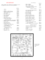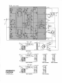
1
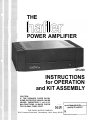
THE
POWER AMPLIFIER
INSTRUCTIONS
for OPERATION
and KIT ASSEMBLY
CAUTION:
IF THE SPEAKER FUSES BLOW,
SOME DISTORTED SOUND CAN BE
HEARD. THEREFORE IF AMPLIFIER
MALFUNCTIONS, ALWAYS CHECK
FOR BLOWN FUSES FIRST.
serial
number in all communications
THE DAVID HAFLER COMPANY
5910 Crescent Boulevard, Pennsauken, New Jersey 08109
Hafler DH-200 Power Amplifier
INTRODUCTION
The Hafler DH-220 is a two channel audio power amplifier
designed to the very highest performance standards. It is
available either as a kit, or fully assembled. Its 115 watt per
channel power rating is sufficient for driving all loudspeakers in
home applications, and its design assures extremely low distortion of all types. A combination of high performance, dependability, reliability, and moderate price is in the Hafler tradition of
using the very latest technology to provide outstanding value.
The DH-220 circuit is a refinement of the DH-200 design, a
Hafler landmark which has achieved worldwide recognition,
and has elicited glowing reviews since its 1979 introduction. As
in the DH-110 preamplifier, particular attention has been paid to
component quality, using polypropylene or film capacitors
wherever feasible, for example, for superior sound.
Combining the latest power MOSFET technology with uniquely simple and effective circuit topology reduces distortion of
all types, and at all power levels, over the full audio frequency
spectrum, to the vanishing point. In addition to its pace-setting
performance achievements, the conservative mode of operation accomplishes a new high in long term reliability and exceptional resistance to abusive operating conditions. This is one of
the direct benefits of MOSFET utilization in overcoming a
serious limitation of conventional transistors - their tendency
to self-destruct under other than normal operating conditions.
So rugged is the DH-220 that it can deliver more than ten
amperes into a short circuit!
The speed - measured as the slew rate - of this design
delivers unmatched transient linearity, revealing the most
delicate shadings, textures and nuances of the music, surpassing
the capabilities of the most revealing loudspeakers and cartridges by a wide margin. Coupled with its unconditional stability, and ability to deliver adequate power into any loudspeaker
load, the result is absolute freedom from listening fatigue. The
longer you listen to this phenomenal amplifier, the more certain
you will be that you could not have made a better choice.
The oversized power transformer and bridge rectifier; the
massive heat sinks; the conservative operating levels of the
MOSFET output devices - all are evidence of the design efforts
to achieve exceptional reliability simultaneously with state of
the art sonics and specifications. And this circuit is convertible to
a high power monophonic amplifier with comparable stability
and specifications.
The fully complementary, symmetrical push-pull circuit,
which is direct coupled throughout (except at the input), incorporates all silicon devices in a format which is directly related to
the highly acclaimed DH-110
DH-110 preamplifier. Its unique selfprotecting output stage prevents the thermal runaway which is
a common threat to solid state amplifiers. The ruggedness and
conservative operation of the output stage allows the DH-220 to
avoid the need for special protective circuits which could compromise audio performance. Basic protective systems provide
maximum security against malfunction damage to the amplifier
or the speaker: the AC line fuse, B + fuses, thermal breakers,
and loudspeaker fuses. Nothing hinders the essential purity of
the audio signal.
Those who use these instructions to assemble the DH-220 kit
will find that the left and right audio modules (printed circuit and
heat sink assemblies) are preassembled and pretested. This
greatly simplifies the kit assembly so that it can be done in only a
few hours without special skills or know-how. Because of the
modular arrangement, it is possible to operate on one channel if
the other requires service, and avoids the need to return the entire amplifier in cases where only one channel is at fault.
Accessories for special applications include provision for
monophonic use; a panel for standard 19” rack mounting; and
an alternative power transformer for international AC line
voltages.
Through advanced engineering geared to the audio perfectionist, and an efficient no-frills approach, Hafler is making high
technology high fidelity affordable.
CONTENTS
Operation . . . . . . . . . . . . . . . . . . . . . . . . Page 3
Assembly Instructions .................. 4
Wiring the Kit ...................... 6
If Problems Arise. ..................... 10
Service and Warranty .................. 11
Copyright 1984, All rights reserved.
AC Line Connections for Overseas Use. ... 12
Kit Parts List ......................... 13
Schematic Diagram ................... 1 4
Component Value Listing. .............. 15
Pictorial Diagram. .................. Insert
INSTALLATION
The DH-220 is most likely to be installed out of sight in most
applications, since its power may be controlled by the AC
switching of most audio preamplifiers, like the Hafler DH-110. If
your control unit does not provide switching capacity sufficient
for the amplifier’s 7 amp needs (plus other equipment it is also
switching), you should use the amplifier’s own power switch. In
that case, turn on the preamplifier first; then turn the amplifier
on a few seconds after the preamp has been turned on, to avoid
any unnecessary turn-on transients from some preamplifiers.
Likewise, switch the power amplifier off first.
Be sure to provide sufficient ventilation for the amplifier.
Unobstructed air circulation around the finned heat sinks and
above the amplifier is important for long, trouble-free life. Never
put anything on top of the cover perforations. It is normal for the
top and the heat sinks to become warm in use.
If the amplifier is to be installed close to a record player, you
should first check its position for freedom from hum pickup by
the cartridge from the field radiated by the power transformer
of the DH-220. Although the design of the transformer
minimizes such radiation, certain cartridges are more sensitive
It is expected that the amplifier will always be resting on its
feet, which should be on a hard enough surface that air flow
underneath is not obstructed. If it is mounted in a rack, or
through a panel, the feet may be removed so long as adequate
ventilation is provided through the bottom openings.
than others, and require separation from the amplifier. Check at
a comparatively high volume setting, and while swinging the
tone arm throughout its arc. Often a few inches additional spacing will eliminate the problem.
OPERATION
The red pilot lamp which is integral with the power switch
glows whenever the amplifier is turned on. A blown AC line fuse
is the most likely cause if it is not illuminated when the amplifier
is switched on.
The pilot lamp also provides a high temperature indication. In
the unlikely event that the amplifier ceases to function, and the
amp blinks on and off steadily, it indicates that one of the thermal breakers has shut down the amplifier because of excessive
temperature rise in a heat sink. When the heat has dissipated in
a few minutes, the amplifier should return to normal operation.
If the lamp again blinks, check for insufficient ventilation, or an
excessive input signal, or an input which may have dangerous
signal content (such as oscillation). Failing evidence of this, the
amplifier may have malfunctioned. Because of the very large
heat sinks, it is highly unlikely that any normal signal will cause
the amplifier to overheat.
Loudspeaker Fuse Selection
The DH-220 power amplifier is supplied with 2 amp fuses in
the speaker lines. Experience has shown that since an overload
must exist for a few seconds for a fuse to blow, a 2 amp fuse will
protect most speaker systems, and only blow when overload occurs. Smaller fuses tend to blow too easily, and larger fuses do
not adequately protect most speaker systems.
A pair of 5 amp fuses are also supplied as alternatives for the
speaker fuse holders. These should be substituted if the power
output of the amplifier is to be tested, and these or intermediate
values may be used if the amplifier is to be operated at very high
power levels into 4 ohm loads.
If the manufacturer of your speakers recommends a specific
value of fuse for their protection, we suggest that you obtain
A C fuses of that value and install them in the back panel.
Loudspeaker Power Ratings
There are no U.S. standards for rating the power handling of
loudspeakers. As a result, the manufacturers’ usual “music
power” ratings, or suggested amplifier limits, are of only
minimal help in determining safe operating levels with
amplifiers which can deliver substantial amounts of power. You
must take into consideration the type of music, and the levels
you like, to provide long term trouble-free operation of your
speaker choice, when you have a sizeable amplifier like the
DH-220.
Connections
AC
The AC power cord should be plugged into 120 volts, 60 Hz,
on the switched outlet of a preamplifier which can provide at
least 7 amps, or 840 watts. Then the amplifier power switch may
be left on, and it will be controlled by the rest of the system. Or. it
may be plugged into a 120 volt wall outlet, and switched on and
off independently.
If your line (mains) voltage is different, be sure you have the
alternate power transformer which can accommodate several
line voltages, and be sure it is wired for your mains voltage as
described later in this manual before you pIug in the amplifier.
Input
Conventional shielded cables, such as those supplied with
your preamplifier, provide the input signal to the sockets on the
back panel of the DH-220. Be sure that the outer shield connection is secure, to avoid hum. The length of these cables (so as to
permit remote location of the amplifier, if desired) is limited only
by the output impedance of the preamplifier. If it is 600 ohms or
less, as with the DH-101
DH-101 and DH-110 Hafler preamps, for instance, cable lengths up to 50 feet are premissible without loss of
performance. Special low capacitance cables enable even
greater distance between preamp and amplifier. It is desirable
to keep the left and right input cables close together throughout
their length to minimize the likelihood of hum pickup. Also, you
should avoid running them parallel to AC cords - these should
be crossed at right angles.
Output
The loudspeakers (or headphones) connect to the red and
black terminals on the back panel. These binding posts provide
several convenient alternative connecting methods. The screw
cap may clamp the bared wire end, or a “spade lug” attached to
it, but a better connection will be made by locating the hole drilled through the shaft of the terminal when the cap is unscrewed.
Insert the twisted end of the bared wire so that the cap will
clamp it in place. Always be sure that no strands of wire are
unsecured, and that the bared end is not too long to risk contacting other elements. A soldered end or fitting is the safest solution.
These terminals also accept standard plug-in “banana pin connectors,” including the double ones with standard 3/4” spacing,
available from electronic supply houses. These are the most
convenient, especially if you may wish to interchange speakers
occasionally.
It is important to maintain correct phasing of the speakers
when making their connections. Some speaker terminals are
coded red and black, or + and -, etc. It is important that the
“sense” of one speaker’s connections match the others. If one is
reversed, you will find that the sonic image has a “hole in the
middle,” and that it is deficient in bass. Speaker wire always
identifies one conductor to make this easy. There may be a
molded ridge in one lead, or the color of the insulation on one
wire is different, or the wire itself may be color coded. If pin
plugs are used, be sure they are color coded, or that you follow
the indexing mark on one side of the double connectors.
Select speaker wire of sufficient size to preserve the high
damping factor (and excellent speaker control) of your
amplifier. Standard 18 gauge lamp cord (“zipcord”) is satisfactory for distances up to 30 feet for an 8 ohm speaker. As the
distance increases, larger wire sizes are recommended. The
next larger wire size is #16, and it is often preferred by perfectionists. If you have 4 ohm speakers, the maximum cable length
for best results is halved.
The black output terminals are electrically connected to the
chassis internally. Be certain that when the amplifier is operated
in its normal stereo mode that the red output terminals are never
connected together. In the special case when the amplifier has
been internally modified for monophonic bridged operation,
the output is taken from the two red terminals only. Then, the
black terminals are left unconnected.
Headphones are normally operated from the loudspeaker
outputs, but are usually connected through a junction box
which provides switching from phones to speakers. Such a box
usually provides some added resistance to reduce the sensitivity
of the phones, and thus minimize the likelihood of hearing component noise, because of the low setting required at the volume
control. Some headphone boxes utilize a “common ground”
system which makes it particularly important that you carefully
observe the proper connections. While the black ground terminals can be connected together, the red ones must not be.
Some headphones, such as electrostatic types, are less sensitive and may need little or no resistance in series for normal
operation. These could be easily interchanged with the
speakers through the use of double banana plugs.
KIT ASSEMBLY INSTRUCTIONS
There are three basic rules for success in electronic kit
building:
1. Read the instructions carefully, and follow them in order.
2. Make secure solder connections which are bright and
smooth.
3. Check your work carefully after each step.
The DH-220 amplifier is a versatile component with
sophisticated circuitry which has been made remarkably easy
to build by individuals with many years of experience in the
design and engineering of the finest performing audio kits, and
in the preparation of their manuals.
Kit building should be fun, and we are certain you will find this
to be so. Assembly will be faster, easier, and more enjoyable if
you have someone help you by reading the steps aloud, selecting the required parts, and preparing the necessary wire
lengths in advance as you proceed. Fatigue increases the risk of
error, so take a break rather than push to early completion.
There are relatively few separate components in this design, to
make it easy to pack everything away, if need be.
Your work area should have good lighting, the proper tools,
and a place where the large pictorial diagram can be positioned
within easy reach for checking. The tools should include:
1, A 40 to 100 watt soldering iron with a 1/4" or smaller tip which
reaches at least 600°F.
2. 60/40 (60% tin) ROSIN CORE solder, 1/16" diameter or
smaller. (Smaller diameters are easier to work with.)
3. A damp sponge or cloth to wipe the hot top of the iron.
4. A wire stripping tool for removing insulation. This can be a
single-edge razor blade, but inexpensive stripping tools are
safer, faster and easier.
5. A medium-blade screwdriver (about 1/4" wide).
6. Needle-nose pliers (a long, narrow tip).
7. Diagonal or side-cutting small pliers.
8. Large “gas” or “slip-joint” pliers.
9. A 1/4" “Spin-tite” nut driver may be helpful, but is not
necessary.
A soldering “gun” is not recommended. The unfamiliar user is
more likely to damage the etched circuit boards with its higher
heat potential and unbalanced weight. Also, because he may
not wait long enough for it to reach operating temperature each
time it is switched on, poor solder connections are more likely.
Pencil irons are much lighter and easier to use, and there is no
waiting time when solder connections follow in sequence, as in
kit building. Make sure you have a holder for it, though, and
always unplug it when you take a break.
few seconds to allow a good bond. When cool, check the connection by wiggling the wire. If in doubt, or if the connection is
not shiny, re-heat the joint. Excess solder may be removed from
a connection by heating it and allowing the solder to flow onto
the iron, which is then wiped on the sponge.
ALL SOLDER USED MUST BE ROSIN CORE.
Never use acid core solder or any separate flux in electronic
work. Silver solder is also not suitable. If in doubt about unmarked solder, always obtain a fresh supply of rosin core solder. We
recommend 60/40 for easiest use. Do not confuse it with 40/60,
which is harder to melt.
Proper Soldering
There are four steps to making a good solder connection:
The general procedure is to use a hot iron for a short time to
heat a connection, then add solder with the iron still in contact.
Remove the solder once it flows, and then remove the iron. A
cooler iron applied for a longer time is more likely to damage
components, or lift the copper circuit pattern from the boards. A
break in the etched circuit can be mended by simply soldering a
small piece of wire across it. Do not allow much build-up of
solder on the tip of the iron, or it may fall into adjacent circuitry.
Make a good mechanical connection to hold the wire in position while heat and solder is applied.
Heat thejunction of the wire and lug, or hole, with the bright,
shiny top of the iron.
After heating for a couple seconds, apply solder to the junction. It should melt immediately and flow smoothly around
both surfaces.
When soldering to a numbered hole on the board, insert the
wire from the components side, and apply the iron, leaving
some bare wire exposed so that you can see that the hole is then
filled with solder for a secure bond. A round wooden toothpick
is suggested so that you can heat and clear the hole of solder if it
hinders your inserting the wire. Some builders prefer to clear
every hole first with a touch of the iron and toothpick. If the wire
has first been “tinned,” no additional solder may be necessary if
solder fills the hole, but it is good practice to push the wire
through, and then back it up a bit, to be sure solder fills the hole
from both sides. Make certain a bright, shiny flow is evident
from the wire, across the hole, onto the circuit pattern on the
board.
Allow the connection to cool undisturbed.
Remember that the connection is made by the solder, not by
mechanically attaching the wire to the terminal. Usually the
wire is looped through the lug and crimped in place, but some
prefer to just place it through the hole and rely on the stiffness of
the wire to hold it while soldering. Connections to numbered
holes on the circuit board are handled this way.
Good solder connections are essential for trouble-free noisefree operation. A good solder joint does not require much solder
around the conductors. Never “butter” partially melted solder
on the joint, as it is useless. A good connection looks smooth and
bright because the solder flows into every crevice when the
parts are hot enough. The iron must have a bright, shiny tip to
transfer heat easily to the junction. That’s why the damp sponge
should be used frequently to wipe the tip, and occasionally you
must add a small amount of solder to the tip, too. If a connection
is difficult to heat, “wet” the tip with a small blob of solder to provide a bigger contact surface to the joint. Once the solder flows
around the conductors, any movement must be avoided for a
“Tinning” refers to the process of applying a light coating of
solder to the bared wire end. This keeps all the strands secured,
and also makes a good connection easier. Simply touch the wire
with the iron for a couple of seconds, and apply solder. Allow the
excess to flow away onto the iron. When properly done, the
wire is uniformly bright, and no larger than before. The hookup
wire supplied with this kit does not normally need tinning, for it
is pre-tinned.
5
find it easier to first start them with a regular screwdriver, to set
the thread, and then use the more convenient nut driver, if one
is available.
Wiring the Kit
If any components are unfamiliar to you, checking the pictorial diagram should quickly identify them. Or, the quantities,
and the process of elimination as you check the parts list, will
help. The pictorial diagram is necessarily distorted to some extent for clarity, so that you can trace every wire in a single
overall view for verification as you work. You may wish to
check off on the diagram as you solder each location.
Mechanical Assembly
1 r When you unpack your kit, you will find that the
transformer, large capacitors, and the output assemblies
have been temporarily fastened to the chassis for safe
shipment. Disengage these, and include this hardware
with the rest when you check off the components
against the parts list in the back of the manual. We
recommend this check-off to be sure you have
everything, and to enable you to identify any unfamiliar
items by comparing them with the pictorial diagram. An
egg carton is ideal for keeping hardware items
separated.
To “prepare” a wire means to cut the designated length from
the coil of that color, and strip about 1/4" of insulation from each
end. The wire supplied in the kit is #18, so you can set adjustable
wire-strippers accordingly. The transformer leads are #16 or
#18 and the line cord is #16. Be careful that you do not nick the
wire when you strip it (that can happen more easily if you do not
use wire strippers) for that weakens it. The wire supplied in this
kit is “bonded stranded,” which provides exceptional flexibility
with resistance to breakage for easier use, and it is pre-tinned.
A “set” of hardware includes one screw and one KEP nut (with
its attached lockwasher). Always install the lockwasher side of
the nut first. If the size of the hardware is not specified, use the #6
size. The smallest size is #4 and #lO the largest. Always insert
the screw from the outside of the chassis.
Whenever a connection is to be soldered, the instructions will
so state, or indicate by the symbol (S). If more than one wire is to
be soldered to the same terminal, they will be indicated by (S-2),
(S3), etc. If soldering is not called for, other connections have
yet to be made to that terminal. They would be more difficult if
the connection was already soldered. Every connection in the
kit will be soldered when it is complete. After soldering a connection, it is best to clip off any excess lead length to minimize
the possibility of a short circuit (as on switch lugs, where terminals are very close together), and for a neat appearance.
It will simplify matters if you first separate the #4 nuts from the
#6 nuts, which have the same outside dimensions. A #4 screw
will pass through a #6 nut, aiding identification.
2 L Select the four rubber feet, four sets of # 6 hardware, and
the chassis. Insert each screw through a foot so that the
head is recessed, and install the feet on the outside at
each corner hole.
Be sure that uninsulated wires cannot touch adjacent terminals or the chassis metalwork.
The symbol (#) indicates a connection is to be made to that
point. When a lug number is specified without (#) it is simply a
locating reference.
3 1 Select th e two red output terminals. Install them in the
sequence shown below, in the two center holes LR and
RR marked ' +’at the rear of the chassis. Before you fully
tighten the first nut, unscrew the cap to expose the hole
drilled through the threaded shaft. Connection of loudspeaker wires will be easier if these holes are positioned
vertically. A nail through the hole will keep it positioned
while the hardware is tightened. Each connecting lug
should point downward before the last nut is secured. Be
sure both nuts on each terminal are tight, as they are difficult to reach when the amplifier is completed.
When the instructions call for twisting two or three wires
together, the length of wire indicated anticipates a fairly tight,
uniform twist by hand, of three full turns every two inches. If
you find the wires too short, loosening the twist will gain some
needed length.
Handle the circuit boards carefully. They represent a major
part of the kit cost. Stand-up components, such as transistors,
should be checked when you install the module, to be sure all
leads are separated.
All of the active circuitry is contained on the PC-19 board,
which has been carefully tested to assure that it meets every
specification. Only the interconnection of power supply
elements is left to the builder. Take the time to be accurate and
neat, and you can be sure that your completed amplifier will
meet the performance of a factory assembled unit, and can continue to perform properly for years to come. Check your work,
and make sure the entire step has been completed before placing a check mark in the space provided, and continuing on to
the next step.
4 Select the two black output terminals and install them or
either side of the red ones, at LB and RR. Be sure the
shaft holes are vertical, the lugs point downward. and
each nut is tight.
KEP nuts have been supplied as a convenience. These have
lockwashers attached, and the lockwasher always goes onto the
screw first. If the sheet metal screws have hex heads, you may
6
5 n Select the two round fuse holders, and two each 1/2” rubber washers, lockwashers and nuts. First install the rubber washer on the holder, so it will be outside the chassis,
and then fasten the fuse holders at LF and RF, with the
tip lugs pointing towards each other, toward the center
of the chassis.
6 U Select the two input sockets and 4 sets of #4 hardware.
Install the sockets inside the chassis at LS and RS so that
the short lug of each socket is near the hole between the
two sockets.
7 0 Select the single ground lug (with lockwasher teeth) and
one set of #4 hardware. Install it between the input
sockets, pointing toward the bottom. Bend it out for access, and twist it 90° for easier insertion of a wire later.
Be sure this lug is tight, as the locking teeth must cut
through the chassis paint for a good ground connection.
8 ri Select the four-lug diode block DB, the long # 6 screw,
and a nut. Install the rectifier in the center hole near the
rear of the chassis, with the plus (+) terminal located
over the tiny indexing hole at position four. Correct
orientation of this rectifier is essential for proper wiring.
9 n Select the single fuse clip, and one set of #4 hardware. Install the clip in the right front chassis hole FC, closest to
the foot.
10 0 Select the two dual fuse clips and four sets of #4 hardware. Install these in the pairs of holes FL and FR on
either side of the center of the chassis.
11 0 Select the 5-lug terminal strip and two sets of #4 hardware. Install it in the front holes TS, next to the single
fuse clip. Note the position of the mounting lugs (to the
right) in the pictorial diagram.
NOTE: Kits provided with the multiple voltage power transformer
for use in locations outside the United States having a line (mains)
voltage other than 120 VAC are also supplied with an additional twolug terminal strip which is to be installed using an additional set of #4
hardware on the other side of the chassis, below the dual fuse clip FL.
12 0 Select the power switch. Install it with the red window to
your right as viewed from the front. The switch snaps
into chassis hole PS from the outside.
13 q
Select the AC line cord and the plastic strain relief.
Separate the two conductors for 2”. Cut 1” off one of the
two leads, and strip 1/4" of insulation from each lead.
Twist the strands tightly, and tin each end. Make a sharp
'V' in the cord 8 1/2" from the longest cut end by bending it
back on itself. Install the relief with the small end nearest
the cut end of the cord. Crimp the two halves of the relief
around the wire at the 'V' with heavy pliers, to partially
form it before insertion into back panel hole AC. Then
grip the larger diameter with the plier tips, squeeze it
tightly, and insert the cord and the relief from the outside. A flat side of the relief mates with the hole shape,
and it snaps into position when fully inserted.
Connect the shorter lead to FC lug #l. (S). Connect the
longer lead to the lower hole of TS lug #2. (S). Note that
lug 2 is the second protruding lug on the terminal strip. It
is not the mounting bracket for the terminal strip.
Soldering this lead to the lower hole now will make later
connections to the top portion of the lug easier. Be sure
no stray strands of either line cord conductor are left
unsoldered.
14
Prepare a 6 1/2" green wire. Connect one end to dual fuse
clip FL lug #l. Connect the other end to the other dual
clip FR lug #l. (S).
15
Prepare a 6 1/2" white wire, Connect one end to FR lug #3.
Connect the other end to FL lug #3. (S).
16
Prepare two 7” white wires. Start with one wire projecting 3/4" beyond the other, and twist them uniformly
together throughout their length. Connect the projecting end to RF lug #l. (S). Connect the corresponding end
of the other wire to RFlug #2. (S). Place this pair over the
right edge of the chassis.
170 Prepare two more 7” white wires. Start as before with
one wire 3/4" longer, and twist them together. Connect
the longer end to LF lug #2 (S). Connect the other wire to
LF lug #l. (S). Place these wires off to the left.
18 0 Prepare an 8” green wire and a 10” white wire. Start
with the white wire 3/4” longer than the green wire, and
twist them uniformly together. Connect one end of the
green wire to the lug on black output terminal LB. Connect the corresponding end of the white wire to red
terminal LR. (S). Place these wires off to the left.
shorter, middle set of tabs tightly around the bare wire,
and then bend the longer tabs around the insulation.
Then flow solder into the joint around the bare wire,
keeping the solder away from the spade section.
19 c3 Prepare a 7” green wire. Connect one end to terminal
LB. (S-2). Place this wire towards the center of the
chassis.
20 Ll Prepare a 10” white wire and a 10” green wire. Starting
with the white wire 3/4" longer, twist them together. Connect the projecting white wire to red terminal RR. (S).
Connect the green wire to terminal RB. Place these
wires off to the right.
29
Prepare a 2” white wire. Connect one end to FC lug #2.
(S). Select another spade lug, and solder it to the other
end. Connect it to the PS middle lug.
30 0 Select the 0.39 mfd (.39K) capacitor and trim its leads to
1/2" Connect one lead to TS lug #4. (S3). Connect the
other lead to TS lug #5.
2 1 C Prepare a 51/2" green wire. Connect one end to terminal
RB. (S-2). Place this wire towards the center of the
chassis.
31 0 Select the two large round capacitor brackets, the two
large capacitors, and 6 sets of #6 hardware. Place a
bracket around the bottom of each capacitor, and fasten
it snugly with one set of hardware through the clamp.
Note the direction of insertion of the screw for easy servicing access in the future. The clamps need not be
tightened now - just made snug. Place each assembly
on the chassis, at CL and CR, noting the position of the
clamp, and fasten them securely. Be sure no wires are
trapped by the bracket. Then loosen the clamps, and
position the capacitors so that each + terminal is positioned as in the pictorial diagram. The + terminal will
usually be so marked, but if not, it may be identified by a
red dot. Note that the + terminal of CL is nearest the terminal of CR. Make sure the capacitors are seated
against the chassis and tighten both clamps.
22 0 Prepare a 16” green wire, but strip 1 1/4" of insulation
from one end. Prepare a 15” white wire. Start with the
normally stripped (l/4”) ends even, and twist these wires
uniformly together. Thread the longer bared end of the
green wire through LS short lug #2 from the top left,
then through GLlug #3, and connect it to RSshort lug #4.
Solder only LS lug #2. Connect the corresponding end of
the white wire to LS lug #l. (S). Place this wire up under
the chassis rear lip, above the output terminals, and off
to the left.
23 L! Prepare a 6 1/2" green wire. Connect one end to CL lug
#3. (S2). Place this wire over the rear of the chassis.
24 C Prepare a 10” green wire and a 10” white wire. Twist
these together with the ends even. Connect the green
wire from the right to RS short lug #4. (S-2). Connect the
white wire to RS lug #5. (S). Place these wires off to the
right.
32 0 Select the 4 plain solder lugs and then 4 short #lO SEMS
screws (with lockwasher attached). Install these in the
capacitors, with the lugs pointing as in the diagram.
33 C Prepare a 6” green wire. Connect one end to DB lug #l.
(S). Connect the other end to CL lug #l.
25 0 Prepare two 22” white wires, and twist them together
throughout their length. 8” in from one end of the pair,
cut one of the wires, and unwind it about 11/2" in each
direction from the cut. Strip 1/4" of insulation from each
of these cut ends. Place the longer portion of the wire
along the lower front edge of the chassis, with the break
at the terminal strip TS. Connect the cut end from the left
to TS lug #2. Connect the other end to the lower hole of
TS lug #5. (S). Place this pair along the front edge of the
chassis, under the power switch, with the ends projecting from the front corners of the chassis.
34 E Prepare a 4%” green wire. Connect one end to FL lug #l .
(S-2). Connect the other end to CL lug #l. (S2).
35 G Prepare a 6” white wire. Connect one end to DB lug #4.
(S). Be sure this is the + terminal of the rectifier. Connect
the other end to CR lug #2.
36 q
26 il Select a 1 megohm resistor (brown-black-green) and
trim the leads to 1/2”. Connect one lead to TS lug #2. (S3).
One of these 3 leads has already been soldered to the
lower lug hole. Connect the other lead to TS lug #3.
Prepare a 4 3/4" white wire. Connect one end to FRlug #3.
(S-2). Connect the other end to CR lug #2. (S2).
37 •1 Remove all insulation from a 3” white wire. Connect one
end to CL lug #2. (S). Connect the other end to CR lug #l.
(S).
38 [7 Select the power transformer, the 4 flat washers, and the
4 sets of #10 hardware. Position the transformer with
the red leads to the center rear of the chassis, and the
black and black/white leads towards the power switch.
If the transformer is the special multiple voltage version,
the additional leads should be placed as shown elsewhere in this manual for the desired line (mains) voltage.
27 n Select the diode and trim its leads to 1/2”. Note that one
end of the diode is marked with a stripe (or an arrow
head will point to that end). Connect the marked end to
TS lug #4. Connect the other lead to TS lug #3. (S2).
28 0 Prepare a 4” green wire. Connect one end to TS lug #4.
Select a spade connecting lug, and solder it to the other
end. Place this wire down against the chassis, and connect it to the PS lug on the right, near the edge of the
chassis.
The red/yellow lead will likely be the correct length. If
you wish to shorten the red leads for neatness in connecting them to the rectifier terminals, it is easier to strip
them before the transformer is mounted.
The proper way to attach a spade lug to a wire is to first
cut the bared wire end to the right length (no more than
1/4" so that the insulation will be securely gripped by the
longer, outer tabs, while the wire does not protrude into
the spade clamp area. Tin the bare wire end. Bend the
Place the white pair of wires under the front chassis lip.
Install a flat washer on top of each transformer foot after
the screw is inserted from below, and then add the nut.
Be sure no wires are trapped.
8
these. If it is filled with solder, running the iron along the
underside will uncover the hole, and it may be cleared
with a wooden toothpick.
The transformer leads may be trimmed as desired for a neat job,
but be sure you do not cut any of them too short (particularly if
yours is the multi-voltage version, and any change to a different
supply voltage is likely). Cutting the leads too short for re-use
may void its warranty, if it is thought to be defective. Consult the
multi-voltage diagrams elsewhere in this manual fcr connections to the terminal strips which may differ from the stepbystep instructions here.
Now position the right module (with the breaker at the
front when the long bottom row of eyelets is next to the
chassis) with the circuit board up, against the side of the
chassis.
Wires will be connected to the holes from the top of the board,
and you must be sure they are soldered securely to the bright
circuit ‘pads’. Each hole is ‘plated through’ - it makes a connection to the other side of the board - and a good solder connection which heats the wire and the circuit pad properly will allow
solder to flow through the hole for a secure connection.
Be sure all strands of each transformer lead are tinned and
soldered together before connection to a lug, so that there is no
possibility of a stray strand touching anything but the lug.
39 0 Select the remaining spade lug, and solder it to the black
transformer lead. Connect it to the PS left lug.
Even though the connecting wires are just long enough to make
the connections now, they will be rather long when the
amplifier is completed. That is why working room is limited.
Any wire which is to be connected to a hole on the board should
have a tight, tinned end. The wire supplied in the kit is already
tinned, so it would not normally require additional tinning
unless the tip is frayed. Melt a small amount of solder on the tip
of the iron so that it will make a good contact with both the
bared wire end, and the circuit pad as the wire is inserted into
the hole. Then add additional solder so that there is a smooth,
bright transition from the wire to the board as it cools undisturbed. If you must use a great deal of heat on a connection, make
sure that you have not loosened any adjacent connections in the
process - especially wires from the back side of the board.
4 0 u Select the .005 (502M) disc capacitor, and trim its leads to
l/2” or less. Wrap one lead around the shaft of the spade
lug which is connected to the PS left (inside) lug. Wrap
the other lead around the shaft of the spade lug connected to the middle lug. Solder both leads. Be sure
there is adequate clearance between these connections,
and that the spade lugs are fully engaged.
41
Connect the black/white transformer lead to TS lug #5.
(S3). One of these wires was previously soldered to the
lower hole of this lug.
42 G Twist together the two red transformer leads for
neatness, and connect one iead to DB lug #2. Connect
the other to DB lug #3.
The holes #lo and #3 are very close to capacitors on the board.
Be sure heat does not damage these capacitors.
4 3 ci Select the .Ol mfd (103M) disc capacitor, and trim its
leads to 3/4" Strip two 1/2” pieces of insulation from the
green wire, and slide one piece over each of the
capacitor leads. Connect one lead to DB lug #2. (S-2)
Connect the other lead to DB lug #3. (S-2) Make sure
both leads are securely soldered to each lug. Here you
could overlook a poor connection.
49 II Prepare a 51/2" green wire. Connect one end to hole #lO
on the circuit board. (S). Make sure it cannot contact the
transistor mounting screw near the underside. Connect
the other end to FR lug # 2 (S).
44 0 Connect the red/yellow transformer lead to the center
of the bare wire between the capacitor lugs. (S). Lowest
hum in the unit will be attained when all of the wires
which connect here are as close to the center of this wire
as possible.
50 0 Prepare a 6” white wire. Connect one end to hole #3. (S).
Connect the other end to FR lug #4. (s).
51 C Select the green and white twisted pair from the output
terminals RR and RB. Connect the white wire to hole #5.
(S). Connect the green wire to hole # 7 (S).
45 17 Connect the single green wire from output terminal LB
to the center of the bare wire next to the transformer
lead. (S).
4 6 0 Connect the single green wire from RB to the center of
the bare wire on the other side of the transformer lead.
(S).
47 q Connect the green wire from CL lug #3 between the two
input sockets to the center of the bare wire also. (S).
4 8 0 Select the output assembly modules (the two major
items in the kit). You will note that the only difference,
which identifies the left or the right module, is the position of the thermal breaker, which is located between
one pair of output transistors on the heat sink rib. Before
connecting wires to these modules it is best that you take
the time to inspect the underside of the bottom row of
holes to make certain that connections already made to
some of these are well soldered. You will be making connections from the top side to holes 3,5,6,7,8 and 10.
Make sure the proper connection point is clear at each of
9
52 q
Select the pair of white wires from RF. Connect the
shorter wire to hole #6. (S). Connect the other wire to
hole #8 (S).
53
Select 4 of the long sheet metal screws. Take care to see
that no wires are trapped in the process, while you tilt up
the module and fasten it to the end of the chassis. The
screws are inserted between the heat sink fins, and then
engage the chassis.
54 0 Select the green and white pair of wires from input
socket RS. Connect the white wire from the left to the
top (rear) hole #l. (S). Connect the green wire to hole #2.
(S). These wires should be soldered to the circuitry on the
underside of the board, although they are connected
from the top side of the board, assuring a good connection. These wires will be specifically positioned later,
though they now seem long.
55 I Select the white pair of wires at the front of the chassis.
Tuck the excess-wire into the corner and connect one
wire to each of the lugs on the thermal breaker. Solder
each.
56 [
Select the left output module, check it as before to see
that underside connections near the holes are secure,
and that the holes are visible. Place it against the left side
of the chassis with the breaker at the front, board up.
57 :
Prepare a 6” green wire. Connect one end to hole #lo.
(S). Be sure it cannot touch the transistor mounting
screw! Connect the other end to FL lug #2. (S).
58 :
green ground leads from the black output terminals and
the ground lug should be brought together through most
of their length.
Select the green and white pair from output terminals
LB and LR. Connect the green wire to hole #7. (S). Connect the white wire to hole #5. (S).
Prepare a 5 1/2 white wire. Connect one end to hole 3.
(S). Connect the other end to FL lug #4. (S).
61 1
Select 4 sheet metal screws and fasten the module to the
chassis, making sure no wires are trapped.
Check all your soldered connections - especially those
on the fuse clip lugs, which are sometines difficult to
solder to. Clip off any excess bare wire which could short
to adjacent lugs or the chassis. Pay particular attention
to the stranded wires from the transformer and line
cord, and check the power switch connections. Now
turn the amplifier upside down and shake out any bits of
wire or solder.
69 q
Slide the cover in place, and install it with the eight sheet
metal screws.
70 0 Remove the backing from the serial number label, and
apply it to the bottom at the center rear. (This may have
already been done at the factory.)
59 I Select the white pair from LF. Connect the shorter wire
to hole #8 (S). connect the other wire to hole #6 (S).
60 :
68
IF PROBLEMS ARISE
Each circuit module, which comprises all the “active”
amplifier circuitry, has been incircuit tested to standards identical to factory built amplifiers, prior to being packed in a kit.
Thus, with careful assembly, the likelihood of a circuit fault is
near zero. If you are certain the problem lies in the power
amplifier, check the pilot lamp. If it is blinking, excessive
temperature has shut down the amplifier. After a few minutes to
cool, it will turn on automatically. If it soon shuts down again,
and the amplifier has sufficient ventilation, the malfunction is
either internal, or the result of an excessive (and very likely
inaudible) input signal. In that case, the source must be
investigated.
62 ! Select the green and white pair from input socket LS.
Connect the green wire to the top rear hole #2. (S). Connect the white wire to hole #l. (S). Solder these on the
back of the board.
63 I ! Tuck the excess of the remaining white pair of wires into
the front corner, and connect one wire to each lug of the
thermal breaker. Solder each.
64 : : Select the 7 ampere slo-bid fuse (a slo-bid fuse has distinctive internal construction) and install it in the single fuse
clip FC.
If the pilot lamp is not lighted, the main fuse in the single fuse
clip near the power switch is probably open. If a replacement 7
ampere Slo-Blo fuse (do not use a larger value) also blows, the
amplifier has a power supply problem, and requires professional service.
65 C Select four 5 amp regular fuses, and install them in the
dual fuse clips FL and FR.
If there is a problem in only one channel of the amplifier, that
channel may be isolated by removing the power supply fuses in
the adjacent dual fuse clip, and the other channel may be used
monophonically. We do not encourage local service of this
amplifier because some components may not be available locally, and substitutions are not recommended at all. You may
return a defective module for factory service. This reduces shipping weight and the likelihood of damage. To remove the
module (leave the heat sink attached to the circuit board) tag
each wire with the circuit board hole number as you unsolder it
from the board, and insulate each bare wire end. It is safer to
also remove the power supply fuses from that channel. The
wires to the thermal breaker must be temporarily soldered
together, and insulated.
66 0 Select the two 2 amp fuses, and install them in the twist
type fuse holders on the back panel. These fuses will provide reasonable protection for most speakers. See the
Operation section of this manual for more detailed information. The remaining 5 amp fuses are alternates for
the back panel holders for high power test purposes.
67 0 For lowest distortion performance and lowest noise, correct placement of some wires is important. The wires
from the output terminals and the back panel fuse
holders should be kept against the chassis. The input
socket pairs should be about an inch above the chassis,
(the left pair can be tucked under the rear chassis lip),
and should turn upwards at the bottom center of the circuit board, about 1/2" to 1” off the board, in the plane
defined by the edges of the finned heat sinks. The wires
to the dual fuse clips should be kept away from the board
and against the chassis, bringing the excess length forward of the fuses. The leads to the power supply
capacitors should be kept away from the boards. The
Adjustments for Bias and DC Offset
These two potentiometers on each circuit board have been
set at the factory and should not normally require adjustment
for the life of the amplifier. In the event of repairs such as transistor replacement, the following is the procedure, after removing all input and output connections to the amplifier.
10
Bias
Remove the B + fuse F2. This fuse is in the line from the ’ +’
c a p a c i t o r terminal to hole #3 on the board. Connect an
ammeter’s ' + ' !ead to the fuse clip nearest the large filter
capacitors. Connect the’ -’lead to the other side of the fuse clip.
Avoid intermittent connections, and do not short the leads
together. Turn the amplifier on, and if possible adjust the line
voltage to 120 volts. Adjust P2, near the middle of the board, to
275 mA. Turn the amplifier off, and when the current drops to
zero, then remove the ammeter and replace the fuse.
The transformer warranty is void if the leads have been cut
too short for reuse. If you think a transformer is defective the
leads must be unsoldered, not cut, for its return.
Technical assistance to help you locate the source of a problem may be obtained by calling the Technical Services Department at 609-662-6084, 8 a.m.-4:30 p.m. E.T. It is helpful to
know the serial number of the unit and the results of any tests
you have performed.
Offset
A DC voltmeter capable of resolving 10 mV variations is
needed. Connect it to the output terminals of the selected channel, and adjust Pl, near the top of the board, to zero volts, + 10
mV. A small correction of the control will produce a large initial
change, which will settle down in a second. Repeat these small
changes to achieve zero volts.
SERVICE POLICY AND LIMITED WARRANTY
The DH-220 Power Amplifier has been carefully engineered
to provide many years of use without requiring any maintenance or servicing.
Factory assembled units are subjected to several physical and
electrical tests before shipment. The output circuit board
assemblies of kit units are similarly tested prior to shipment. In
spite of all this testing,shipping damage does occur, kits are not
assembled properly or someone “goofs” and service and/or
maintenance will be required. The David Hafler Co. provides
complete service facilities at the factory to make any necessary
repairs.
SERVICING AN AMPLIFIER MODULE
If you are certain that the problem is confined to one of the
amplifier modules (comprising the circuit board, heat sink, and
output transistors), you may remove and return only the
module for service. Be sure that the components on the circuit
board are well protected - as by a surrounding sleeve of corrugated cardboard which rests against the heat sink, and projects beyond the components. Properly packed and insured for
$150, this assembly can be sent by parcel post, as well as UPS, if
necessary. A service fee of $20 must be sent with every module,
since the fault may have been caused by a wiring error
elsewhere. For this reason, too, and because we have no control
over its proper reinstallation, the service warranty on a separate
module is limited to assurance of its proper functioning when it
leaves the service facility. All modules are tested before being
returned to you. If you believe the fault is the factory’s warranty
responsibility, include the serial number and the bill of sale. If in
our judgement the fault is entirely a manufacturing defect, a
portion of the service fee will be refunded. Only a complete
amplifier can be fully checked and given a service warranty.
WARRANTY FOR KIT-BUILT UNITS
The parts in a DH-220 kit are warranted for a full year from
the purchase date. If a defective component is found on a circuit
board or in a kit, simply return the individual part to the factory
prepaid together with the serial number and the date of purchase, and it will be replaced at no charge.
It is the owner’s responsibility to return or ship the unit freight
prepaid to the factory service department. Units shipped freight
collect will not be accepted. For units to be repaired under warranty a copy of the dated bill of sale must accompany the unit.
If you cannot locate what is wrong with your DH-220, return it
to the factory with a copy of the dated bill of sale, and a check for
$40. If the sole cause of the problem is a defective part, the unit
will be repaired and returned to you transportation prepaid, and
your $40 less a charge for repackaging and shipping will be
returned to you. If the problem is found to be an error in your
assembly of the amplifier, the amplifier will be put in proper
working order, tested to be sure it is meeting specifications, and
returned to you (freight prepaid within the continental U.S.). Excess shipping charges for expedited service, or overseas
delivery are your responsibility. At the sole discretion of the factory service department, if the time required for diagnosis,
repair and testing, and the nature of the malfunction warrants it,
a portion of the submitted repair fee may be rebated.
Shipment should be via UNITED PARCEL SERVICE. Parcel
Post is not a safe way to ship electronic equipment. The factory
will not be responsible for damage caused by parcel post shipment and repairs will be made at the owner’s expense. When
shipping your DH-220 be sure to insure it for the full value of an
assembled amplifier.
Use the original carton and packing material to ship your
amplifier. Enclose with the unit the following information:
1. Complete shipping address (Post Office Box numbers are
often n o t acceptable.)
2. The serial number.
3. Copy of dated bill of sale if repairs are to be made under warranty.
This warranty is void if the kit has not been completely
assembled or if other than rosin core solder has been used. Units
assembled with acid core solder or paste flux will be returned
unserviced.
4. Description of the malfunction. If intermittent, please note.
5. We also suggest further identifying the unit as yours by putting a label on the bottom or tieing a label with your name
and address on the line cord.
WARRANTY FOR FACTORY ASSEMBLED UNITS
The DH-220 is warranted for three years from the purchase
date including parts and labor and normal shipping costs from
the factory to the owner within the continental U.S. The owner
is responsible for returning the unit to the factory and must submit a copy of the dated bill of sale.
All service work is guaranteed for 90 days.
Warranties apply to the original purchaser only. Warranties
are void if: a) the amplifier has been either physically or electrically abused or used for some purpose for which it was not
designed, or b) the amplifier has been modified without factory
authorization.
This warranty gives you specific legal rights. You may also
have other rights which vary from state to state.
11
The power transformer supplied in DH-220 amplifiers sold in
the lJSA is intended for 120 volt, 60 Hz operation only. For use
in other countries, a multi-voltage transformer is available at
higher cost. It has dual tapped primary windings which can be
arranged in various series-parallel combinations for 100, 110,
120, 200, 220 and 240 volt 50 or 60 cycle AC mains. The
schematic diagram details the wiring combinations which are
represented pictorially here.
n
Note that a separate 2-lug terminal strip is required when the
multi-voltage transformer is used. This is supplied in kits which
include the special transformer. If the amplifier is operated with
200 to 240 volt tines, the 7 amp line fuse which is supplied should
be replaced with a 4 amp Slo-Blo type fuse.
VOLTAGE CHART
measured with 120 volt line, no signal. with respect to the ground buss between the two capacitors in the power supply.
Ql
Q2
E
62.6
-62.6
B
62.1)
-62.0
Q3
-0.32
0.22
Q4
Q5
Q6
-0.32
0.8
0.8
0.22
0.22
0.22
Q7
63.0
62.0
c
0.88
-0.37
61.8
61.8
-62.0
-62.0
Q8
Q9
QlO
Q11
Ql2
Q13
E
63.0
-1.27
-63.0
-63.0
1.0
-0.8
0
12
B
62.0
-0.6
-62.0
-62.0
1.54
-1.35
c
1.54
1.54
0
-1.35
65.0
-65.0
Q401
Q402
Q403
Q404
s
0
0
0
0
G
1.0
1.0
-0.8
-0.8
D
65.4
65.4
-65.4
-65.4
KIT
KITPARTS
PARTS LIST
LIST
Fuse Envelope
6 Fuse, 5 ampere
2 Fuse, 2 ampere
1 Fuse, 7 ampere, Slo-Blo
1 Additional fuse, 4 ampere, Slo-Blo
(International use only)
Minor variations may sometimes be encountered in value
or appearance. These will not affect performance.
Part No.
1
1
2
2
1
4
2
1
2
2
1
2
2
2
1
1
1
1
1
1
1
1
1
Hardware Envelope
Chassis
MS149
Cover
MS152
CL121
Capacitor. 10,000 mfd, 75V
Bracket, round, for capacitor
HZ125
Diode rectifier block
QDll1
Feet, rubber
HR149
Fuse holder, round
XA013
Fuse clip, single
XA012
Fuse clip, dual
XA014
Input socket
XPO14
Line cord, with plug
WA016
Output module assembly
(1 each, left & right)
AH326
Output terminal, black, with hardware XKOll
Output terminal, red, with hardware
XK012
Power switch
SLlll
Strain relief, plastic
HR144
Terminal strip, 5 lug
XK018
Additional 2 lug terminal strip
(International use only)
XK016
Power transformer
TA123
Alternate transformer
(International use only)
TA124
Wire, white, #18
WS024
wso22
Wire, green, #18
LM016
Registration card
- - o , *
-R4-
+d2-
_R
-D3+t
-Rg-
2-
+C
1 Lug, solder type, internal tooth, #6
4 Lug, solder type, #lO
3 Lug, spade, l/4”
12 Nut, #4-40 KEP
11 Nut, #6-32 KEP
4 Nut, #l0-32 KEP
2 Nut, l/2”, for fuse holder
12 Screw, machine, #4 x 5/ 16”
10 Screw, machine, #6 x l/2”
4 Screw, machine, #l0 x l/2”
4 Screw, #l0 x l/4”, SEMS
16 Screw, sheet metal, #6 x l/2”
1 Screw, machine, #6 x 3/4”
4 Washer, flat, 7/8”
2 Washer, locking, internal tooth,
l/2” for fuse holder
2 Washer, rubber, l/2”, for fuse holder
Small Parts Envelope
1 Capacitor, .0l mfd, disc (103M)
1 Capacitor, .005 mfd, disc (502M)
1 Capacitor, .39 mfd
1 Diode
1 Label, serial number
1 Resistor, 1 megohm
-C2-
Part No.
SF012
SF01 1
SF02 1
SF026
Part No.
HZ1 15
HZ1 16
xzo14
HKlll
HK112
HK113
HK118
HA1 13
HA1 16
HA1 19
HA1 18
HP1 18
HA1 15
HW114
HW116
HRll7
Part No.
CZ112
CZ113
CEl l7
QD115
LR015
RDl13
__cs-
R3-
VIEWED FROM
COMPONENT
SIDE
COMPONENT
VALUES
COMPONENT
VALUES
All resistors are l/4 w carbon film unless specified otherwise
Rl
R2
R3
R4
R5
R6
R7
R8
R9
RIO
Rll
R12
R13
R14
R15
R16
R17
R18
R19
R20
R21
R22
R23
R24
R25
R26
R27
R28
R29
R30
R31
R32
R33
R34
R35
R36
R37
R38
R40 1
R402
R403
R404
R405
470,000 ohms
1,800 ohms
47,000 ohms
47,000 ohms
1,000 ohms
1,000 ohms
47,000 ohms
560 ohms
560 ohms
1,800 ohms
1,800 ohms
270 ohms
47 ohms
47 ohms
47 ohms
47 ohms
1,800 ohms
1,800 ohms
270 ohms
1,800 ohms
82 ohms
560 ohms
470 ohms
10 ohms
33,000 ohms
3,300 ohms, lW, metal film
1,000 ohms, 1/4W, metal film
150 ohms, 1/4W, metal film
1,800 ohms
82 ohms
47 ohms, 1/4W, carbon comp.
47 ohms, 1/4W, carbon camp.
220 ohms, 1/2W
2,200 ohms, 1/2W
10 ohms
1 ohm, 1OW
10 ohms, 5W
28,000 ohms, 1/4W, metal film
470 ohms, 1/2W
470 ohms, 1/2W
220 ohms, 1/2W
220 ohms, 1/2W
1 meg ohms, 1/2W
Part No.
RC044
RC023
RC043
RC043
RC015
RC015
RC043
RC045
RC045
RC023
RC023
RC029
RC039
RC039
RC039
RC039
RC023
RC023
RC029
RC023
RC053
RC045
RC04 1
RC013
RC036
RZo13
RMo21
RM013
RC023
RC053
RZOll
RZOll
RD114
RDl15
RC013
RW012
RW013
RM053
RDll7
RDI 17
RDll4
RDl14
RDI 13
Cl
C2
C3
C4
C5
C6
C7
C8
C9
Cl0
Cl1
Cl2
Cl3
Cl4
Cl5
Cl6
Cl7
Cl8
Cl9
C20
2 mfd, 5OV, Film
330 pF, 63OV, Film
.Ol mfd, 25OV, Film
.OOl mfd, 25OV, Film
.OOl mfd, 25OV, Film
0.1 mfd, lOOV, Film
0.1 mfd, lOOV, Film
470 mfd, 1 OV, Non-polar Electrolytic
150 pF, 63OV, Film
330 pF, 63OV, Film
.Ol mfd, 25OV, Film
100 mfd, lOOV, Electrolytic
.Ol mfd, 25OV, Film
100 mfd, lOOV, Electrolytic
.Ol mfd, 25OV, Film
.Ol mfd, 25OV, Film
150 pF, 63OV, Film
.Ol mfd, 25OV, Film
.Ol mfd, 25OV, Film
0.1 mfd, lOOV, Film
CP115
CP134
CP135
CP136
CP136
CC125
CC125
CN113
CP133
CP134
CP135
CL122
CP135
CL122
CP135
CP135
CP133
CP135
CP135
CC125
C21
C22
C23
C40 1
C402
C403
C404
C405
C406
C407
C408
Dl
D2
D3
D4
D5
D6
D7
D8
D9
DlO
Dll
D12
D13
D14
D15
D16
D40 1
IN4 148 Diode
IN4 148 Diode
IN4 148 Diode
IN4 148 Diode
IN4 148 Diode
IN4 148 Diode
IN4 148 Diode
IN4 148 Diode
FDH-400 Diode
FDH-400 Diode
IN4 148 Diode
lN5240B 1OV Zener Diode
IN5240B 1OV Zener Diode
IN4 148 Diode
IN4003 Diode
IN4003 Diode
IN4003 Diode
CC125
CC125
CP136
CM121
CE115
CL121
CL121
CZI 12
CEl17
cz113
CEl15
QDll6
QD116
QD116
QD116
QDll6
QD116
QD116
QDl16
QD121
QDl21
QD116
QDlll
QDlll
QD116
QD115
QD115
QD115
DB40 1 Diode Bridge, 25A
QD117
Pl
P2
RPOll
RPOll
1,000 ohms trimpot
1,000 ohms trimpot
F4O1 7A, Slo-Blo MDX
F402 5A, 3 A G
F403 5A, 3AG
F404 2A, 3AG (size optional)
F405 4A, Slo-Blo MDX
SF02 1
SF012
SF012
SF01 1
SF026
T40 1 Power Transformer, Domestic
T402 Power Transformer, International
TA123
TA124
Ql
QP122
QNl28
QN128
QN128
QP122
QP122
QP122
QP123
QN124
QNl28
QN125
QN125
QP123
QNl12
QNl12
QPl12
QP112
::
Q4
Q5
::
QlO
Qll
Q12
Q13
Q401
Q402
Q403
Q404
15
0.1 mfd, lOOV, Film
0.1 mfd, lOOV, Film
.OOl mfd, 25OV, Film
680 pF, 5OOV, Mica
0.1 mfd, lOOV, Film
10,000 mfd, 75V, Electrolytic
10,000 mfd, 75V, Electrolytic
.Ol mfd, lOOOV, Disc
.39 mfd, lOOV, Polyester
.005 mfd, lOOOV, Disc
0.1 mfd, IOOV, Film
2N5401
2N5550
2N5550
2N5550
2N5401
2N5415
NP2222
2N5550
2N3440
2N3440
2N5415
2SK134
2SK134
2SJ49
2SJ49
TB40 I Thermal Breaker
TB402 Thermal Breaker
SF024
SF024
Ll
TA112
Output Inductor
SPECIFICATIONS
Input Impedance: 47,OOO ohms.
Power Rating: Less than 0.02% total harmonic distortion at
any power level up to 115 watts continuous average power
per channel into 8 ohms at any frequency between 20 Hz
and 20 kHz with both channels driven.
Input Sensitivity: 1.55 volts rms for 1 15 watts into 8 ohms.
Damping Factor: 300 to 1 kHzz into 8 ohms
IM Distortion ( S M P T E:) Less than O.OOS’%, from 1 watt to 1 15
watts into 8 ohms.
60 to 10 kHzz into 8 ohms
Typical THD at 115 watts into 8 ohms:
Rise Time: 10 kHz. 60 volts peak to peak square wave, 1 0 %
I kHz - 0 0025%
__
IO kHz - 0 . 0 0 7 %
20 kHz - 0.012’/‘
to 9 0 % 2.5 us.
Slew Rate: 10 kHz. 60 volts peak to peak square wave: 30 VI’,~ s.
Frequency Response into 8 ohms:
Semiconductor
Complement: 26 transistors. 8 power
Mosfets, 29 diodes, 4 zener diodes. 1 diode bridge.
- 3 dB. 2 Hz to 160 kHz at 1 watt
+O, -0.5 dB, 6 Hz to 60 kHz at 1 15 watts
Power Consumption: 1 15 watts into 8 ohms: 840 VA;
Typical Channel Separation: 20 Hz:> 75 dB
Quiescent: 125 VA.
1 kHz:>85 dB
20 kHz: >6S dB
Size: 5-1/8” high. 16” wide, 10-l/2” deep.
Signal to Noise Ratio, unweighted: Better than 100 dB at 115
Net Weight: 26 Ibs.
watts into 8 ohms.
Shipping Weight: 30 Ibs.
All Specifications are subject to change without notice.
Printed in USA
16
INSTRUCTIONS FOR
THE HAFLER DH-222
DH-222 AMPLIFIER BRIDGING KIT
FOR THE DH-220
The DH-222 may be installed in a Hafler DH-220 power
amplifier to enable easy conversion to a high power
monophonic amplifier, bridging the two conventional channels to a single floating output which can deliver in excess of
400 watts into an 8 ohm load. Its rated power output is 350
watts across the audio band.
When switched to monophonic operation (UP), signal input
should be provided to the LEFT input jack only, and the output
should be connected only to the two center BED ( +) terminals.
No connection of the load is to be made to the black output
terminals. Because of the floating output, neither side of the
load may be grounded. Thus it is unlikely that stereo speaker
switching boxes, or headphone adapters may be used, as these
often have a common ground between the left and right channels.
The speaker fuses may be replaced with higher values than
the 2-5 ampere range suggested for stereo operation, if desired, depending on the degree of protection for the speaker
which is intended. The graph shows the nominal sustained
power output limit of a 7 ampere standard fuse, which is the
maximum recommended value. Smaller values will provide
more protection for the speakers; larger ratings are at the
user’s risk.
Both speaker fuses should be the same value. If one speaker
fuse blows in mono operation, both should be replaced, for it is
likely that the second has been weakened. For equivalent load
impedance, each speaker fuse provides the same power output
protection as in stereo operation.
With the internal conversion switch DOWN, the amplifier
functions as a conventional stereo amplifier, with normal
input and output connections. The minimum recommended
load impedance, which is limited only by thermal factors (ability of the heat sinks to dissipate high energy levels), is 6 ohms
in mono; the usual 3 ohms in stereo. The amplifier circuit can
safely accommodate lower impedance loads, of course.
The conversion, which takes less than an hour, involves
only changes to the input wiring, and installation of the switch
with its mounting bracket and one resistor. These instructions
assume familiarity with the usual kit building descriptions,
and reminders. For more details in this regard, see the construction section of your DH-220 amplifier manual. You must
be certain you have made a good solder connection wherever
one is called for, not only to the wire you have attached, but to
any others already connected to that point. The notation ( S)
indicates a soldered connection; (S-2) denotes that there are
two wires to be soldered. Use only 60/40 rosin core solder. Be
careful not to let the soldering iron touch adjacent components
on the circuit board: excessive heat could change their operation, with the possibility of damage to the amplifier.
KIT PARTS LIST
Switch, DPDT
Mounting bracket
Indexing washer
Lockwasher
Nut, switch mounting
Nut, 6-32 KEP
Screw, machine, 6-32
Resistor, 3000 ohms
Wire, red, 22 gauge
Wire, green, 22 gauge
Wire, black, 22 gauge
sz114
MS183
HW123
HW122
HK125
HK112
HA116
FLzo17
I
1
I
6
I
12
I
16
RESISTIVE LOAD IMPEDANCE - n
LIMITED WARRANTY
The parts in the DH-222 are guaranteed against defects for one year from the date of purchase. Installation in a DH-220
amplifier is the owner’s responsibility. In the event of difficulty with the completed unit, charges for service, if any, will be in
accordance with the warranty provisions for the amplifier, if it was purchased as a kit. If it was purchased as a factory
assembled unit, there is the further stipulation that faults incurred as a result of improper installation of the DH-222 are the
owner’s responsibility, but in other respects the original warranty applies. This warranty gives you specific legal rights. You
may also have other rights which vary from state to state.
5910 CRESCENT BOULEVARD, PENNSAUKEN, NJ 08109.609/662-6355
LM056
DH-222 INSTALLATION INSTRUCTIONS
10 Disconnect AC power from the amplifier, and remove all con2cl
30
40
50
60
70
80
necting cables. Wait 5 minutes to allow capacitors to discharge
before proceeding with disassembly.
Remove all 8 screws between the fins of each amplifier module
so that the cover may be removed, and the modules tilted outwards for easier access.
Unsolder the pair of twisted wires connected to holes 1 and 2 at
the top of the right channel PC-19 circuit board. The right
channel is the one nearest the power switch. This pair must
also be unsoldered from the right input socket on the back
panel, because it will be more convenient to use lighter gauge
wiring.
Prepare a 6%” red wire, and a 6 1/2" black wire. Start with the
black wire 1/2"”longer than the red wire, and twist them together
uniformly throughout their length. At the end where the black
wire projects, connect it to the short lug of the right input socket. (S-2). Be sure the existing wire to the adjacent ground lug is
properly connected. Connect the corresponding end of the red
wire to the long lug of the input socket. (S). Place this pair off to
the right edge.
Prepare a 5%” red wire, and a 5%” black wire. With the ends
even, twist these together and connect ,the red wire to hole #l
at the top of the right channel PC-19 circuit board. (S) Connect
the black wire to hole #2. (S).
Prepare a 20”green wire. Cut a 20” black wire, but remove the
insulation from only one end. Starting with the bare end of the
black wire 1/2”longer than the green wire, twist these together.
At the far end, where the black insulation has not been removed, the black wire will not be connected, but instead will be
secured by wrapping it in a tight circle around the green wire a
short distance from the bare green end. It is very important
that no bare wire be visible from the black insulation. The
single green wire is to be connected near the center of the lefi
circuit board to the hole designated “B”, located just below the
bias adjustment potentiometer. t S). It must be securely soldered, but be careful that you do not damage adjacent components.
Making sure that no wires are pinched between the module
and the chassis in the process, reinstall the left module to the
chassis with 4 sheet metal screws.
Select the switch and its 2 nuts, lockwasher and indexing flat
washer, and the switch mounting bracket. Install one nut all
the way onto the switch collar, and follow it with the indexing
washer with its lugprojecting towards the handle lever. Mount
the switch on the bracket so that the lever points in the direction of the bracket flange, and the indexing lug engages the
locating hole in the bracket. Secure it with the lockwasher and
the second nut.
9 0 Select the two machine screws and nuts, and install the switch
bracket between the two transistors at the rear of the right
module, so that the switch lever points towards the fins.
10 0 Select the 3000 ohm resistor and trim its leads to 1/2" Connect it
between switch lugs #4 and #5. Solder only lug #5.
11 0 Select the red and black pair from the right input socket and
connect the black wire to switch lug #3. Do not solder this connection yet. Connect the red wire to switch lug #1. (S).
12 cl Select the red and black pair from the right channel circuit
board holes 1 and 2. Connect the black wire to switch lug #3.
(S-2). Connect the red wire to lug #2. (S).
13 Cl Select the green and black pair and separate the wires for
about 1%“. Connect the green wire to right circuit board hole
“A”. (S). Connect the black wire to hole “E”. (S). Hole “A” is
located in line with the switch about 11/2” from the rear edge of
the board. “E” is located 1/2” below hole 2, near the top of the
board.
I4 Cl Place the green and black pair towards the rear of the module,
and down past the midline of the switch. Where it passes lug
#5, approximately 41/2"”from the end of the wires, cut only the
green wire. Strip each end 1/4" Connect the short green section
to switch lug #4. (S-2): Connect the longer green wire from the
left board to switch lug #6. (S).
Be careful no wires are pinched as you reinstall the right modI5
ule to the chassis with 4 screws. Place the long green and black
pair under the rear lip of the chassis. The pairs to the top
eyelets on each board, and to the connections in the center of
the board should be kept at least 1/2" off the board, where they
are clear of the components. Make sure the unconnected black
wire end near the left circuit board cannot touch any components.
The switch lever should be placed in the upper position for
16
monophonic operation. In the lower switch position, the
amplifier functions as a conventional stereo amplifier. Reinstall the amplifier cover with the remaining 8 screws.