1
DOC023.53.90007
sc1000 controller
USER MANUAL
April 2008, Edition 1
© Hach Company, 2008. All rights reserved. Printed in the U.S.A.
as/cw
Table of Contents
Section 1 Specifications .................................................................................................................... 5
Section 2 General Information ......................................................................................................... 9
2.1 Safety information ........................................................................................................................ 9
2.1.1 Use of hazard information................................................................................................... 9
2.1.2 Precautionary labels ......................................................................................................... 10
2.2 General product information ...................................................................................................... 10
2.3 Controller storage ...................................................................................................................... 10
Section 3 Installation........................................................................................................................ 11
3.1 Mechanical installation............................................................................................................... 11
3.1.1 Controller dimensions ....................................................................................................... 12
3.2 Mounting the controller .............................................................................................................. 13
3.2.1 Wall mounting ................................................................................................................... 13
3.2.2 Vertical or horizontal pipe mounting.................................................................................. 14
3.2.3 Panel Mounting ................................................................................................................. 14
3.2.4 Sun-shield ......................................................................................................................... 14
3.3 Wiring safety information ........................................................................................................... 14
3.3.1 Electrostatic discharge (ESD) considerations ................................................................... 15
3.4 Electrical installation .................................................................................................................. 16
3.4.1 Installation in hard-wired applications ............................................................................... 16
3.4.2 Installation using a power cord ......................................................................................... 17
3.4.3 Wiring for AC power at the controller ................................................................................ 20
3.4.4 Wiring for 24 VDC power at the controller ........................................................................ 24
3.5 DIN rail expansion modules ....................................................................................................... 26
3.6 Expansion cards ........................................................................................................................ 27
3.6.1 Relay card connections..................................................................................................... 28
3.6.2 Input card connections...................................................................................................... 31
3.6.3 Output card connections ................................................................................................... 33
3.6.4 Modbus card connections ................................................................................................. 34
3.6.5 Profibus DP card connections........................................................................................... 35
3.6.6 Remove/Replace an expansion card ................................................................................ 37
3.7 Install an sc1000 network (sc1000 bus connection) .................................................................. 37
3.7.1 sc1000 network connections............................................................................................. 38
3.8 Connect probes to the sc1000 controller ................................................................................... 43
3.8.1 Connect the probe data cable........................................................................................... 43
3.8.2 Add probe connections ..................................................................................................... 44
3.8.3 Connect AC powered sc probes ....................................................................................... 44
3.9 Service port connection (LAN connection)................................................................................. 44
3.10 GSM modem connection ......................................................................................................... 45
3.10.1 Safety precautions .......................................................................................................... 45
3.10.2 SIM card requirements.................................................................................................... 46
3.10.3 Insert the SIM card into the display module .................................................................... 47
3.10.4 Connect the external GSM antenna to the display module............................................. 48
3.11 Storage card (SD card) ............................................................................................................ 49
3.11.1 Insert the storage card into the display module .............................................................. 49
3.11.2 Prepare the storage card ................................................................................................ 50
Section 4 System Start Up .............................................................................................................. 51
Section 5 Standard Operations...................................................................................................... 53
5.1 The display module.................................................................................................................... 53
5.1.1 Attach the display module to the probe module................................................................ 53
5.1.2 Tips for the use of the touch screen.................................................................................. 54
5.1.3 The display modes............................................................................................................ 54
1
Table of Contents
5.2 The measured value display ......................................................................................................55
5.2.1 Daily and weekly trend lines ..............................................................................................56
5.2.2 Configure the measured value display ..............................................................................56
5.3 The Graph display ......................................................................................................................56
5.4 The Main menu display ..............................................................................................................58
5.5 The alphanumeric keypad ..........................................................................................................59
5.6 Calibrate the touch screen .........................................................................................................59
5.7 Specify the displayed language..................................................................................................59
5.8 Set the time and date .................................................................................................................60
5.9 Set up system security (passcode protection)............................................................................60
5.9.1 Set the passcode...............................................................................................................60
5.10 Add and remove favorites ........................................................................................................61
5.11 Add new components...............................................................................................................61
5.12 Configure the network modules (Profibus/Modbus cards) .......................................................62
5.12.1 Configure the Profibus/Modbus card ...............................................................................62
5.12.2 Error and status register ..................................................................................................64
5.12.3 Profibus/Modbus configuration example .........................................................................66
5.13 Remote control .........................................................................................................................67
5.13.1 Prepare the LAN connection ...........................................................................................67
5.13.2 Set up the LAN connection..............................................................................................67
5.13.3 Set up the dial-up connection ..........................................................................................68
5.13.4 Access the sc1000 controller through a web browser .....................................................70
5.14 Log data ...................................................................................................................................71
5.14.1 Save log files to the storage card ....................................................................................71
5.14.2 Save log files through browser access ............................................................................71
5.14.3 Remove log files through browser access.......................................................................72
5.15 Formula editor for output and relay card ..................................................................................73
5.15.1 Add a formula ..................................................................................................................73
5.15.2 Add a formula with measurement values from other probes ...........................................74
5.15.3 Formula operations..........................................................................................................74
Section 6 Advanced Operations ....................................................................................................77
6.1 Sensor status menu ...................................................................................................................77
6.2 Sensor setup menu ....................................................................................................................77
6.3 System setup menu....................................................................................................................78
6.3.1 Output setup menu ............................................................................................................78
6.3.2 Current inputs menu ..........................................................................................................83
6.3.3 Relay menu .......................................................................................................................87
6.3.3.1 General relay settings (available in all relay working modes)...................................87
6.3.3.2 Function set to ALARM working mode .....................................................................88
6.3.3.3 Function set to FEEDER CONTROL working mode ................................................90
6.3.3.4 Function set to 2 POINT CONTROL working mode .................................................93
6.3.3.5 Function set to WARNING working mode ................................................................97
6.3.3.6 Function set to PWM CONTROL/LINEAR working mode ........................................99
6.3.3.7 Function set to PWM CONTROL/PID CONTROL working mode...........................102
6.3.3.8 Function set to FREQ. Control / Linear working mode ...........................................103
6.3.3.9 Function set to FREQ. Control/PID CONTROL mode............................................105
6.3.3.10 Function set to TIMER working mode ..................................................................106
6.3.3.11 Function set to SYSTEM ERROR working mode.................................................108
6.3.4 Network Modules (Profibus, Modbus) .............................................................................109
6.3.4.1 Profibus ..................................................................................................................109
6.3.4.2 Modbus...................................................................................................................111
6.3.5 GSM module....................................................................................................................113
6.3.6 Device management........................................................................................................115
2
Table of Contents
6.3.7 Display settings............................................................................................................... 115
6.3.8 Browser access............................................................................................................... 116
6.3.9 Storage card ................................................................................................................... 116
6.3.10 Security setup ............................................................................................................... 117
6.4 Test/Maint Menu ...................................................................................................................... 117
6.4.1 Bus status ....................................................................................................................... 118
Section 7 Maintenance .................................................................................................................. 119
7.1 General maintenance............................................................................................................... 119
7.2 Fuse replacement .................................................................................................................... 119
Section 8 Troubleshooting ........................................................................................................... 121
8.1 General problems and GSM module errors ............................................................................. 121
8.2 GSM Module errors.................................................................................................................. 122
8.3 Error and warning messages ................................................................................................... 122
8.3.1 Message type.................................................................................................................. 122
8.3.2 Message format .............................................................................................................. 123
8.3.3 Error and warning ID numbers........................................................................................ 123
8.4 SMS service............................................................................................................................. 124
8.4.1 Configure SMS destination ............................................................................................. 124
8.4.2 SMS format ..................................................................................................................... 124
8.5 Test the expansion cards in the Maintenance menu ............................................................... 126
8.5.1 Test the output card ........................................................................................................ 126
8.5.2 Test the input card .......................................................................................................... 127
8.5.3 Test the relay card .......................................................................................................... 128
Section 9 Replacement Parts and Accessories ....................................................................... 129
9.1
9.2
9.3
9.4
9.5
9.6
Expansion cards ...................................................................................................................... 129
External DIN rail modules ........................................................................................................ 129
Internal network components................................................................................................... 129
Accessories.............................................................................................................................. 129
Replacement parts................................................................................................................... 130
Exploded view drawings .......................................................................................................... 132
Section 10 Contact Information ................................................................................................... 137
Section 11 Certification ................................................................................................................. 139
Appendix A DIN Rail Expansion Modules ................................................................................. 141
3
Table of Contents
4
Section 1
Specifications
Specifications are subject to change without notice.
Display Module
Component description
Display module for menu-based operation
Enclosure
Plastic housing, enclosure rating IP65
Screen display
QVGA, 320 x 240 pixels, viewing area: 111,4 mm x 83,5 mm, 256 colors, touch
screen
Operating temperature
–20 to 55 °C (–4 to 131 °F); 95 % relative humidity, non-condensing
Storage temperature
–20 to 70 °C (–4 to 158 °F); 95 % relative humidity, non-condensing
Weight
Approximately 1.2 kg
Dimensions
200 × 230 × 50 mm (7.9 × 9 × 2 inches)
Optional expansions
GSM modem
The sc1000 display module with integrated GSM/GPRS modem transmits data
SMS messages and GPRS services in GSM nets.
The sc1000 is offered with different GSM frequency bands:
MC55 EGSM900 GSM1800 GSM1900
MC56
GSM1800 GSM1900
GSM850
MC55/56 features GPRS multislot class 10 and supports the GPRS coding
schemes CS-1, CS-2, CS-3 and CS-4.
Probe Module
Component description
Probe module for the connection of sc probes, optional expansions and power
supply
Enclosure
Metal housing with corrosion-resistant surface finish, IP65 rating
Power requirements
100–240 V ± 10 VAC, 50 / 60 Hz, max. 2000 VA, Category II or 24 VDC
(18–30 VDC), max. 75 W
Probe inputs (optional)1
4, 6, or 8 probes. All parameters can be configured and combined as required.
Measuring range
Dependent on probe.
Operating temperature
–20 to 55 °C (–4 to 131 °F); 95 % relative humidity, non-condensing
Storage temperature
–20 to 70 °C (–4 to 158 °F); 95 % relative humidity, non-condensing
Weight
Approximately 5 kg, depending on configuration
Optional expansions
Analog Outputs, Analog/Digital Inputs, Relays, Digital fieldbusses
Dimensions
Fuse ratings
sc1000 network cable
Without display module: 315 × 242 × 120 mm (12.4 × 10.1 × 4.8 inches)
With display module: 315 × 242 × 150 mm (12.4 × 10.1 × 6 inches)
100–240 VAC: F1, F2: M 3,5 A (medium slow-blow); F3, F4: T 8 A; 100–240 V
24 VDC: 1 fuse, T 6,3 A; 24 VDC
Double-shielded control cable with 2 cores, 24 AWG, stranded, CU wire
Characteristics impedance at 1 KHz > 100 W, wire color: red and green.
Outer sheath of the cable is UV and water resistant
External diameter of cable is 3.5–5 mm
5
Specifications
Plug-in Expansion Cards
Component description
Plug-in expansion cards for installation in the probe module
Operating temperature
–20 to 55 °C (–4 to 131 °F); 95% relative humidity, non-condensing
Storage temperature
–20 to 70 °C (–4 to 158 °F); 95% relative humidity, non-condensing
Analog output card
4 x analog current outputs (0–20 mA or 4–20 mA, max. 500 Ohm)
Terminals max. 1.5 mm2 (AWG15)
Analog/digital input card
4 x analog/digital inputs (0–20 mA or 4–20 mA) Terminals max. 1.5 mm2
Internal relay card
4 x change over contacts (SPDT)
Maximum switching voltage: 250 VAC, 125 VDC
Nominal Switching Current: 250 VAC, 5 A; 125 VAC, 5 A; 30 VDC, 5 A
Terminals max. 1.5 mm2 (AWG15)
Fieldbus interface card
Modbus RS485 (YAB021), Modbus RS232 (YAB047) or Profibus DP (YAB020)
DIN Rail Switch Cabinet Expansion Modules
Function
For installation in the switch cabinet. Any expansions required can be combined
when a base module is available.
Enclosure rating
IP20
Power supply
24 VDC (max. 30 V) from base module
Operating temperature
4 to 40 °C (39 to 104 °F); 95% relative humidity, non-condensing
Storage temperature
–20 to 70 °C (–4 to 158 °F); 95% relative humidity, non-condensing
Base module (LZX915)
Supply of expansion modules with 24 VDC and connection to the sc1000
network
Setting terminating resistor (with DIP switch) for the sc1000 network
Provision of connection for a display module (LXV402) for the configuration of
the system
Base module can supply a maximum of 2000 mA to the extension modules.
Dimensions: 23 x 100 x 115 mm (1 x 4 x 4.5 in.)
Relay module (LZX920)
4 x normally closed into change over contacts (SPDT)
Maximum switching voltage: 250 VAC, 125 VDC
Maximum switching current: 250 VAC, 5 A; 125 VAC, 5 A; 30 VDC, 5 A
Maximum switching power: 150 W
Can be programmed for limit, status-monitoring or for various control functions,
communication status indication by LED.
Terminals max. 2.5 mm2 (AWG 11)
Current consumption: <100 mA
Dimensions: 45 x 100 x 115 mm (2 x 4 x 4.5 in.)
Output module (LZX919)
2 analog current outputs (0–20 mA or 4–20 mA, max. 500 Ohm)
Terminals max. 2.5 mm2 (AWG 11)
Current consumption: <150 mA
Dimensions: 23 x 100 x 115 mm (1 x 4 x 4.5 in.)
Input module (LZX921)
Analog/Digital inputs (can be programmed as 0–20 mA or 4–20 mA), INPUT or
digital INPUT
Internal resistance: 180 Ohm
Terminals max. 2.5 mm2 (AWG 11)
Current consumption: <100 mA
Dimensions: 23 x 100 x 115 mm (1 x 4 x 4.5 in.)
6
Specifications
Certifications
North America
sc1000 with system components
- cTUVus to UL 61010-1 & CAN/CSA 22.2 No. 61010-1
sc1000 with GSM Module
- FCC ID No. QIPMC56
- Industry Canada ID No. 267W-MC56
Europe
sc1000 with system components:
- CE Conforms to LV-Directive 2006/95/EC, EMC-Directive 2004/108/EC
- TUV-GS to EN61010-1
sc1000 with GSM Module:
- CETECOM ICT GmbH Registration No. M352023P-EO
Warranty
Warranty
1 year
1 When
installing additional probes, observe the maximum total power of the system. Only two 1720E Turbidity instruments can
be used simultaneously on an sc1000 probe module.
Important Note: All modules and cards are developed according to DIN EN 61326 “Surge
protection”.
7
Specifications
8
Section 2
General Information
The information in this manual has been carefully checked and is believed to be
accurate. However, the manufacturer assumes no responsibility for any inaccuracies that
may be contained in this manual. In no event will the manufacturer be liable for direct,
indirect, special, incidental or consequential damages resulting from any defect or
omission in this manual, even if advised of the possibility of such damages. In the interest
of continued product development, the manufacturer reserves the right to make
improvements in this manual and the products it describes at any time, without notice or
obligation.
Revised editions are found on the manufacturer’s web site.
2.1 Safety information
Please read this entire manual before unpacking, setting up or operating this equipment.
Pay attention to all danger, warning and caution statements. Failure to do so could result
in serious injury to the operator or damage to the equipment.
Make sure that the protection provided by this equipment is not impaired, do not use or
install this equipment in any manner other than that specified in this manual.
DANGER
The manufacturer products designed for outdoor use are provided with a high level
of ingress protection against liquids and dust. If these products are connected to a
mains electricity socket by means of a cable and plug rather than by fixed wiring,
the level of ingress protection of the plug and socket connection against liquids
and dust is considerably lower. It is the responsibility of the operator to protect the
plug and socket connection in such a manner that the connection has an adequate
level of ingress protection against liquids and dust and complies with the local
safety regulations.
When the instrument is used outdoors, it should be connected only to a suitable
socket with at least IP44 rating (protection against water sprayed from all
directions).
2.1.1 Use of hazard information
DANGER
Indicates a potentially or imminently hazardous situation which, if not avoided, will
result in death or serious injury.
WARNING
Indicates a potentially or imminently hazardous situation which, if not avoided,
could result in death or serious injury.
CAUTION
Indicates a potentially hazardous situation that may result in minor or moderate
injury.
Notice: Indicates a situation that is not related to personal injury.
Important Note: Indicates a situation which, if not avoided, may cause damage to the
instrument. Information that requires special emphasis.
Note: Information that supplements points in the main text.
9
General Information
2.1.2 Precautionary labels
Read all labels and tags attached to the instrument. Personal injury or damage to the
instrument could occur if not observed
This symbol, if noted on the instrument, references the instruction manual for operation and/or safety information.
This symbol, when noted on a product enclosure or barrier, indicates that a risk of electrical shock and/or
electrocution exists.
This symbol, if noted on the product, indicates the need for protective eye wear.
This symbol, when noted on the product, identifies the location of the connection for Protective Earth (ground).
This symbol, when noted on the product, identifies the location of a fuse or current limiting device.
2.2 General product information
The sc1000 is a multi-parameter controller designed to function with any of the digital
probe family. A stand-alone sc1000 controller must have one display module and one
probe module. The probe module can be configured to accept up to 8 digital probes.
More probes can be connected by creating an sc1000 network. An sc1000 network must
have one display module and two or more probe modules. Only one display module is
allowed per network. Each probe module can be configured to accept up to 8 probes
each.
Each probe module can also be configured with relays, analog outputs, analog or digital
inputs, and digital fieldbus cards.
Note: An sc1000 network accepts a maximum of 32 devices (including internal expansion cards,
external modules and probes).
2.3 Controller storage
When storing the sc1000 controller, make sure that all important data is saved. Remove
power and disconnect all connections from the system. Remove the probe module from
its mounting. Store the probe module and display module in a protective film or dry cloth
in a dry place.
All configurations are stored in the I/O cards. After approximately two weeks the date and
time information is lost. The user has to enter the date and time information the next time
the controller is started.
10
Section 3
Installation
DANGER
Electrocution hazard. Only qualified personnel should conduct the tasks described
in this section of the manual.
3.1 Mechanical installation
Figure 1 Probe module with display module
1
Probe module
3
Display module
2
LED indicator
4
Connector, display module to probe module
11
Installation
3.1.1 Controller dimensions
Figure 2 sc1000 controller dimensions
12
Installation
3.2 Mounting the controller
3.2.1 Wall mounting
Leave a minimum of 5 cm (2 in.) of space at the top and sides for cooling purposes and
display module installation. Leave a minimum of 15 cm (6 in.) of space underneath for the
cable connections. Refer to Figure 3 for proper wall mounting dimensions.
1. Install four bolts into the wall.
2. Hang the sc1000 controller over the bolts and attach the supplied washers and
hand-tighten the two bottom bolts.
Figure 3 sc1000 controller mounting features
13
Installation
3.2.2 Vertical or horizontal pipe mounting
Refer to Figure 4 for mounting descriptions. For more information on pipe mounting refer
to the instructions supplied with the mounting kit.
Figure 4 Pipe mounting hardware
1
Bracket, pipe mount (LZY001)
3
Flat washer (4x) (LZX948)
2
Rubber pads (8x) (LZX948)
4
Hexagon head screw (4x) M5 x 30 mm (LZX948)
3.2.3 Panel Mounting
Refer to the instruction sheet supplied with the mounting hardware for installation
instructions.
3.2.4 Sun-shield
The optional sun-shield is highly recommended for all outdoor installations. Refer to the
instruction sheet supplied with the sun-shield for installation instructions.
3.3
Wiring safety information
DANGER
Electrocution hazard. Always disconnect power to the instrument when making
electrical connections.
When making any wiring connections to the sc1000 Controller, the following warnings
and notes must be adhered to, as well as any warnings and notes found throughout the
individual installation sections. For more safety information refer to Safety information on
page 9.
Remove the display module before performing any wiring tasks (Figure 5).
14
Installation
Figure 5 Remove display module and probe module cover
1
Probe module cover
3
Connector, display module
2
Display module
4
Screw (4x)
3.3.1
Electrostatic discharge (ESD) considerations
Important Note: To minimize hazards and ESD risks, maintenance procedures not
requiring power to the analyzer should be performed with power removed.
Delicate internal electronic components can be damaged by static electricity, resulting in
degraded instrument performance or eventual failure. The manufacturer recommends
taking the following steps to prevent ESD damage to your instrument:
•
Before touching any instrument electronic components (such as printed circuit cards
and the components on them) discharge static electricity from your body. This can be
accomplished by touching an earth-grounded metal surface such as the chassis of an
instrument, or a metal conduit or pipe.
•
To reduce static build-up, avoid excessive movement. Transport static-sensitive
components in anti-static containers or packaging.
•
To discharge static electricity from your body and keep it discharged, wear a wrist
strap connected by a wire to earth ground.
•
Handle all static-sensitive components in a static-safe area. If possible, use anti-static
floor pads and work bench pads.
15
Installation
3.4
Electrical installation
DANGER
Electrocution hazard. Only qualified personnel should conduct the installation
tasks described in this section of the manual.
DANGER
Electrocution hazard. Always install a ground fault interrupt circuit (GFIC)/ residual
current circuit breaker (rccb) with a maximum trigger current of 30 mA. If installed
outside, provide overvoltage protection.
If installed outdoors, provide overvoltage protection between the power and the sc1000
controller. Make sure the data and power cables do not cause tripping and do not contain
any sharp bends. Refer to Figure 7 for housing breakout information.
High-voltage wiring for the controller is conducted behind the high voltage barrier in the
controller enclosure. The barrier must remain in place unless a qualified installation
technician is installing wiring for power, alarms, or relays. See Figure 9 for barrier
removal information.
The instrument can be wired for line power by hard-wiring in conduit or by wiring to a
power cord if allowed by local electrical code. A local disconnect designed to meet local
electrical code is required and must be identified for all types of installation.
Do not connect the electrical power supply to the AC power until the sc1000 controller
has been fully wired, fused, and the high voltage barrier and probe module cover have
been replaced.
3.4.1 Installation in hard-wired applications
In hard-wired electrical applications, the power and safety ground service drops for the
instrument must be 18 to 12 AWG. A sealing-type strain relief must be used to maintain
the IP65 environmental rating. See Figure 6 for strain relief and conduit opening sealing
plug assembly. See Figure 13 for wiring information.
Note: There is no on/off switch to disconnect the probe module from AC Power.
16
Installation
3.4.2 Installation using a power cord
A sealing-type strain relief to maintain the IP65 environmental rating and a power cord
less than 3 meters (10 feet) in length with three 18-gauge conductors (including a safety
ground wire) can be used, see Section 9 on page 129. See Figure 6 for strain relief and
conduit opening sealing plug assembly. See Figure 14 on wiring information.
Figure 6 Using the optional strain relief and conduit plug
1
Strain relief, small
3
Conduit
2
Strain relief, large
4
Plug, sealing
Figure 7 Housing breakouts
1
Storage card slot
6
AC power connection (PS1), strain relief M20 x 1.4 mm
(4-8 mm cable diameter), conduit, different version of
power cord (optional)
2
GSM antenna connection (optional)
7
Network interface
3
Cable assembly for connection to probe module
8
Cable assembly for connection to display module
4
Service port
9
Relay connection—2.19 mm for conduit or strain relief
M20x1.5 with union mount (9–13.5 mm cable diameter)
5
Power outlet for 100–240 VAC powered sc probes
10 Configured as either sc probe connectors or
strain-reliefs, M16 x 1.5 (5–6 mm cable diameter)
17
Installation
Figure 8 Removing the probe module cover
1
Ground screw
2
Ground wire
1
High voltage barrier
3
Probe module cover
Figure 9 Removing high voltage barrier
18
2
Screw (6x)
Installation
Figure 10 Wiring for power
1
AC power connections
3
Ferrite will fit snugly in this area
2
Earth Ground Connections
4
Barrier should fit easily into position
19
Installation
Figure 11 Inside the AC probe module
1
Fan
7
Fuse (2x), F3 and F4: T 8A; 100–240 V, slow-blow
2
Main circuit board
8
AC power connections
3
Connector for expansion slot
9
Earth ground connection
4
Connector for expansion slot
10 Power outlet connection
5
Connector for expansion slot
11 Probe connections
6
Fuse (2x), F1 and F2: M 3.5A, medium blow
12 Relay card connection
3.4.3 Wiring for AC power at the controller
DANGER
Electrocution hazard. Failure to connect to a good low impedance Protective Earth
ground can result in both a shock hazard and poor performance against
electro-magnetic interferences.
1. Obtain appropriate fittings with IP65 environmental rating.
2. Remove the display module from the probe module (Figure 5).
3. Remove the four screws securing the probe module front cover. Open the probe
module and disconnect the chassis ground connection from the ground stud to the
cover.
4. Remove the six screws from the high voltage barrier and remove the barrier.
5. Insert the wires through the PG1 opening and strain relief fitting or conduit hub.
Tighten the strain relief if used, to secure the cord.
20
Installation
6. Strip the cable outer insulation 260 mm (10 in.) (Figure 12). Shorten all wires except
the earth wire 20 mm (0.78 in.), so the earth cable is 20 mm (0.78 in.) longer than the
other cables.
7. Feed the stripped power cable through the ferrite core twice (Figure 12) and wire into
the terminal as shown in Table 1 and Figure 10. Tug gently after each insertion to
make sure that the connection is secure.
8. Seal any unused openings in the controller box with conduit opening sealing plugs.
9. Install the high voltage barrier.
10. Connect the chassis ground connection to the ground stud of the probe module
cover.
11. Install the probe module cover and screw into place.
Figure 12 Proper wire preparation and ferrite core wiring
1
Power cable wire preparation
3
Power cable wires
2
Ferrite core
4
Power cables wrapped around ferrite core
Table 1 AC power wiring information
Terminal number
Terminal description
Wire color code for North
America
Wire color code for Europe
L
Hot (L1)
Black
Brown
N
Neutral (N)
White
Blue
Protective Earth (PE)
Green
Green w/yellow tracer
21
Installation
Figure 13 Hard-wired installation
1
Ferrite core (Electromagnetic interference device)
3
Earth ground connection
2
AC power connections (optional, LZX970)
4
Conduit hub, strain relief
22
Installation
Figure 14 Installation with power cord
1
Ferrite core (Electromagnetic Interference Device)
3
Earth ground connection
2
AC power connections
4
Strain relief
23
Installation
3.4.4 Wiring for 24 VDC power at the controller
Important Note: The AC power outlets cannot be used with the 24 VDC power supply.
Figure 15 Inside the 24 VDC probe module
1
Fan
6
Fuse, T 6.3A, slow-blow
2
Main circuit board
7
24 VDC power connections
3
Connector for expansion slot
8
Probe connections
4
Connector for expansion slot
9
Relay card connection
5
Connector for expansion slot
24
Installation
Figure 16 Wiring for 24 VDC power
1
24 VDC power terminal block
2
Cable
3
Table 2
Terminal number
Strain relief
DC power wiring information
Terminal description
Wire color code for North
America
Wire color code for Europe
+
+24 VDC
Red
Brown
-
24 VDC Return
Black
Blue
Protective Earth (PE)
Green
Green w/yellow tracer
25
Installation
3.5 DIN rail expansion modules
CAUTION
The expansion modules for control cabinet installation use the 24 VDC power
supply in the control cabinet. Make sure that the correct power supply is provided.
Install a residual current circuit breaker. The modules have an environmental rating
of IP20 and must always be mounted in an enclosure suitably rated for power and
environment.
The sc1000 controller can be expanded with DIN rail expansion modules.
The following DIN rail module options can be installed:
•
Base module (for connecting power, sc1000 network and display module)–The base
module is required for the installation of expansion modules on the control cabinet.
•
Relay card with 4 relays
•
mA output card with 2 outputs
•
mA input card with 2 inputs (analog or digital)–One base module can provide up to
2000 mA of power to the other modules connected to it on the DIN rail.
The total number of modules that can be connected together is limited by the power
supply from the base module. Up to 13 communication modules can be attached to each
base module. When more than 13 communication modules are needed, a second base
module must be connected through the sc1000 network.
Refer to Appendix A on page 141 for more information about the DIN rail expansion
modules.
26
Installation
3.6 Expansion cards
The sc1000 controller can be expanded with internal plug-in expansion cards. Each
expansion component can be identified with its serial number on the sc1000 network and
programmed as required. The serial number is located on the card.
It may be necessary to remove an existing expansion card, if the expansion card is
blocking access to certain connectors. Refer to section 3.6.6 on page 37 for more
information.
When an instrument is ordered, it comes pre-installed with the appropriate plug-in
expansion cards. The following options can be connected:
•
Relay card with 4 relays
•
Digital field-bus cards (Modbus (RS485), Modbus (RS232), Profibus DP)
•
mA output card with 4 outputs
•
mA input card with 4 inputs (analog or digital)
•
sc-probe connectors
Figure 17 Expansion card main circuit board connections
1
Main circuit card
5
Mounting holes, input cards (4 each)
2
Connector for expansion slot #2
6
sc probe connections
3
Connector for expansion slot #3
7
Relay card connection
4
Connector for expansion slot #4
27
Installation
Figure 18 Expansion card ports
1
Relay card
6
mA output or input wiring information
2
Relay wiring information
7
mA output or input card
3
Field-bus or mA output or input card
8
mA output or input wiring information
4
Field-bus or mA output or input card wiring information
9
Main high voltage barrier
5
mA output or input card
10 Relay voltage barrier
3.6.1 Relay card connections
DANGER
Electrocution hazard. Relays must either be wired as low or high voltage.
DANGER
Fire hazard: Relay loads must be resistive. User must externally limit current to the
relays to 5 Amps by use of a fuse or breaker.
The relay connector accepts 18–12 AWG wire (as determined by load application). Wire
gauge less than 18 AWG is not recommended.
If the instrument is equipped with the relay card option, the instrument will include 4
relays, each with one change over contact. In this configuration, steps 3, 4 and 6 in To
make a relay card connection are not applicable.
The relays can switch maximum 250 VAC, 5A. Each relay can be configured for different
applications.
28
Installation
To make a relay card connection
For instruments not equipped with a relay card, do the steps listed below to make relay
card connections.
1. Remove power from the instrument. Remove the probe module cover.
2. Remove the screws on the plastic relay cover. Remove the plastic cover.
3. Connect the relay card to the appropriate slot (Figure 18). Use a magnetic
screwdriver to secure the four phillips-head screws to the card. It is easier to connect
the cards with the module in its normal vertical mounted position, rather than laid
horizontally on a bench.
4. Install the card connector to the appropriate connection on the main circuit board
(Figure 17).
5. Feed the cable through the base of the module and properly prepare and insert each
wire (Figure 19) into the terminal according to Figure 20/Table 3 and Figure 21/Table
4. Tug gently after each insertion to make sure that the connection is secure.
6. Write the serial number from the rating plate on the supplied sticker and attach it to
the main high voltage barrier (Figure 18). This serial number is the same internal
address of the card on the network.
7. Install the relay and probe module cover.
After installation and connection of a plug-in expansion card, the card must be configured
to the system. For relay card setup instructions, refer to section 6.3.3 on page 87.
Figure 19 Proper wire preparation and insertion
1
Strip ¼-in (64 mm) of insulation.
2
Seat insulation against connector with no bare wire
exposed.
Figure 20 Relay card (YAB022, normally closed)
1
Terminal Block–Refer to Table 3 for terminal assignments.
29
Installation
Table 3 Relay card (YAB022, normally closed) terminal assignments
Terminal
1
2
3
4
5
6
7
8
Designation
Relay 1–4
Maximum switching voltage:
250 VAC;
125 VDC
Maximum switching current:
250 VAC, 5A
125 VAC, 5A
30 VDC, 5A
Maximum switching power:
1500 VA
150 W
Relay 1 (normally closed contacts)
Relay 2 (normally closed contacts)
Relay 3 (normally closed contacts)
Relay 4 (normally closed contacts)
Figure 21 Relay card (YAB076, change over)
1
Conductor (Pull to remove from the board, when wiring
outside devices to terminal connectors)
4
Relay 6
2
Relay 1
5
Relay 12
3
Relay 7
6
Terminal Block – Refer to Table 4 for terminal
assignments
30
Installation
Table 4 Relay card (YAB076, change over) terminal assignments
Terminal
Designation
1
Relay 1 (normally closed contacts)
2
Relay 1 (common)
3
Relay 1 (normally opened contacts)
4
Relay 2 (normally closed contacts)
5
Relay 2 (common)
6
Relay 2 (normally opened contacts)
7
Relay 3 (normally closed contacts)
8
Relay 3 (common)
9
Relay 3 (normally opened contacts)
10
Relay 4 (normally closed contacts)
11
Relay 4 (common)
12
Relay 4 (normally opened contacts)
Relay 1–4
Maximum switching voltage:
250 VAC;
125 VDC
Maximum switching current:
250 VAC, 5A
125 VAC, 5A
30 VDC, 5A
Maximum switching power:
1500 VA
150 W
3.6.2 Input card connections
With the input card, the sc1000 receives external analog signals (0–20 mA/4–20mA) and
digital signals. The signals can be scaled as required and given names, parameters, and
units.
To make an input card connection:
1. Remove power from the instrument. Remove the probe module cover.
2. Connect the input card to the appropriate slot (Figure 18). Use a magnetic
screwdriver to secure the four screws to the card.
3. Install the card connector to the appropriate connection on the main circuit board
(Figure 17)).
Note: The inputs can be switched between analog and digital using the jumper switches. Place the
jumper on both pins to switch to digital, place the jumper on one pin to switch to analog.
4. Feed the cable through the base of the module and properly prepare and insert each
wire into the terminal according to Figure 22 and Table 5. Tug gently after each
insertion to make sure that the connection is secure.
5. Write the serial number from the rating plate on the supplied sticker and attach it to
the main high voltage barrier (Figure 18).
6. Install the probe module cover.
After installation and connection of a plug-in expansion card, the card must be configured
to the system. For input card setup instructions, refer to section 6.3.2 on page 83.
31
Installation
Figure 22 Input card (YAB018) cable connections and jumper setting
1
Jumper switches
Digital input=Jumper closed
Analog input=Jumper opened
2
Terminal block– Refer to Table 5 for terminal assignments.
Table 5 Input card (YAB018) terminal assignments
32
Terminal
Designation
1
Input 1 +
2
Input 1 –
3
Input 2 +
4
Input 2 –
5
Input 3 +
6
Input 3 –
7
Input 4 +
8
Input 4 –
9
PE (Protective earth)
Installation
3.6.3 Output card connections
If the instrument is equipped with the output card option, the mA output card supplies up
to 4 analog (0–20 mA/4–20 mA) signals into an impedance of max. 500 Ohm.
Note: The sc1000 mA output card cannot be used to provide power to a 2-wire (loop-powered)
transmitter.
To make an output card connection:
1. Remove power from the instrument. Remove the probe module cover.
2. Connect the output card to the appropriate slot (Figure 18). Use a magnetic
screwdriver to secure the four screws to the card.
3. Install the card connector to the appropriate connection on the main circuit board
(Figure 17).
4. Feed the cable through the base of the module and properly prepare and insert each
wire into the terminal according to Figure 23 and Table 6. Tug gently after each
insertion to make sure that the connection is secure.
5. Write the serial number from the rating plate on the supplied sticker and attach it to
the main high voltage barrier (Figure 18).
6. Install the probe module cover.
After installation and connection of a plug-in expansion card, the card must be configured
to the system. For output card setup instructions, refer to section 6.3.1 on page 78.
Figure 23 Output card (YAB019) cable connections
1
Terminal Block–Refer to Table 6 for terminal assignments.
Table 6 Output card (YAB019) terminal assignments
Terminal
Designation
1
Output 1+
2
Output 1 –
3
Output 2 +
4
Output 2 –
5
Output 3 +
6
Output 3 –
7
Output 4 +
8
Output 4 –
9
Shield (Connected to protective earth)
33
Installation
3.6.4 Modbus card connections
Modbus RS485 (YAB021) and Modbus RS232 (YAB047) are available. For more detailed
information refer to the bus system manual.
To make a Modbus card connection:
1. Remove power from the instrument. Remove the probe module cover.
2. Connect the Modbus card to the appropriate slot (Figure 18). Use a magnetic
screwdriver to secure the four screws to the card.
3. Install the card connector to the appropriate connection on the main circuit board
(Figure 17).
4. Feed the cable through the base of the module and properly prepare and insert each
wire into the terminal according to Figure 24/Table 7 and Figure 25/Table 8.
5. Write the serial number from the rating plate on the supplied sticker and attach it to the
main high voltage barrier (Figure 18).
6. Install the probe module cover.
After installation and connection of a plug-in expansion card, the card must be configured
to the system. For Modbus card setup instructions, refer to section 6.3.4.2 on page 111.
)
Figure 24 Modbus RS485 (YAB021) card connections
1
Card (Reverse side)
3
Jumper 1&2 unplugged for full duplex (4-wire)
2
Jumper 1&2 plugged for half duplex (2-wire)
4
Terminal block (Refer to Table 7 for terminal
assignments)
Table 7 Modbus RS485 card (YAB021) terminal assignments
34
Terminal
Modbus RS485 designation with 4 wires
Modbus RS485 designation with 2 wires
1
Not Used
Not Used
2
Not Used
Not Used
3
Output –
–
4
Output +
+
5
Input –
–
6
Input +
+
7
Shield (connected to Protective Earth)
Shield (connected to Protective Earth)
Installation
Figure 25 Modbus RS232 (YAB047) card connections
1
Terminal Block (Refer to Table 8 for terminal assignments)
Table 8 Modbus RS232 card (YAB047) terminal assignments
Terminal
Modbus RS232 designation
1
Not Used
2
Ground
3
Not Used
4
TXD (Transmitting line Modbus Card)
5
Not Used
6
RXD (Receiving line Modbus Card)
7
Not Used
3.6.5 Profibus DP card connections
Refer to the documentation supplied with the Profibus DP card for more information.
Refer to the appropriate probe manual for operating instructions, instrument profiles,
and GSD files. Refer to the company web site for the latest GSD files and documentation.
To make a Profibus card connection:
1. Remove power from the instrument. Remove the probe module cover.
2. Connect the Profibus card to the appropriate slot (Figure 18). Use a magnetic
screwdriver to secure the four screws to the card.
3. Install the card connector to the appropriate connection on the main circuit board
(Figure 17).
4. Feed the cable through the base of the module and properly prepare and insert each
wire into the terminal according to Figure 26 and Table 9. Make sure that the shield is
connected to a threaded spacer on the board.
5. Write the serial number from the rating plate on the supplied sticker and attach it to
the main high voltage barrier (Figure 18).
6. Install the probe module cover.
35
Installation
After installation and connection of a plug-in expansion card, the card must be configured
to the system. For Profibus card setup instructions refer to section 6.3.4.1 on page 109.
Figure 26 Profibus DP card (YAB020) connections
1
Network termination activated, last device on network
2
Network termination deactivated, other devices on network
after this device.
3
Terminal Block – Refer to Table 9 for terminal
assignments.
Table 9 Profibus DP card (YAB020) terminal assignments
36
Terminal
Designation
1
Not used
2
Not used
3
B in (wire color red)
4
A in (wire color green)
5
B out (wire color red)
6
A out (wire color green)
7
PE (Protective Earth)
Installation
3.6.6 Remove/Replace an expansion card
It may be necessary to remove an existing expansion card if probe connectors are
obstructed.
Important Note: The compact connectors are a very tight fit and the connections can
easily break off. Do not apply excessive force when fitting and removing the compact
connectors.
To remove/replace an expansion card:
1. Delete the card in the sc1000 controller. Refer to section 6.3.6 on page 115.
2. Remove power from the instrument. Remove the probe module cover.
3. Disconnect all cable connections to the card.
4. Remove the screws securing the card and remove the card.
5. Replace the card and configure the card.
3.7 Install an sc1000 network (sc1000 bus connection)
An sc1000 network connects up to 32 participants (Figure 27). Participants are defined as
anything attached to the network including probes and optional cards but not counting the
display module or probe modules. Only one display module is allowed for one sc1000
network.
Each probe module has an sc1000 network interface (Figure 28). Use the sc1000
network cable and the sc1000 network connector to set up a network. Suitable cable and
network connector is available from the manufacturer.
Figure 27 sc1000 network
1
Profibus/Modbus connection
4
Probe module
2
sc1000 controller (Display and probe module)
5
Probe
3
sc1000 bus connection
37
Installation
Figure 28 Plugging the network connector to the network interface
1
Probe module
3
sc1000 network connector
2
sc1000 network interface
4
sc1000 network interface cover
3.7.1 sc1000 network connections
To attach a network connector:
1. Strip the insulation from the communication cable (Figure 29).
2. Feed the cable through the union nut, rubber seal, and connector housing
(Figure 31).
3. Connect the cable to the network connector circuit board as shown in Table 10.
Network Connector Assembly
4. Place the circuit board with the cable connected in the bottom part of the metal
frame.
5. Tighten the cable connector.
6. Place the top of the metal frame on the bottom and press together.
7. Feed the frame into the sc1000 connector. The frame will only fit in one position. If
necessary, rotate the frame.
8. Attach the circuit board and the frame to the front with the two self-tapping screws
provided.
38
Installation
9. If necessary, set the terminating resistor.
Note: When using the connector with the last module on the network segment, one union nut
remains unused. Seal the union nut with the plug supplied. Refer to Figure 31.
10. If this connector is the end of the network, insert the rubber seal in the connector.
11. Tighten the union nut by two turns.
12. Insert the sealing plug in the unused union nut and rubber seal.
13. Tighten the union nut.
14. Set a terminating resistor at the last network connector to the ON position (see
Figure 32 and Table 11).
15. Plug the connector into the probe module.
Figure 29 Removing the insulation from the communication cable
1
Cable, 2-conductor
3
Circuit card/bottom shell, cable, and cable clamp
subassembly
2
Connector, (network connector printed circuit board)
4
Network cable installed in connector
Table 10 Communication connector terminal assignments
Connection
Cable
Signal
1A
Incoming or last device
A
1B
Incoming or last device
B
2A
To further devices
A
2B
To further devices
B
Length
25 mm (1 in.)
35 mm (1.4 in.)
Note: If the network connector is terminated, 2A and 2B are set to off.
39
Installation
Figure 30 Network connector components
1
Housing, network connector
7
Insert, plastic label (network connector housing)
2
Network connector printed circuit board with shell bottom
8
Not used
3
Shell, top
9
Plug, rubber, cord grip
4
Screws, self-tapping (2x)
10 Seal, cord grip (2x)
5
Clamp, network cable(s)
11 Cord grip (2x)
6
Screw, pan head
40
Installation
Figure 31 Connecting the network connector to the sc1000 network terminating resistor
1
Shell, bottom
6
Housing, network connector
2
Network connector printed circuit board with shell bottom
7
Seal, cord grip
3
Clamp, network cable(s)
8
Cord grip
4
Screw, pan head
9
Plug, rubber, cord grip2
5
Cables, network1
10 Screws, self-tapping (2x)
1 Route
2 Use
cables as shown and make sure that clamp is fastened securely.
this plug if the cord grip is not used, refer to inset in Figure 31.
41
Installation
Figure 32 Setting a terminating resistor (DIP switch in the connector)
1
Housing, network connector
3
Dip switch (note position assignments as shown)
2
Cap, rubber
4
Insert, plastic label
Table 11 Communication connector terminating resistor (communication termination)
Switch setting
Terminating resistors
Connection 2
On
Enabled
Disabled
Off
Disabled
Enabled
Note: The DIP switch can also be operated when the connector is fitted. The OFF and ON switch
positions are also printed on the connector housing. Use the switch for commissioning and
troubleshooting segment by segment. Shut down the segments one by one and check for function
and errors.
42
Installation
3.8 Connect probes to the sc1000 controller
All sc series probes can be used on the sc1000 controller.
Important Note: Plan the route for the probe cable and lay the data and power cables so
that they do not cause a trip hazard and the cables do not have any sharp bends.
For details on the installation and operation of the probe, refer to the appropriate probe
manual.
3.8.1 Connect the probe data cable
1. Unscrew the protective cover on the controller socket (Figure 33). Retain the
protective cover. When you remove the probe, re-fit the protective cover.
2. Align the connector plug with the socket, pay attention to the orientation of the
connector lugs.
3. Hand-tighten the union nut.
Note: Keep the middle connection of the probe module free. Use the free port to connect the display
module to each probe module in a network.
Figure 33 Removing the protective cover
1
sc probe connection
2
Protective cover
43
Installation
3.8.2 Add probe connections
When all probe connectors on the sc1000 controller are already in use for probes, more
probe connectors can be added (max. 8 probe connectors). It may be necessary to
remove an existing expansion card if accessibility to probe connectors is obstructed (refer
to section 3.6.6 on page 37).
Note: If a probe module has the maximum number of probes, more probes may be added to the
system by purchasing additional probe modules.
To add probe connections:
1. Remove power from the instrument. Open the probe module cover.
2. Remove the fitting or plug from a spare probe socket hole.
3. Screw a new probe connector into the housing and connect the probe connector to a
probe connection on the main circuit board. Any available probe connector can be
used.
4. Assemble the housing.
3.8.3 Connect AC powered sc probes
Note: AC power outlets can only be connected when a 100 V–240 V power supply is fitted in the
sc1000 controller.
Most sc-probes draw power directly from the sc probe connection. However, certain sc
probes may require supplemental 100–240 VAC power (e.g., to run pumps or heating
elements). These AC powered sc-probes have two cables that connect to an sc1000
probe module: a standard sc-probe connector and a special connector for drawing
AC power from the probe module.
To connect AC powered probes to a probe module:
1. Unscrew the cover on the AC power outlet.
2. Connect the power connector from the analysis instrument to one of the
AC power outlets.
3. Connect the sc-probe connector to any available sc-probe socket.
3.9 Service port connection (LAN connection)
The service port of the sc1000 controller is a 10 MB/s Ethernet interface at the display
module (Figure 7). To use the service port, connect an Ethernet cross-over cable from a
computer to the service port. The Ethernet connection can be used to run all sc1000
controller functions or calibrate the probes through any web browser.
Configure the network adapter inside the computer to communicate with the sc1000
controller.
Important Note: It is recommended to use an external Ethernet USB network adapter as
an interface to the sc1000 controller. The use of a second network adapter makes sure
that the sc1000 controller connection does not have any impact to the default local area
network (LAN) connection (for example the regular office network).
To setup and prepare a LAN connection, refer to section 5.13.1 on page 67 and
section 5.13.2 on page 67.
44
Installation
3.10 GSM modem connection
The display module can optionally contain a built-in tri-band modem (Figure 7). The GSM
modem connection allows fully remote operation of the sc1000 controller, including
transfer of data and software updates. The GSM modem requires a SIM card, an external
GSM antenna and must meet the requirements in Table 12:
Table 12 GSM modem requirements
Europe
USA/Canada
•
•
GSM 850
•
GSM 1800
•
GSM 1900
GSM 900 or EGSM 900
(EGSM 900 = GSM 900 with expanded
frequency range)
•
GSM 1800
•
GSM 1900
The main modem features are:
•
Maintain the sc1000 controller and sc1000 network
•
Set up logging
•
Download logged data
•
Send out errors and warnings as a short message (SMS)
For GSM modem connection information, refer to section 5.13.3 on page 68.
3.10.1 Safety precautions
The following safety precautions must be observed during all phases of the installation,
operation, maintenance or repair of any cellular terminal or mobile phone incorporating
MC55/56. The manufacturer assumes no liability for customer failure to comply with
these precautions.
CAUTION
The GSM modem connection cannot be used in hazardous locations.
The manufacturer and its suppliers reject any express or indirect guarantee for the use
with High Risk Activities.
In addition to the following safety considerations, obey all the regulations specific to the
country in which the equipment is installed.
Important Note: Cellular terminals or mobile phones operate using radio signals and
networks. These connections are not guaranteed at all times under all conditions. The
cellular terminal or mobile phone must be switched on and in a service area with adequate
signal strength.
Safety precautions for GSM modem installation
•
This unit is to be installed by a trained technician employing proper installation
practices for a Radio Frequency Transmitter, including proper grounding of any
external antennas.
•
Do not operate the device in hospitals and/or near medical instruments such as
cardiac pacemakers or hearing aids.
•
Do not operate the device near highly combustible areas such as gas stations, fuel
depots, chemical plants and blasting works.
•
Do not operate the equipment in the proximity of combustible gases, steams or dust.
45
Installation
•
Do not expose the equipment to strong vibrations or impacts.
•
The GSM/GPRS modem can cause disturbances when in the proximity of television
sets, radios or PCs.
•
Do not open the GSM/GPRS modem. Any change of the equipment is inadmissible
and leads to the loss of the operating permission.
•
This unit is to be installed by a trained technician employing proper installation
practices for a Radio Frequency Transmitter, including proper grounding of any
external antennas.
•
Using the GSM services (SMS messages, data communication, GPRS etc.) is likely to
incur additional costs from a service provider. The user is exclusively responsible for
any damages and costs incurred.
•
Do not use or install this equipment in any manner other than that specified in this
manual. Inappropriate use will void the warranty.
Safety precautions for SIM card installation
•
The SIM card can be taken out. Keep the SIM card out of the reach of children.
Harmful if swallowed.
•
Remove all power before replacing SIM card.
Safety precautions for antenna installation
•
Only use antennas, which are recommended or supplied by the manufacturer.
•
The antenna must be mounted at least 20 cm away from any person.
•
Do not let antenna rise up outside of protected buildings and secure antennas against
lightning!
•
Remove all power before replacing an antenna.
3.10.2 SIM card requirements
The SIM card must be enabled by a provider and registered in the sc1000 controller.
The SIM card requirements are:
•
GSM network supports “GSM Phase 2” (minimum)
•
Includes the services “SMS (short messaging service)” and “Data Services”.
•
Complies with the standards “ISO 7816-3 IC” and “GSM 11.11”.
Note: Contact the local Hach/HachLange support to discuss the SIM card and provider
requirements.
46
Installation
3.10.3 Insert the SIM card into the display module
Important Note: The touch screen is scratch sensitive. Never place the touch screen on a
hard and scratching surface.
To insert the SIM card into the display module:
1. Disconnect the display module from the probe module.
2. Place the display module on a soft and flat base.
3. Remove the SIM card cover from the back side of the display module (Figure 34).
4. Press the button to eject the card holder for the SIM card.
5. Put the SIM card into the SIM card holder, and put the SIM card holder into the SIM
card slot.
6. Attach the cover with the two cover bolts.
7. Connect the display module to the probe module.
Figure 34 Insert the SIM card
1
Display module
3
SIM card
2
SIM card holder
4
SIM card cover
47
Installation
3.10.4 Connect the external GSM antenna to the display module
Important Note: To guarantee proper functionality, only use the antenna that is supplied
by the manufacturer.
The standard antenna is directly attached to the GSM antenna connection at the display
module. In case of low radio signal strength, connect a roof antenna or an external
outdoor antenna.
If the distance between the position of the antenna and the display module is too long,
use one 10m extension cable (LZX955) to extend the connection.
To connect an external GSM antenna:
1. Mount all necessary components.
2. Connect an extension cable between the display module and the external GSM
antenna if necessary.
3. Remove the standard antenna.
4. Attach the antenna cable to the GSM antenna connection at the display module
(Figure 7). Use the supplied adapter to connect the antenna connector and the GSM
antenna connection (Figure 35).
Figure 35 Connect the external GSM antenna
1
Sun roof (optional)
3
External GSM antenna (LZX990)
2
Display module
4
GSM antenna connection at the display module
48
Installation
3.11 Storage card (SD card)
Note: The manufacturer recommends to use SanDisk® SD card with a capacity of 1 Gigabyte.
Important Note: If the sc1000 controller or the storage card is damaged and does not
save and backup data correctly, the manufacturer cannot be held liable for any data loss.
The display module contains a built-in storage card slot. The storage card is used to store
and transfer log files from all devices, update sc1000 controller software or restore
settings without network access.
3.11.1 Insert the storage card into the display module
To insert the storage card into the display module (Figure 36):
1. Remove the storage card cover at the display module.
2. Insert the storage card into the storage card slot.
3. Close the storage card cover.
Figure 36 Insert the storage card to the display module
1
Storage card slot
2
Storage card cover at the display module
3
Storage card
49
Installation
3.11.2 Prepare the storage card
A plain/new storage card has to be prepared first with the ERASE ALL command of the
sc1000 software.
To prepare the storage card:
1. Select SYSTEM SETUP, STORAGE CARD, ERASE ALL.
2. Confirm the message.
3. The sc1000 software removes all files from the storage card and creates the storage
card folder structure (Table 13).
4. The storage card is ready for use.
Table 13 Storage card, folder structure
50
Folder name
Content
dev_setting
Configurations and settings
sc1000
Log files, Backup files
update
Files for software update
Section 4
System Start Up
Important Note: During initial commissioning, make sure all plug-in expansion cards,
expansion modules, and all probes are correctly connected and wired in the system.
1. Supply power to the controller. When the LED light turns green, the display module
and the attached devices are communicating.
2. Follow the touch screen calibration prompts. After the touch screen calibration is
complete the operating system starts and the display automatically prompts for the
user language, time and date.
Note: Touch screen calibration is required for each user. Calibrating the system to a stylus will
prevent the need for multiple operator calibrations. The initial touch screen calibration is stored
in the display module. To change the touch screen calibration, switch the display module on and
off. Press the screen during start-up to display the touch screen calibration mode.
3. Select the appropriate language and time and date settings.
4. Switch the display module off and on.
5. Confirm the attached probes and devices.
6. Press OK.
7. The controller automatically scans for connected probes. The scan may take several
minutes to complete.
For more information on using the display module, refer to section 5.1 on page 53.
51
System Start Up
52
Section 5
Standard Operations
5.1 The display module
The sc1000 display module is a color graphical user interface that uses touch screen
technology. The touch screen is a 5.5” (14 cm) LCD monitor. The touch screen display
must be calibrated prior to configuring or viewing data (refer to section 5.6 on page 59). In
normal operation the touch screen displays the measured values for the probes selected.
One display module controls a single probe module or a number of probe modules
connected by a sc1000 network. The display module is portable and can be disconnected
and moved within the network.
Prior to configuring the system it is important to program the display language (refer to
section 5.7 on page 59) and the Date and Time information (refer to section 5.8 on
page 60).
Figure 37 Display module overview
1
Display module
5
Service port
2
Display screen
6
Cable connection to the probe module
3
Access to SIM card (only for optional GSM modem)
7
Slot for storage card
4
Antenna connection (only for optional GSM modem)
8
Connector
5.1.1 Attach the display module to the probe module
Attach the display module to the probe module (refer to Figure 38). Connect the cable
connector from the display module to the middle socket on the probe module (refer to
Figure 37.
53
Standard Operations
Figure 38 Attach the display module to the probe module
5.1.2 Tips for the use of the touch screen
The entire screen of the display module is touch-activated. To make a selection, press
the screen with a fingernail, fingertip, pencil eraser or a stylus. Do not press the screen
with a sharp object, such as the tip of a ball point pen.
•
Do not place anything on top of the screen, to prevent damage or scratching on the
screen.
•
Press buttons, words or icons to select them.
•
Use scroll bars to move up and down long lists very quickly. Press and hold the scroll
bar, then move up or down to move through the list.
•
Highlight an item from a list by pressing it once. When the item has been successfully
selected, it will be displayed as reversed text (light text on a dark background).
5.1.3 The display modes
The display module offers different display modes and a pop-up toolbar:
54
•
Measured value display: Default display when a probe is connected and the sc1000
controller is in measurement mode. The sc1000 controller automatically identifies the
connected probes and displays associated measurements.
•
Graph display: Option in the measured value display. Displays measured values as
graphs. The Graph display is accessed through the pop-up toolbar.
•
Main menu display: Software interface for setting up parameters and settings of a
device, probe and display module. The Main menu is accessed through the pop-up
toolbar.
•
Pop-up toolbar: The pop-up toolbar provides access to the sc1000 controller and
probe settings and is normally hidden from view. To view the toolbar, touch the
bottom-left of the screen. The toolbar contains the buttons described in Figure 39.
Standard Operations
Figure 39 Measured value display with pop-up toolbar
1
2
Measured value display—Displays up to 4 measured
values
6
2—Displays two measured values in the measurement
value and graph display
GRAPH button—Displays 1, 2 or 4 measured values as
7
1—Displays one measured value in the measurement
value and graph display.
8
UP arrow—Scrolls up to the next measured value.
9
MAIN MENU button—Displays the Main menu.
graphs
3
DOWN arrow—Scrolls down to the previous measured
value.
4
LIST button—Displays up to ten values.
5
4—Displays four measured values in the measurement
value and graph display.
5.2 The measured value display
The measured value display shows up to 4 measured values simultaneously or a list of
up to ten lines. The values to be displayed are selected from the measured value display
list and can be provided by sc probes, relay status, mA output values or input (mA or
digital) values. To view other values than those visible on the screen, use the scroll UP
and DOWN buttons on the pop-up toolbar. In normal operation the display module
displays the measured value from a connected and selected probe.
To view several measured values:
1. Tap the bottom-left of the screen to display the pop-up toolbar.
2. On the pop-up toolbar press 1, 2 or 4. To view more than 4 values simultaneously,
press LIST (Figure 39).
55
Standard Operations
5.2.1 Daily and weekly trend lines
A more detailed analysis of measured values is possible with a daily or weekly trend line.
Note: The trend lines are available on devices with an installed data log function. For data logger
activation and scheduling enter the probe configuration menu (Sensor setup).
To open a daily or weekly trend line:
1. Tap a measured value on the measured value display. The daily trend line is shown
in a 24 hour format.
2. Tap the daily trend line on the measured value display. The weekly trend line is
shown in days.
3. Tap the weekly trend line on the measured value display to return to the measured
value display.
5.2.2 Configure the measured value display
To configure the measurement value display:
1. Tap the bottom-left of the measured value display to open the pop-up toolbar.
2. Press the LIST button. The probes and device output values are displayed.
3. Press the WRENCH button. The display is split between the full device list and the
selected measured value display.
4. Select an entry in the upper part of the list.
5. Press the ADD button to move the entry to the measured value display.
6. Select the REMOVE button to remove a selected item from the measured value
display.
7. Select the ENTER button to accept the selection. The measured value display will
appear on the screen. Depending on the number of selected values and the selected
screen display option, the user may need to scroll up or down to see all selected
values.
5.3 The Graph display
Note: The data log setting must be activated at the sc1000 controller and the probe. For data logger
activation and scheduling enter the Sensor setup menu.
The graph display informs the user about the daily or weekly history of measured values
of up to 4 four probes. The number of displayed values depends on the setting in the
measured value display.
56
•
To open the graph, display press the GRAPH button on the pop-up toolbar (Figure 39).
The pop up toolbar appears and the display can be changed to show the
measurement values (1, 2, 4, LIST)
•
To return to the measured value display, tap the Date and Time field on the graph
display.
Standard Operations
Figure 40 The Graph display
1
LEFT step button—Moves one step back in history
8
RIGHT arrow button—Moves to the right in the displayed
part of the curve
2
RIGHT step button—Moves one step forward in history
9
Date and time field—Displays the date and time of the
current cursor position (measurement time)
3
Device field—Displays the connected devices
10 LEFT arrow button—Moves to the left in the displayed
part of the curve
4
Curves1—Displays the daily/weekly history for
measured values of connected devices
11 LEFT scroll button—Scrolls the screen over the whole
curve
5
Cursor—Cursor is placed at the current measured value.
Cursor position can be changed with the LEFT/RIGHT
scroll buttons.
12 Y-axis
6
X-axis
13 ZOOM button—Opens zoom bar for zoom functions
7
RIGHT scroll button—Scrolls the screen over the whole
curve
1 The
curves are displayed with an optimal scaling. This optimal scaling displays all values between the minimum and
maximum range.
Note: Tap the left side of the of the curve window to display the parameter axis. With every tap the
axis for the next curve is displayed. It is not possible to display all parameter axis at the same time.
57
Standard Operations
5.4 The Main menu display
If the MAIN MENU button (from the pop-up toolbar) is selected, the main menu display is
opened. The main menu display allows the user to view the probe status, configure the
probe setup, system setup and perform diagnostics. The menu structure of the main
menu may vary, depending on the configuration of the system.
Figure 41 Main menu (Menu item language depends on the selected display language)
1
LEFT/RIGHT arrow button—Moves back and forth in the
4
HOME button—Moves to the main measurement screen
from any other screen. This button is not active in
menus where a selection or other input must be made.
5
UP/DOWN arrow—Scrolls the menu items.
menu structure.
2
ENTER button—Accepts an input value, updates, or
accepts displayed menu options.
3
FAVORITES button—Displays/Adds favorites.
58
Standard Operations
5.5 The alphanumeric keypad
The keypad pops up automatically if it is necessary to enter characters or numbers to a
configuration setting.
This display is used to enter letters, numbers and symbols as needed when programming
the instrument. Unavailable options are disabled (grayed out). The icons on the right and
left of the screen are described in Figure 42.
The central keypad changes to reflect the chosen entry mode. Press a key repeatedly until
the desired character appears on the screen. A space can be entered by using the
underscore on the 0_? key.
Figure 42 Keypad
1
BACK arrow—Deletes the character previously entered
4
in the new position.
LEFT/RIGHT/UP/DOWN arrow—Moves the cursor
position.
2
HOME button—Cancels the keypad input.
3
ENTER button—Accepts the keypad input.
5
Keypad for entering regular numbers, characters,
punctuation, symbols and numerical sub- and
superscripts
5.6 Calibrate the touch screen
During initial commissioning of the sc1000 controller, the touch screen calibration will be
automatically displayed. To configure the touch screen, follow the calibration points on
the screen. Make sure that the touch screen is calibrated to the appropriate device
(finger, stylus, etc.) that will be used by all operators. If the device is changed, it will be
necessary to recalibrate the screen.
To calibrate the touch screen after initial commissioning:
1. Select SYSTEM SETUP, DISPLAY SETTINGS, TOUCH SCREEN CALIBRATION.
2. Follow the calibration points. When calibration is complete the Display Settings menu
is displayed.
5.7 Specify the displayed language
To specify the displayed language:
1. Select SYSTEM SETUP, DISPLAY SETTINGS, LANGUAGE.
2. Use the ENTER button or press the selected language to enter the list box.
3. From the list box, select the language to display on the screen and select the ENTER
button to confirm the selection or select the CANCEL button.
59
Standard Operations
5.8 Set the time and date
To set the time (24-h-format):
1. Select SYSTEM SETUP, DISPLAY SETTINGS, DATE/TIME.
2. The keypad is displayed.
3. Enter the time using the keypad and press ENTER to confirm.
To set the date and the date format:
1. Select SYSTEM SETUP, DISPLAY SETTINGS, DATE/TIME.
2. Select FORMAT. From the list box, select the date format to be displayed and press
the ENTER button to confirm.
3. Select DATE. The keypad is displayed.
4. Enter the date using the keypad and press ENTER to confirm.
5.9 Set up system security (passcode protection)
By setting a passcode the sc1000 controller restricts unauthorized access. The passcode
can include up to 16 digits (alpha and/or numeric and available characters). The
passcode protection is activated as soon as the sc1000 controller is in measurement
mode. The passcodes can be entered as a log on passcode when accessing the sc1000
controller with a web browser access or GSM modem. By default no passcode is set.
There are two passcode options:
MAINTENANCE
The Maintenance passcode protects the Device Management and Security Setup menus.
SYSTEM
The System passcode is the master passcode and protects the complete System Setup
menu. A user with a maintenance passcode cannot delete or edit a system passcode.
The System passcode can be entered at any sc1000 controller log on screen.
5.9.1 Set the passcode
To enter a passcode:
1. Select SYSTEM SETUP, SYSTEM SECURITY.
2. Select Maintenance or System.
3. Press ENTER.
4. Enter a passcode.
5. Confirm with ENTER.
60
Standard Operations
5.10 Add and remove favorites
The sc1000 controller stores a maximum of 50 favorites (bookmarks). A favorite is a
saved menu item and makes it easy to return to. Favorites can be added to a favorite list
and accessed at any time in the Main Menu. Favorites are listed in the order as they were
created.
To add a favorite item:
1. Select a menu item.
2. Press the FAVORITES button (star icon) in the Main menu.
3. Enter the name of the favorite and confirm. By default the menu name is entered.
4. The new favorite item is displayed in the Main Menu underneath the FAVORITES
button.
To remove a favorite item:
1. Select a favorite item in the Main Menu
2. Press the favorite button (star icon). The favorite is deleted after confirming the dialog
box.
5.11 Add new components
When new components (such as probes or devices) are installed in the controller, they
must be configured in the system.
To add new components:
1. Connect the new device to the probe module.
2. Select SYSTEM SETUP, DEVICE MANAGEMENT, SCANNING FOR NEW
DEVICES.
3. Press ENTER.
4. Wait for the system to finish scanning. A window with a list of the new devices is then
displayed.
5. Confirm all devices with ENTER.
6. Select the new device(s) and press ENTER.
For device administering information, refer to section 6.3.6 on page 115.
61
Standard Operations
5.12 Configure the network modules (Profibus/Modbus cards)
The sc1000 controller is a digital communication system based internally on the open
Modbus standard. For external integrations, Modbus RTU or Profibus DP/V1 is available.
The module “2 Words From Slave” can be cascaded at the PLC hardware configuration,
each one reflects 4 bytes containing the configured telegram data structure.
The sc1000 controller is a PNO/PTO certified Profibus DP/V1 device which allows the
access from master class1 (PLC SCADA) and master class 2 systems, for example
engineering stations.
Communication and relay options for the sc1000 controller can be configured for any
situation.
5.12.1 Configure the Profibus/Modbus card
To configure a Profibus/Modbus card:
1. Make sure that the card is installed and added correctly in the sc1000 controller.
2. Select SYSTEM SETUP, NETWORK MODULES, FIELDBUS, TELEGRAM.
3. The Profibus/Modbus configuration screen is displayed.
Figure 43 Profibus/Modbus configuration menu
1
ENTER button—Saves configuration and returns to the
FIELDBUS menu
4
DELETE button—Removes a device/tag from the
Telegram
2
CANCEL button—Returns to the FIELDBUS menu without
5
UP/DOWN arrow—Moves device/tag up and down
saving
3
62
ADD button—Adds new device/tag to the Telegram
Standard Operations
4. Press the ADD button and select a device. The Select device box is displayed
(Figure 44).
Figure 44 Profibus/Modbus configuration menu—Select device
5. Select a probe/device and press the ENTER button. The probe/device (including
serial number) is added to the Telegram box (Figure 45).
Figure 45 Profibus/Modbus configuration menu—Device list
6. In the Telegram device list, select a tag (for example Error or Status) and press the
ADD button. The Select tag box with all tags available for the probe is displayed
(Figure 46).
Figure 46 Profibus/Modbus configuration menu—Select tag
63
Standard Operations
7. Select a tag and press the ENTER button. The new tag is added to the Telegram list.
Select a tag and press the UP and DOWN button to move the position of the tag
(Figure 47 and Table 14).
Figure 47 Profibus/Modbus configuration menu—Telegram list with new tag
Table 14 Telegram list—Column description
Column
Description
Profibus: Data position in the configured Profibus slave (in 2 byte words)
1
Modbus: Data position in the configured Modbus slave
This slave contains holding registers beginning at 40001.
Example: “0” means register 40001 or “11” means register 40012.
2
Tag name to identify the configured data.
3
Data type
float=floating point value
int=integer numbers
sel=integer value resulting from a enum (selection) list
4
Data status
r=data are read only
r/w=read/write (for DPV0 only)
8. Repeat the steps to add further devices and tags.
9. Press the ENTER button to store the Profibus configuration.
5.12.2 Error and status register
Note: ERROR and STATUS definitions are valid for all sc probes.
Table 15 Error register
Bit
Error
Description
0
Measurement calibration error
An error has occurred during the last calibration.
1
Electronic adjustment error
An error has occurred during the last electronic
calibration.
2
Cleaning error
The last cleaning cycle failed.
3
Measuring module error
A failure in the measuring module has been detected.
4
System re-initialization error
Some settings have been detected inconsistent and set
to factory defaults.
64
Standard Operations
Table 15 Error register
Bit
Error
Description
5
Hardware error
Hardware error detected.
6
Internal communication error
A communication failure within the device has been
detected.
7
Humidity error
Excessive humidity has been detected.
8
Temperature error
Temperature within the device exceeds specified limit.
10
Sample warning
Some action is required with the sample system.
11
Questionable calibration warning
The last calibration was of questionable accuracy.
12
Questionable measurement warning
One or more of the measurements of the device are of
questionable accuracy (Quality bad or out of range).
13
Safety warning
A condition has been detected which may result in a
safety hazard.
14
Reagent warning
Some action is required with the reagent system.
15
Maintenance required warning
Maintenance is required on this device.
Table 16 Status register—Status 1
Bit
Status 1
Description
0
Calibration in progress
The device is in calibration mode. The measurements
may not be valid.
1
Cleaning in progress
The device is in cleaning mode. The measurements may
not be valid.
2
Service/Maintenance menu
The device is in service or maintenance mode. The
measurements may not be valid.
3
Common error
Device recognized an error, see Table 15 for more
detailed information
4
Measurement 0 Quality bad
Precision of measurement is out of specified limits.
5
Measurement low limit
Measurement is below specified range.
6
Measurement high limit
Measurement is above specified range.
7
Measurement 1Quality bad
Measurement is below specified range.
8
Measurement 1 low limit
Measurement is above specified range.
9
Measurement 1 high limit
Measurement is below specified range.
10
Measurement 2 Quality bad
Measurement is above specified range.
11
Measurement 2 low limit
Measurement is below specified range.
12
Measurement 2 high limit
Measurement is above specified range.
13
Measurement 3 Quality bad
Measurement is below specified range.
14
Measurement 3 low limit
Measurement is above specified range.
15
Measurement 3 high limit
Measurement is below specified range.
65
Standard Operations
5.12.3 Profibus/Modbus configuration example
Table 17 and Table 18 show a Profibus/Modbus configuration example.
Table 17 Profibus configuration example
Profibus
address
Slave
Byte
Device
1,2
3,4
5,6,7,8
5
Configured Slave
Data name
ERROR
AMTAX SC
STATUS
CUVETTE TEMP
9,10,11,12
MEASURED VALUE 1
13,14
ERROR
15,16,
STATUS
17,18,19,20
21,22
mA INPUT INT
INPUT CURRENT 1
DIGITAL INPUT 2
23,24,25,26
OUTPUT VALUE 3
27,28
DIGITAL INPUIT 4
For more information concerning Profibus configuration settings, refer to section 6.3.4.1
on page 109.
Table 18 Modbus configuration example with virtual slaves
Modbus
address
Slave
Register
Device
40001
40002
40003
5
Configured Slave
7
Second virtual slave
(mA INPUT INT)
AMTAX SC
STATUS
CUVETTE TEMP
MEASURED VALUE 1
40007
ERROR
40008
STATUS
40011
6
ERROR
40005
40009
First virtual slave
(AMTAX SC)
Data name
mA INPUT INT
INPUT CURRENT 1
DIGITAL INPUT 2
40012
OUTPUT VALUE 3
40014
DIGITAL INPUIT 4
40001
See AMTAX SC profile
40002
AMTAX SC (complete)
See AMTAX SC profile
...
See AMTAX SC profile
40001
See mA INPUT INT profile
40002
...
mA INPUT INT (complete)
See mA INPUT INT profile
See mA INPUT INT profile
For more information concerning Modbus configuration settings, refer to section 6.3.4.2
on page 111.
66
Standard Operations
5.13 Remote control
The sc1000 controller supports remote control through dial-up connection (GSM modem)
and LAN connection (service port) . The sc1000 controller is operated remotely with a
web browser from a computer to configure the controller, download data logs and upload
software updates.
For detailed information on the LAN connection, refer to section 3.9 on page 44
For detailed information on the GSM connection, refer to section 3.10 on page 45.
5.13.1 Prepare the LAN connection
To set up LAN connection between a computer and the sc1000 controller certain settings
are necessary:
•
On position 1-3 the IP address of the sc1000 controller and the computer must
correspond. Set the IP address of the sc1000 controller under
SYSTEM SETUP, BROWSER ACCESS, IP ADDRESS.
Example:
IP address sc1000 controller: 192.168.154.30
IP address computer: 192.168.154.128
•
Do not use 0,1 or 255 on position 4 of the IP address.
•
Do not use the same IP address for the computer and the sc1000 controller.
•
The Netmask of the sc1000 controller and the computer must correspond (by default:
255.255.255.0). Set the Netmask of the sc1000 controller under
SYSTEM SETUP, BROWSER ACCESS, NETMASK.
5.13.2 Set up the LAN connection
To set up a LAN connection (provided Windows XP and an Ethernet Adapter are used)
change the settings of the computer network card and add a fixed IP address.
To change the computer network card settings to 10BaseT:
1. In the Windows Start menu, select Programs, Settings, Control Panel, Network
Connections.
2. Right-click the Local Area Connection (LAN) option and select the Properties
command.
3. In the LAN Connection dialog box press the Configure button.
4. In the Ethernet Adapter dialog box select Media Type under Properties.
5. In the Value drop-down list box select 10BaseT.
6. Confirm all settings.
67
Standard Operations
To add a fixed IP address to the computer:
1. In the Windows Start menu click Programs, Settings, Control Panel, Network
Connections.
2. Right-click the Local Area Connection (LAN) option and select the Properties
command.
3. In the LAN Connection dialog box select Internet Protocol (TCP/IP) and press the
Properties button.
4. In the General tab select Use the following IP address radio box.
5. In the IP address box enter the computer IP address.
6. In the Subnet mask box enter 255.255.255.0.
7. Confirm all settings.
To run the LAN connection and start the web browser:
1. On the sc1000 controller switch to the measured value display.
2. Connect the computer to the service port on the sc1000 display module. Use the
standard Ethernet RJ45 cross-over interface cable (LZX998).
3. Start the web browser.
4. Enter the IP address of the sc1000 controller (by default: 192.168.154.30) in the web
browser address box.
5. The sc1000 log on screen is displayed.
6. Enter the password. The password is set in the sc1000 controller software under
SYSTEM SETUP, BROWSER ACCESS, LOGIN PASSWORD.
7. The sc1000 controller can be administered remotely.
5.13.3 Set up the dial-up connection
To set up a dial-up connection between a computer and the sc1000 controller certain
settings are necessary.
To set the sc1000 controller settings:
1. Connect the external GSM antenna to the display module (refer to section 3.10.4 on
page 48).
2. Insert the SIM card into the display module (refer to section 3.11.1 on page 49).
3. Enter the PIN in SYSTEM SETUP, GSM MODULE, PIN.
4. Confirm with ENTER.
5. Select SYSTEM SETUP, GSM MODULE, EXTERNAL DIAL-UP, ALLOW.
6. Confirm with ENTER.
7. Enter a password for browser access in SYSTEM SETUP, BROWSER ACCESS,
LOGIN PASSWORD.
8. Confirm with ENTER.
68
Standard Operations
To set computer settings (description for Windows XP):
1. Attach a modem to the computer and install the modem drivers.
2. In the Windows Start menu, select Programs, Accessories, Communications, New
Connection Wizard to add a new dial-up connection.
3. In the New Connection wizard dialog box select the options listed in Table 19:
Table 19 New connection wizard—Settings
Dialog box
Setting
Location Information
Select the country
Network Connection Type
Select “Connect to the internet”
Getting ready
Select “Set up my connection manually”
Internet connection
Select “Connect using a dial-up modem”
Select a device
Select the connected modem
Connection name
Enter a connection name, for example “SC1000”
Phone number to dial
Enter the telephone number of the SIM card
Internet Account Information
Leave the user name and password field empty.
Remove the check marks on the check boxes.
4. In the Windows Start menu, select Programs, Accessories, Communications,
Network connections.
5. Right-click the new dial-up connection and select the Properties command.
6. Select the Networking tab.
7. Select the Internet Protocol (TCP/IP) option, click the Properties button.
Make sure that the Obtain an IP address automatically option is selected and
confirm.
8. Select the Internet Protocol (TCP/IP) check box only and remove all other check
marks.
To run the dial-up connection and start the web browser:
1. Switch to the measured value display on the sc1000 controller.
2. Start the prepared connection to dial-up the sc1000 GSM modem.
3. Start the web browser.
4. Enter the IP address of the sc1000 controller (by default: 192.168.154.30) in the web
browser address box.
5. The sc1000 log on screen is displayed. The password is set in the sc1000 controller
software under SYSTEM SETUP, BROWSER ACCESS, LOGIN PASSWORD.
6. The sc1000 controller can be administered remotely through browser access.
69
Standard Operations
5.13.4 Access the sc1000 controller through a web browser
A web browser serves as the interface to administer the sc1000 controller remotely (GSM
connection) or through LAN. The web browser access provides the functionality of the
sc1000 controller software except adding/removing/changing devices and telegram
configuration of the network modules.
To access an sc1000 controller through a web browser:
1. On the sc1000 controller switch to the measured value display.
2. On the computer run the LAN or dial-up connection.
3. Start the web browser.
4. Enter the IP address of the sc1000 controller (by default: 192.168.154.30) in the
browser’s address box.
5. Enter the password in the sc1000 log on screen.
6. The browser access screen is displayed (Figure 48 and Table 20).
Figure 48 Browser access screen
Table 20 Browser access screen—Navigation keys
Button
Function
LOGOUT
Logs the user out.
MENU
Opens the Main menu screen to configure the sc1000 controller.
UPDATE
Performs software updates of the display and the probe module.
LOGGER
Reads, saves and removes log files.
DEFAULT SETTINGS
Restores the default manufacturer settings of the display module.
Sets the update speed for the bus systems.
DIAGNOSTIC FILE
Creates a diagnostic file in the .wri file format
70
Standard Operations
5.14 Log data
The sc1000 controller provides a data log and an event log for each device/probe. The
data log contains the measured data at selected intervals. The event log contains a large
number of events that occur on the instruments, such as configuration changes, alarms
and warnings, etc. The data log and the event log can be exported to the .csv, .txt and
.zip file format. The logs can be downloaded on a storage card or with browser access on
a hard disk drive of a computer.
5.14.1 Save log files to the storage card
To save log files to the storage card:
1. Select SYSTEM SETUP, STORAGE CARD, SAVE LOG FILES.
2. Select the period of time (day, week, month).
3. Wait until file saving process is completed.
4. Remove the storage card from the display module and put the card into a storage
card reader which is connected to a computer.
5. Open the Microsoft® Windows Explorer and select the storage card drive.
5.14.2 Save log files through browser access
To save log files through browser access:
1. Connect the sc1000 controller to a computer and open the web browser.
2. Log on to the sc1000 controller.
3. Press the LOGGER button.
4. Press the READ LOG button.
5. A list of probes is displayed. Select one of the probes/devices and click CONTINUE.
6. Wait until the display module receives the latest log data from the probe/device.
7. Select Event Log or Data Log.
8. Select the Period of Time.
9. Select the File Format (.txt or .csv) for the log file. Both file formats can be
compressed into a .zip file.
Note: Use a .zip file if the sc1000 controller is accessed via a dial-up connection (GSM
modem). A .zip file reduces transmission time significantly.
10. Click the download file link.
11. Open or save the file.
12. Click the HOME button to return to the sc1000 controller Home Page.
71
Standard Operations
5.14.3 Remove log files through browser access
To remove log files through browser access:
1. Connect to a computer and open the browser.
2. Log on to the sc1000 controller.
3. Press the LOGGER button.
4. Press the ERASE LOG button.
5. A list of probes/devices is displayed.
6. Select one of the probes/devices.
7. Confirm the selection.
8. The log file is deleted.
9. Click the HOME button to return to the sc1000 home page.
72
Standard Operations
5.15 Formula editor for output and relay card
Formulas can be used as additional signal source for output and relay cards (DIN rail and
expansion cards). Each channel of the output or relay card can be used to run a formula.
The result of a formula can be used the same way like real measured values.
By using formulas, “virtual measurements” can be created (for example average values
from measured values of multiple probes). The virtual measured value is calculated from
the measured readings of other probes.
5.15.1 Add a formula
To add a formula:
1. Select SYSTEM SETUP,
a. for an output card continue with OUTPUT SETUP, mA OUTPUT INT/EXT,
OUTPUT 1-4, SELECT SOURCE, SET FORMULA.
b. for a relay card continue with RELAY, RELAY INT/EXT, RELAY 1-4, SENSOR,
SET FORMULA.
2. The main menu of the formula editor is displayed (Figure 49). Tap on the text fields to
edit the Name, Location, Unit, Parameter and Formula.
Figure 49 Main menu of the formula editor
Table 21 Formula settings
Function
Description
Name
Enter a reference name for identification in display views and log files (Maximum of 16
characters).
Location
Enter an additional location information for unique identification (Maximum of 16 characters)
Unit
Enter a virtual measurement unit (Maximum of 6 characters).
Parameter
Enter a virtual measurement parameter (Maximum of 6 characters).
Formula
Enter a formula, which calculates the virtual measurement value. The formula can use
letters A, B, C as shortcuts for other measurement values (Table 23, Table 24, Table 25).
Definition for letters A, B, C
Lists the existing assignments (for other measurement values).
Add (Tag)
Creates a new letter (A, B, C) as a place holder for another new measurement value.
73
Standard Operations
Common examples for formulas are “LOAD” or “DELTA-pH” (Table 22):
•
Load Basin1=concentration x flow
•
Delta-pH=(pH IN) – (pH OUT)
Table 22 Formula settings—Example
Function
Description
Name
LOAD
Location
BASIN1
Unit
kg/h
Parameter
Q
Formula
(AxB)/100
Add (Tag)
A=Nitrate NO3 1125425 NITRATAX plus sc
B=Volume m3/h Q
Important Note: Formulas are not checked for validity.
5.15.2 Add a formula with measurement values from other probes
To add formulas, which use measurement values from other probes:
1. Add the measurement value to the letter assignment list.
a. Select the ADD option and confirm.
b. Select the device with the measurement.
c. Select the measurement from the selected device. A new letter is displayed within
the letter assignment list.
2. Use the letter in the formula as a variable.
Note: All capital letters (A-Z) can be used in a formula.
5.15.3 Formula operations
Formulas can contain arithmetic and logical operations, numeric functions and
parenthesis to control the evaluation order.
Arithmetic operations like addition, subtraction, division or multiplication are based on
numeric calculations. Each channel of the relay or analog output card (internal or
external) can run the formula option. Arithmetical calculation results are preferred to drive
analog output channels.
Logical operations like AND,OR,NOR, XOR are binary based calculations, the result is
either true or false (0 or 1). Logical operations typically drive a relay, because relays
prefer to stay either ON or OFF which fits to the logic operation results.
74
Standard Operations
Table 23 Formula editor—Arithmetic operations
Operation
Formula
Addition
A+B
Subtraction
A-B
Description
Multiplication
AxB
Division
A/B
Takes value 1 when B=0: Error <E2> “ARGUMENT” is set.
Power
A^B
Takes value |A|^B, no error is set, when A<0.
Sign
-A
Parenthesis
(...)
Calculates everything in parenthesis, then applies operators outside.
Table 24 Formula editor—Logical operations
Procedure
Formula
Description
Less
A<B
Takes value 1 when condition is true, otherwise takes value 0
Less or equal
A≤B
Takes value 1 when condition is true, otherwise takes value 0
Greater
A>B
Takes value 1 when condition is true, otherwise takes value 0
Greater or equal
A≥B
Takes value 1 when condition is true, otherwise takes value 0
Equal
A=B
Takes value 1 when condition is true, otherwise takes value 0
Not equal
A≠B
Takes value 1 when condition is true, otherwise takes value 0
Logical Inversion
!A
Takes value 1 when A=0, otherwise takes value 0
Conditional
A?B:C
Takes value C when A=0, otherwise takes value B
Exclusive Or
A ^^ B
Takes value 1 when either A=0 or B=0 (but not both), otherwise takes value 0
Logic or
A || B
Takes value 0 when A=0 and B=0, otherwise takes value 1
Logic and
A && B
Takes value 0 when A=0 or B=0, otherwise takes value 1
Table 25 Formula editor—Mathematical functions
Function
Formula
Description
Square root
sqrt(A)
Takes value
Square
sqr(A)
AxA
Exponential function
exp(A)
e^A
Exponential function base 10
exd(A)
10^A
Natural logarithm
ln(A)
Takes values 0.0 when A<0: Error <E2> “ARGUMENT” is set
Logarithm base 10
log(A)
Takes values 0.0 when A<0: Error <E2> “ARGUMENT” is set
A when A<0: Error <E2> “ARGUMENT” is set takes value
75
Standard Operations
A set of functions is available to set the error and warning status of output modules. Each
of these functions requires a minimum of 2 (or 3) parameters and allows a maximum of
32 parameters. In calculations all functions take the value of first argument A as the
function result, so the use of these functions does not affect the calculated value.
Table 26 Check functions to set errors and warnings
Range Error
RNG(A, Min, Max)
When A<Min or A>Max:
Error <E4> “RANGE FUNCTION” is set to the executing card
Range Warning
rng(A, Min, Max)
When A<Min or A>Max:
Warning <W1> “RANGE FUNCTION” is set to the executing card
Conditional Error
CHK(A, X)
When X is true:
Error <E3> “LOGIC FUNCTION” is set to the executing card
Conditional Warning
chk(A, X)
When X is true:
Warning <W0> “LOGIC FUNCTION” is set to the executing card
76
Section 6
Advanced Operations
The following section describes all software settings for the sc1000 controller. The
software settings from the Main Menu include:
•
SENSOR STATUS
•
SENSOR SETUP
•
SYSTEM SETUP
•
TEST/MAINT
6.1 Sensor status menu
The sensor status menu lists errors and warnings of all connected probes/devices. If a
probe is displayed in red, an error or a warning has been detected.
SENSOR STATUS
Select Device
ERROR LIST
Displays a list of errors currently present in the probe.
If the entry is marked red an error is detected.
Refer to the appropriate probe manual for more information.
WARNING LIST
Displays a list of warnings currently present in the probe.
If the entry is marked yellow a warning is detected.
Refer to the appropriate probe manual for more information.
MESSAGE LIST
Displays a list of warnings currently present in the probe.
Refer to the appropriate probe manual for more information.
6.2 Sensor setup menu
The sensor setup menu lists all connected probes. Refer to the appropriate probe manual
for probe specific menu information.
77
Advanced Operations
6.3 System setup menu
The system setup menu contains the main configuration settings for the sc1000
controller.
The system setup menu can include following items:
•
OUTPUT SETUP
•
CURRENT INPUTS
•
RELAY
•
NETWORK MODULES
•
GSM-MODULE
•
DEVICE MANAGEMENT
•
DISPLAY SETTINGS
•
BROWSER ACCESS
•
STORAGE CARD
•
SECURITY SETUP
The availability of the menu items depends on the installed internal plug-in expansion
cards or external DIN rail modules.
6.3.1 Output setup menu
Note: This menu appears only if an output card is installed in the sc1000 controller.
The content of the output setup menu depends on the selected use/working mode:
Linear/Control or PID Control. The current output card can be used with the output
current linearly dependent to a process value or with the output current working as a PID
controller.
LINEAR CONTROL
In this working mode the output current is linearly dependent to a process value after it
has been processed by the internal formula parser (if prompted).
PID CONTROL
In this working mode the current output module generates a current output which tries to
control the process value. The PID controller controls the process value to be equal to
the set point when a disturbance changes the value of the process value or a new set
point is set.
The output current can be in a working range of 0–20 mA or 4–20 mA. The highest output
current is 22 mA. If necessary adjust the output current with an offset and a correction
factor to enhance the accuracy. By default these two parameters are set to “0” (offset)
and “1” (correction factor).
78
Advanced Operations
SYSTEM SETUP
OUTPUT SETUP
mA OUTPUT INT/EXT
Select OUTPUT card 1,2,3 or 4
SELECT SOURCE
Default value: No source
Selects a probe or creates a formula which delivers the process value that is processed by the
current output card.
SET PARAMETER
Default value: No Parameter
Selects a parameter of the selected source.
DATA VIEW
Default value: INPUT VALUE
Sets the displayed and logged measured value.
INPUT VALUE
Displays the process value which is read from the selected source after it has been processed
by the internal formula parser (if prompted)
CURRENT
Displays the calculated output current
SET FUNCTION
Default value: LINEAR CONTROL
LINEAR CONTROL
Tracks the measurement value.
PID CONTROL
Sets the sc1000 controller as a PID controller.
SET TRANSFER
Default value: 10 mA
Sets the substitute value for the output current in case the selected source reports an internal
error, is disconnected from the system or its output mode is set to 'Transfer value'.
ON ERROR MODE
Default value: SET TRANSFER
Sets the sc1000 controller reaction if an internal error occurs.
HOLD
The current output card operates constantly with the last valid value read from the selected
source.
SET TRANSFER
The current output card uses a substitute value for the output current.
SET MODE
Default value: DIRECT
Defines the point in time when the PID controller increases the Output current
DIRECT
The SNAP SHOT value is lower than the SETPOINT and vice versa.
REVERSE
The SNAP SHOT value is higher than the SETPOINT and vice versa.
SET FILTER
Sets the record time (in seconds)
The output current is based on the average of recorded values during a period of time. The
period set in this menu.
SCALE 0 mA/4 mA
Default value: 0-20 mA
Sets the output current range to 0–20 mA or 4–20 mA.
SET HIGH VALUE
Default value: 20
Sets the selected source value when the output current shall be 20 mA.
SET LOW VALUE
Default value: 0
Sets the selected source value when the output current shall be 0 mA (Scale is 0-20 mA)
respectively 4 mA (Scale is 4–20 mA).
MAXIMUM
Default value: 20 mA
Sets an upper limit for the possible output current value.
This menu item is displayed if SET FUNCTION is set to PID CONTROL.
MINIMUM
Default value: 0 mA
Sets the lower limit for the output current.
This menu item is displayed if SET FUNCTION is set to PID CONTROL.
SET SETPOINT
Default value: 10
Sets the process value
The PID controller tries to adjust to this process value.
79
Advanced Operations
SYSTEM SETUP
OUTPUT SETUP
mA OUTPUT INT/EXT
PROPORTIONAL
Default value: 0
Sets the proportional part of the PID controller (in minutes).
The proportional part of the controller generates an output signal which is linearly dependent to
the control deviation. This part responds directly to any changes at the input but starts to
oscillate easily if set to high. The proportional part cannot completely compensate disturbances.
INTEGRAL
Default value: 0
Sets the integration part of the PID controller (in minutes).
The integral part of the controller generates an output signal which increases linearly when the
control deviation is constant. The integral part responds slower than the proportional part but can
completely adjust to disturbances. The higher the integral part value is set, the slower it
responds. If the integral part is set to a low value, it can start to oscillate.
DERIVATIVE
Default value: 0
Sets the derivative part of the PID controller (in minutes).
The derivative part of the PID controller gives an output signal. The faster the control deviation
changes, the higher the output signal gets.
Control deviation changes=Output signal.
Control deviation does not change=No output signal.
If there is no knowledge about the controlled process behavior, it is recommended to set this part
to “0”, because this part tends to oscillate strongly.
SNAP SHOT
CURRENT
LOG INTERVAL
Displays the latest snap shot of the process value.
With the help of the output current the PID controller tries to approach the controlled process
value to the set point.
Displays the calculated output current (in mA).
By default the calculated output current does not represent the real output current. The real
current output depends on the opposite input resistance and can never exceed 22 mA.
Default value: OFF
Sets the interval (in minutes) for logging the displayed value into the data logger.
Options: OFF, 5min, 10min, 15min, 20min, 30min
VERSION
Displays the software version number.
LOCATION
Displays the current location.
80
Advanced Operations
Relation between input current and calculated concentration
Figure 50 shows the output current depending on the process value, the set low value
and the set high value with an output range of 0–20 mA.
Figure 50 Output current with an output range of 0–20mA
1
Output current (OC) (y-axis)
5
Low value (LV)
2
OC=f(PV)
6
0 mA
3
Process value (PV) (x-axis)
7
20 mA
4
High value (HV)
The output current (OC) is a function of the process value (PV).
The output current is determined by formula (1):
20 mA
(1) OC = f(PV) = (PV-LV) × ----------------HV-LV
where:
OC=Output current
PV=Process value
LV=Low value
HV=High value
81
Advanced Operations
Figure 51 shows the output current depending on the process value, the set low value
and the set high value with an output range of 4–20 mA.
Figure 51 Output current with an output range of 4–20mA
1
Output current (OC) (y-axis)
5
Low value (LV)
2
OC=f(PV)
6
0mA
3
Process value (PV) (x-axis)
7
4 mA
4
High value (HV)
8
20 mA
The output current is determined according to formula (2):
16mA
(2) OC = f(PV) = ---------------------- × (PV-LV) + 4mA
HV – LV
where:
OC=Output current
PV=Process value
LV=Low value
HV=High value
82
Advanced Operations
6.3.2 Current inputs menu
Note: The menus appear only if an input card is installed in the sc1000 controller.
The current input card can be used as an analog input card to measure an input current
in a range from 0–20 mA or 4–20 mA or it can be used as an digital input card. The
current input menu content depends on its use:
ANALOG CURRENT INPUT
The current input card connects devices with a current input interface to the sc1000
controller. Every current input channel can be configured separately, unit and parameter
are displayed in the measured value display. It is mandatory to have an corresponding
open jumper on the current input card to connect a device.
DIGITAL CURRENT INPUT
To differ two digital states the corresponding jumper on the internal current input card has
to be closed respectively the corresponding bridge has to be set at the external current
input card. The different states are recognized by closing or opening a contact between
the corresponding screwing terminals.
There is the possibility to adjust the input current measuring with an offset and a
correction factor to enhance the accuracy. By default these two parameters are set to “0”
(offset) and “1” (correction factor). When a channel is used as a digital input the display
will show the values “HIGH” or “LOW”.
SYSTEM SETUP
CURRENT INPUTS
mA INPUT INT/EXT
Select INPUT card 1,2,3 or 4
EDIT NAME
Default value: Serial number of device as text
Enter text for example for the location of the current source.
DEVICE NAME
Default value: No text
Sets the device name.
PARAMETER NAME
Default value: No text
Sets the parameter name.
SET PARAMETER
Default value: “ChanX” (X=Channel number of the input current module)
Sets parameter for the calculated output value.
DATA VIEW
Default value: OUTPUT VALUE
Sets the value which is displayed as the measured value in the display module and logged into
the data logger.
INPUT CURRENT
Displays the real measured input current.
OUTPUT VALUE
Displays the calculated output value after scaling the output value with the SET LOW VALUE
and SET HIGH VALUE menu settings.
UNIT
Default value: No text
Sets the unit for the calculated output value.
SET FUNCTION
Default value: ANALOG
ANALOG
Input channel is used as analog input.
DIGITAL
Input channel is used as digital input.
SET FILTER
Default value: 10 seconds
Sets a period of time for recording measured input currents.
The input current is the result of an average value, calculated from the last measured input
currents recorded over a defined period (which is set in this menu).
83
Advanced Operations
SYSTEM SETUP
CURRENT INPUTS
mA INPUT INT/EXT
LOGIC
Default value: DIRECT
Sets the relation between input state and output level.
The menu item is displayed if SET FUNCTION is set to DIGITAL.
DIRECT
If the input contact is closed the output level is LOW respectively if the input contact is open the
output level is HIGH.
REVERSE
If the input contact is closed the output level is HIGH respectively if the input contact is open the
output level is LOW.
SCALE 0 mA/4 mA
Default value: 0–20 mA
Sets the input current range either to 0–20 mA or 4–20 mA.
SET HIGH VALUE
Default value: 20
Sets the value of the output value when the input current is 20 mA.
SET LOW VALUE
Default value: 0
Sets the value of the output value when the input current is 0 mA (0–20 mA scale) or 4 mA
(4–20 mA scale).
ON ERROR MODE
Default value: OFF
An error is reported when input current is out of range (this can be 0–20 mA or 4–20 mA).
When set to “OFF” no error will be reported even if the input current is out of range.
0 mA
Substitute value is 0 mA in case of error.
4 mA
Substitute value is 4 mA in case of error.
20 mA
Substitute value is 20 mA in case of error.
OFF
No substitute value is used to replace the measured value in case of an error.
CONCENTRATION
Displays the calculated concentration depending on the input current and the scaling which is set
in the SET LOW VALUE and SET HIGH VALUE menu.
LOG INTERVAL
Default value: 10 minutes
Sets the interval for logging the displayed value into the data logger.
Options: OFF, 5min, 10min, 15min, 20min, 30min
VERSION
Displays the software version number
LOCATION
Displays the current location
84
Advanced Operations
Relation between input current and calculated concentration
Figure 52 shows the output value depending on the input current, the set low value and
the set high value with an input range of 0–20 mA.
Figure 52 Output value with an input range of 0–20 mA
1
Output value (concentration) (x-axis)
5
0 mA
2
OV=f(IC)
6
Low value (LV)
3
Input current (IC) (y-axis)
7
High value (HV)
4
20 mA
The output value (OV) is a function of the input current (IC).
The output value is determined according to formula (3):
HV-LV
(3) OV = f(IC) = IC × ----------------- + LV
20mA
where:
OV=Output value
IC=Input current
LV=Low value
HV=High value
85
Advanced Operations
Figure 53 shows the output value depending on the input current, the set low value and
the set high value with an input range of 4–20 mA.
Figure 53 Output value with an input range of 4–20 mA
1
Output value (concentration) (y-axis)
5
4 mA
2
OV=f(IC)
6
0 mA
3
Input current (x-axis)
7
Low value (LV)
4
20 mA
8
High value (HV)
The output value (OV) is determined according to formula (4):
HV-LV
(4) OV = f(IC) = ----------------- × (IC-4mA) + LV
16mA
where:
OV=Output value
IC=Input current
LV=Low value
HV=High value
86
Advanced Operations
6.3.3 Relay menu
Note: This menu appears only if a relay card is installed in the sc1000 controller.
The relay menu content for a relay card depends on the selected working mode. There
are several relay card working modes:
ALARM
Relay controls if a process value is between two limits.
FEEDER CONTROL
Relay indicates if a process value exceeds or falls below a set point.
2 POINT CONTROL
Relay toggles if a process value reaches an upper or lower limit.
WARNING
Relay indicates warning and error conditions in probes.
PWM CONTROL
Relay uses a Pulse-Width-Modulation control depending on a process value.
FREQ. CONTROL
Relay switches in a frequency depending on a process value.
TIMER
Relay switches at certain times independently of any process value.
SYSTEM ERROR
Relay indicates if any probe in the system has an internal error, warning or is missing.
6.3.3.1 General relay settings (available in all relay working modes)
SYSTEM SETUP
RELAY
RELAY INT/EXT
Select RELAY card 1, 2, 3 or 4
SELECT SOURCE
Default value: No source
Select a probe or create a formula which delivers the process value that is processed by the
relay card.
SET PARAMETER
Default value: No parameter
Select a parameter of the selected source.
Displayed parameter depend on the connected sc probe, for example oxygen concentration or
temperature.
DATA VIEW
Default value: INPUT CONFIG
Sets the value which is shown as the measured value in the display module and logged into the
data logger.
RELAY CONTACT
Displays and logs the status of the relay contact (ON or OFF).
INPUT CONFIG
Process value read from the selected source after it has been processed by the internal formula
parser (if prompted).
SET FUNCTION
ALARM
Default value: ALARM
Sets the relay card working mode.
Operates relays in response to the measured parameter. Contains separate High and Low Alarm
points, deadbands, and ON/OFF delay.
87
Advanced Operations
SYSTEM SETUP
RELAY
RELAY INT/EXT
FEEDER CONTROL
Operates in response to the measured parameter. Can be set for phasing, set point, deadband,
overfeed timer, and ON/OFF delay.
2 POINT CONTROL
Operates in response to the measured parameter using two setpoints.
WARNING
Activated when the analyzer detects a probe warning. Indicates warning and error condition of
selected probes.
PWM Control
Allows the relay to provide a pulse width modulated output.
FREQ. CONTROL
Allows the relay to cycle at a frequency between the minimum pulses per minute and maximum
pulses per minute.
TIMER
Allows the relay to switch at certain times independent of any process value
SYSTEM ERROR
Indicates if a probe in the system has an internal error or warning
INPUT VALUE
The process value read from the selected source after it has been processed by the internal
formula parser (if prompted).
LOG INTERVAL
Default value: OFF
Sets the interval for logging the displayed value into the data logger.
Options: OFF, 5min, 10min, 15min, 20min, 30min
6.3.3.2 Function set to ALARM working mode
ALARM
88
SET TRANSFER
Default value: DE-ENERGIZED
Sets the status of the relay (ENERGIZED/DE-ENERGIZED) if error conditions are detected in
the selected source or if the source is missing.
PHASE
Default value: DIRECT
Decides if the relay is turned on or off when the process value is leaving the controlled band.
DIRECT
Relay is turned on when leaving the controlled band
REVERSE
Relay is turned off when leaving the controlled band
HIGH ALARM
Default value: 15
Sets the maximum of the controlled band in the selected parameter unit.
LOW ALARM
Default value: 5
Sets the minimum of the controlled band in the selected parameter unit.
HIGH DEADBAND
Default value: 1
Sets the hysteresis value used at the upper limit.
LOW DEADBAND
Default value: 1
Sets the hysteresis value used at the lower limit
ON DELAY
(0 s–999 s)
Default value: 5 seconds
Sets a delay time for the relay to turn on.
OFF DELAY
(0 s–999 s)
Default value: 5 seconds
Sets a delay time for the relay to turn off.
Advanced Operations
Figure 54 shows the behavior of the relay in the alarm mode under different conditions.
Figure 54 Relay behavior—Alarm mode
1
High alarm
5
ON delay when phase=reverse
OFF delay when phase=direct
2
High deadband
6
OFF delay when phase=reverse
ON delay when phase=direct
3
Low deadband
7
Time (x-axis)
4
Low alarm
8
Source (y-axis)
Table 27 Color/line code for Figure 54
Selected source
Relay contact (phase reverse)
Relay contact (phase direct)
89
Advanced Operations
6.3.3.3 Function set to FEEDER CONTROL working mode
FEEDER CONTROL
90
SET TRANSFER
Default value: DE-ENERGIZED
Sets the status of the relay (ENERGIZED/DE-ENERGIZED) if error conditions are detected in
the selected source or if the source is missing.
PHASE
Default value: HIGH
Defines the relay status if the process value exceeds the set point.
HIGH
Turns the relay on when the process value exceeds the set point.
LOW
Turns the relay on when the process value falls below the set point.
SET POINT
Default value: 10
Set the process value at which the relay toggles.
DEADBAND
Default value: 1
Sets a hysteresis so the relay will not swing unregulated when the process value converges to
the set point.
PHASE is set to HIGH: The hysteresis is underneath the set point.
PHASE is set to LOW: The hysteresis is above the set point.
OnMax TIMER
(0 min–999 min)
Default value: 0 minutes
Sets a maximum period of time. During this period the relay is turned on when passing the set
point. As soon as the time expires the relay is turned off regardless of the process value.
0=OnMax Timer is not active.
ON DELAY
(0 s–999 s)
Default value: 5 seconds
Sets a delay time for the relay to turn on.
OFF DELAY
(0 s–999 s)
Default value: 5 seconds
Sets a delay time for the relay to turn off.
Advanced Operations
Figure 55 and Figure 56 show the behavior of the relay in the Feeder Control function
under different conditions.
Figure 55 Relay behavior, Feeder Control mode
1
Deadband (Phase=Low)
5
ON delay (with phase set low)
OFF delay (with phase set high)
2
Deadband (Phase=High)
6
Time (x-axis)
3
Set point
7
Source (y-axis)
4
OFF delay (with phase set low)/
ON delay (with phase set high)
Table 28 Color/line code for Figure 55
Selected source
Relay contact (phase low)
Relay contact (phase high)
91
Advanced Operations
Figure 56 Relay behavior—Feeder Control mode (Phase low, OnMax Timer)
1
Deadband
5
ON delay
2
Set point
6
OFF delay
3
OnMax Timer
7
Source (y-axis)
4
Time (x-axis)
Table 29 Color/line code for Figure 56
Selected source
Relay contact (phase low)
92
Advanced Operations
6.3.3.4 Function set to 2 POINT CONTROL working mode
2 POINT CONTROL
SET TRANSFER
Default value: DE-ENERGIZED
Sets the status of the relay (ENERGIZED/DE-ENERGIZED) if error conditions are detected in
the selected source or if the source is missing.
PHASE
Default value: HIGH
Sets the status of the relay. As soon as the process value enters the band between high and low
alarm, the relay state is not changed.
HIGH
Turns the relay ON when the process value exceeds the high alarm
Turns the relay OFF when the process value falls below the low alarm.
LOW
Turns the relay ON when the process value falls below the low alarm.
Turns the relay OFF when the process value exceeds the high alarm.
HIGH ALARM
Default value: 15
Sets the upper limit in the unit of the selected parameter of the 2 point control band.
LOW ALARM
Default value: 5
Sets the lower limit in the unit of the selected parameter of the 2 point control band.
ON DELAY
(0 s–999 s)
Default value: 5 seconds
Sets a delay time for the relay to turn on.
OFF DELAY
(0 s–999 s)
Default value: 5 seconds
Sets a delay time for the relay to turn off.
OnMax TIMER
(0 min–999 min)
Default value: 0 minutes (off)
Sets a maximum period of time. During this period the relay is turned ON when passing the
corresponding limit. As soon as the time expires the relay is turned OFF regardless of the
process value.
0=OnMax Timer is not active.
OffMax TIMER
(0 min–999 min)
Default value: 0 minutes (off)
Sets a maximum period of time (in minutes). During this period the relay is turned OFF when
passing the corresponding limit. As soon as the time expires the relay is turned ON regardless of
the process value.
0=OffMax Timer is not active.
OnMin TIMER
(0 min–999 min)
Default value: 0 minutes (off)
Sets a minimum period of time. During this period the relay is turned ON when passing the
corresponding limit. The relay can only be turned OFF after the period has expired and after this
expiration will be turned OFF dependent on the process value.
0=OnMin Timer is not active.
OffMin TIMER
(0 min–999 min)
Default value: 0 minutes (off)
Sets a minimum period of time. During this period the relay is turned OFF when passing the
corresponding limit. The relay can only be turned ON after the period has expired and after this
expiration will be turned ON dependent on the process value.
0=OffMin Timer is not active.
MAX TIMER EXPIRE
Default value: 0 seconds (off)
Indicates a period of time (in seconds) for the expiration of the OnMax TIMER and the OffMax
TIMER.
Relay turned on, OnMax TIMER activated: The time left is displayed before the relay is turned off
automatically.
Relay turned off, OffMax TIMER activated: The time left is displayed before the relay is turned on
again.
93
Advanced Operations
2 POINT CONTROL
Default value: 0 seconds (off)
Indicates a period of time (in seconds) for the release of the OnMin TIMER and the OffMin
TIMER.
Relay turned on, OnMin TIMER activated: Displays the time left before the relay can be turned
OFF again.
Relay turned off, OffMax TIMER activated: Displays the time left before the relay can be turned
ON again.
MIN TIMER EXPIRE
Figure 57-Figure 59 show the behavior of the relay in the 2 Point Control function under
different conditions.
Figure 57 Relay behavior—2 POINT Control mode (without delay)
1
High Alarm
4
OffMax-time
2
Low Alarm
5
OnMax-time
3
Time (x-axis)
6
Source (y-axis)
Table 30 Color/line code for Figure 57
Selected Source
Relay contact (phase high)
94
Advanced Operations
Figure 58 Relay behavior—2 POINT Control mode (OnMin Timer, OnMax Timer)
1
High Alarm
5
OffMin Timer
2
Low Alarm
6
OnMin Timer
3
OnMin Timer
7
Source (y-axis)
4
Time (x-axis)
Table 31 Color/line code for Figure 58
Selected Source
Relay contact (phase high)
95
Advanced Operations
Figure 59 Relay behavior—2 POINT Control mode (ON/OFF delay)
1
High Alarm
4
OFF delay (when phase is low)
ON delay (when phase is high)
2
Low Alarm
5
Time (x-axis)
3
ON delay (when phase is low)
OFF delay (when phase is high)
6
Source (y-axis)
Table 32 Color/line code for Figure 59
Selected Source
Relay contact (phase low)
Relay contact (phase high)
96
Advanced Operations
6.3.3.5 Function set to WARNING working mode
WARNING
WARNING LIST
Default value: Disabled
Sets the monitoring of the internal warning bits of the selected source.
ENABLED: Monitoring is active.
DISABLED: Monitoring is not active.
ERROR LIST
Default value: Disabled
Sets the monitoring of the internal error bits of the selected source.
ENABLED: Monitoring is active.
DISABLED: Monitoring is not active.
PROCESS EVENT
Default value: Disabled
Sets the monitoring of the internal process event bits of the selected source.
ENABLED: Monitoring is active.
DISABLED: Monitoring is not active.
SET TRANSFER
Default value: DE-ENERGIZED
Sets the status of the relay (ENERGIZED/DE-ENERGIZED) if some or all conditions (this means
warning, error or process event bits) are detected in the selected source or if the source is
missing.
ON DELAY
(0 s–999 s)
Default value: 5 seconds
Sets a delay time for the relay to turn on.
OFF DELAY
(0 s–999 s)
Default value: 5 seconds
Sets a delay time for the relay to turn off.
97
Advanced Operations
Figure 60 shows the behavior of the relay in the Warning mode under different conditions.
Figure 60 Relay behavior—Warning mode (provided Error List and Warning List are enabled)
1
Bit set
2
Time (x-axis)
3
Source (y-axis)
Table 33 Color/line code for Figure 60
Error list
Warning list
Process event
Relay contact (SET TRANSFER=ENERGIZED)
Relay contact (SET TRANSFER=DE-ENERGIZED)
98
Advanced Operations
6.3.3.6 Function set to PWM CONTROL/LINEAR working mode
PWM CONTROL/LINEAR
SET FUNCTION
Default value: LINEAR
The 2nd SET FUNCTION menu sets the PWM signal status
LINEAR
Signal is linearly dependent on the process value.
PID CONTROL
Signal works as a PID controller.
SET TRANSFER
Default value: 0 seconds
Sets a substitute PWM ratio when some error conditions are detected in the selected source or if
the source is missing.
HIGH ALARM
Default value: 15
Sets the process value which leads the PWM ratio to 100% (DUTY CYCLE set to DIRECT).
LOW ALARM
Default value: 5
Sets the process value which leads the PWM ratio to 0% (DUTY CYCLE set to DIRECT).
PERIOD (0 s–600 s)
Default value: 5 seconds
Sets the duration time of one PWM period.
MINIMUM
(0%–100%)
Default value: 0%
Lower limit of the operation range.
MAXIMUM
(0%–100%)
Default value: 100%
Upper limit of the operation range (Figure 61).
DUTY CYCLE
Default value: DIRECT
Sets the status of PWM ratio.
DIRECT
PWM ratio rises with a rising process value.
REVERSE
PWM ratio falls with a rising process value.
INPUT VALUE
Displays the process value read from the selected source after it has been processed by the
internal formula parser (if prompted).
99
Advanced Operations
Figure 61 PWM Control/Linear mode—Maximum value
1
Process value (x-axis)
3
Low alarm
2
High alarm
4
Output ratio (y-axis)
100
Advanced Operations
Figure 62 shows the behavior of the relay in the PWM Control/linear mode.
Figure 62 Relay behavior—PWM Control/Linear mode
1
High alarm
4
Time (x-axis)
2
Low alarm
5
Selected source (y-axis)
3
Period
Table 34 Color/line code for Figure 62
Selected source
Relay contact
101
Advanced Operations
6.3.3.7 Function set to PWM CONTROL/PID CONTROL working mode
PWM CONTROL/PID CONTROL
SET FUNCTION
Default value: LINEAR
The 2nd SET FUNCTION menu sets the PWM signal status.
LINEAR
Signal is linearly dependent on the process value.
PID CONTROL
Signal works as a PID controller.
SET TRANSFER
Default value: 0%
Sets a substitute PWM ratio when some error conditions are detected in the selected source or if
the source is missing.
SET MODE
Default value: AUTOMATIC
AUTOMATIC
The relay output works as a PID controller.
MANUAL
The relay output has got an on/off ratio as set in the menu MANUAL OUTPUT.
MANUAL OUTPUT
(0%–100%)
Indicates the current on/off ratio.
Additionally the on/off ratio can be set (condition: SET MODE is set to MANUAL). Note that this
ratio cannot exceed a value beyond the values set in the MINIMUM and MAXIMUM menus.
PHASE
Default value: DIRECT
Reverses the leading sign of the control deviation for the PID controller.
MINIMUM
(0%–100%)
Default value: 0%
Sets the minimum PWM ratio.
MAXIMUM
(0%–100%)
Default value: 100%
Sets the maximum PWM.
SET POINT
Default value: 10
Sets the process value which is controlled by the PID controller.
DEAD ZONE
Default value: 1
The dead zone is a band around the set point. In this band the PID controller does not change
the PWM on/off ratio output signal. This band is determined as set point +/- dead zone. The
dead zone stabilizes the PID controlled system which have a tendency to oscillate.
PERIOD (0–600 s)
Default value: 5 seconds
Sets the cycle duration of the PWM output signal.
PROPORTIONAL
Default value: 1
Sets the proportional part of the PID controller.
The proportional part of the controller generates an output signal which is linearly dependent to
the control deviation. The proportional part reacts on any changes at the input but starts to
oscillate easily if the value is set high. The proportional part cannot completely compensate
disturbances.
INTEGRAL
Default value: 15 minutes
Sets the integration part of the PID controller.
The integration part of the controller generates an output signal. The output signal increases
linearly if the control deviation is constant. The integration part responds slower than the
proportional part and can completely compensate disturbances. The higher the integration part,
the slower it responds. If the integration part is set to low, it starts to oscillate.
DERIVATIVE
Default value: 5 minutes
Sets the derivative part of the PID controller.
The derivative part of the PID controller generates an output signal which depends on the control
deviation changes. The faster the control deviation changes, the higher the output signal gets.
The derivative part creates an output signal as long as the control deviation changes. If the
control deviation is constant, no signal is created.
The derivative part is able to smoothen the oscillation caused by the proportional part. The
derivative part allows the proportional part to be set higher and the controller responds faster.
If there is no knowledge about the controlled process behavior, it is recommended to set this part
to “0”, because this part tends to oscillate strongly.
102
Advanced Operations
PWM CONTROL/PID CONTROL
INPUT VALUE
Displays the process value read from the selected source after it has been processed by the
internal formula parser (if prompted).
With the PWM CONTROL/PID CONTROL the relay generates a PWM
(Pulse-Width-Modulated) signal with an on/off ratio trying to control the process value.
6.3.3.8 Function set to FREQ. Control / Linear working mode
FREQ. Control / Linear
SET FUNCTION
Default value: LINEAR
There are two SET FUNCTION menus.
First menu: Selects the basic function of the relay.
Second menu: Defines whether the output frequency signal is depending linear to the process
value or the output frequency signal is working as a PID controller.
LINEAR
Signal is linearly dependent on the process value.
PID CONTROL
Signal works as a PID controller.
SET TRANSFER
Default value: 0 seconds
Sets a substitute output frequency when some error conditions are detected in the selected
source or if the source is missing.
HIGH ALARM
Default value: 1 second
Sets the duration cycle in seconds of the output frequency when the process value reaches the
HIGH ALARM limit.
LOW ALARM
Default value: 10 seconds
Sets the duration cycle in seconds of the output frequency when the process value reaches the
LOW ALARM limit.
HIGH ALARM
Default value: 15
Determines at which process value the duration cycle of the output frequency has got the value
set at HIGH ALARM.
LOW ALARM
Default value: 5
Determines at which process value the duration cycle of the output frequency has got the value
set at LOW ALARM.
INPUT VALUE
Displays the process value read from the selected source after it has been processed by the
internal formula parser (if prompted).
103
Advanced Operations
Figure 63 shows the behavior of the relay in the FREQ. Control/Linear mode.
Figure 63 Relay behavior—FREQ. Control/Linear mode
1
High Limit
4
Cycle duration
2
Low Limit
5
Selected source (y-axis)
3
Time (x-axis)
Table 35 Color/line code for Figure 63
Selected source
Relay contact
104
Advanced Operations
6.3.3.9 Function set to FREQ. Control/PID CONTROL mode
FREQ. Control /PID CONTROL
SET FUNCTION
Default value: LINEAR
There are two SET FUNCTION menus.
First menu: Selects the basic function of the relay.
Second menu: Defines whether the output frequency signal is depending linear to the process
value or the output frequency signal is working as a PID controller.
LINEAR
Signal is linearly dependent on the process value.
PID CONTROL
Signal works as a PID controller.
SET TRANSFER
Default value: 0 seconds
Sets a substitute output frequency when some error conditions are detected in the selected
source or if the source is missing.
SET MODE
Default value: AUTOMATIC
AUTOMATIC
The relay output works as a PID controller
MANUAL
The relay output frequency has a cycle duration which is set in the MANUAL OUTPUT menu.
MANUAL OUTPUT
Indicates the current cycle duration of the output frequency.
Additionally the cycle duration can be set (condition: SET MODE=MANUAL).
PHASE
Default value: DIRECT
With this menu the leading sign of the control deviation for the PID controller can be reversed.
SET POINT
Default value: 10
Sets the process value which is controlled by the PID controller.
DEAD ZONE
Default value: 1
The dead zone is a band around the set point. In this band the PID controller does not change
the output frequency. This band is determined as set point +/- dead zone. The dead zone
stabilizes the PID controlled system which have a tendency to oscillate.
HIGH ALARM
Default value: 1 second
Sets the maximum cycle duration which can be set by the PID controller.
LOW ALARM
Default value: 10 seconds
Sets the minimum cycle duration which can be set by the PID controller.
PROPORTIONAL
Default value: 1
Sets the proportional part of the PID controller.
The proportional part of the controller generates an output signal which is linearly dependent to
the control deviation. The proportional part reacts on any changes at the input but starts to
oscillate easily if the value is set to high. The proportional part cannot completely compensate
disturbances.
INTEGRAL
Default value: 15 minutes
Sets the integration part of the PID controller.
The integration part of the controller generates an output signal. The output signal increases
linearly if the control deviation is constant. The integration part responds slower than the
proportional part and can completely compensate disturbances. The higher the integration part,
the slower it responds. If the integration part is set to low, it starts to oscillate.
DERIVATIVE
Default value: 5 minutes
Sets the derivative part of the PID controller.
The derivative part of the PID controller generates an output signal which depends on the control
deviation changes. The faster the control deviation changes, the higher the output signal gets.
The derivative part creates an output signal as long as the control deviation changes. If the
control deviation is constant, no signal is created.
The derivative part is able to smoothen the oscillation caused by the proportional part. The
derivative part allows the proportional part to be set higher and the controller responds faster.
If there is no knowledge about the controlled process behavior, it is recommended to set this part
to “0”, because this part tends to oscillate strongly.
105
Advanced Operations
FREQ. Control /PID CONTROL
INPUT VALUE
Displays the process value read from the selected source after it has been processed by the
internal formula parser (if prompted).
6.3.3.10 Function set to TIMER working mode
TIMER
SENSOR
Default value: No source
Select a probe or create a formula which delivers the process value that is to be processed by
the relay card.
OUTPUTS ON HOLD
Default value: NO
There is the opportunity to let the relay 'mark' the sensor configured in the menu SENSOR at the
DURATION time. Other sc1000 modules such as other relay cards or current output cards which
access data of this sensor read this 'mark' and go into hold. To go into hold means the accessing
module does not read the latest measurement from the marked sensor but works with the last
measurement read before the sensor was marked. To activate this function set this menu to
YES. If the sensor shall never let other modules go into hold, set this menu to NO.
Note: The setting OUTPUTS ON HOLD always adapts to the DURATION time.
YES
Adds a check mark to the selected SENSOR at the DURATION time. Other modules (relay card,
output card) accessing the probe go into hold mode as soon as they read the probe check mark.
NO
Sensor does not send other modules into hold mode
OFF DURATION
(0 s–65535 s)
Default value: 30 seconds
Sets the period of time for turning off the relay in one duty cycle (provided the DUTY CYCLE
option is set to DIRECT).
DURATION
(0 s–65535 s)
Default value: 10 seconds
Sets the period of time for turning on the relay in one duty cycle (provided the DUTY CYCLE
option is set to DIRECT).
OFF DELAY
(0 s–999 s)
Default value: 5 seconds
Delays the check mark of a probe even if DURATION time has expired.
The OFF DELAY time starts immediately after the DURATION time is expired.
This setting only takes effect if OUTPUTS ON HOLD is set to YES (see OUTPUTS ON HOLD
option).
DUTY CYCLE
Default value: DIRECT
DIRECT
Turns the relay ON for the time set in the DURATION menu.
Turns the relay OFF for the time set in the OFF DURATION menu.
REVERSE
Turns the relay OFF for the time set in the DURATION menu.
Turns the relay ON for the time set in the OFF DURATION menu.
INPUT VALUE
Displays the process value read from the selected source.
NEXT TOGGLE
Indicates the seconds until the relay will toggle.
LOG INTERVAL
Default value: OFF
Sets the interval for logging the displayed value into the data logger.
Options: OFF, 5min, 10min, 15min, 20min, 30min
106
Advanced Operations
Figure 64 shows the behavior of the relay in the Timer mode.
Figure 64 Timer mode—Relay behavior
1
OFF Duration
3
OFF Delay
2
Duration
4
Time (x-axis)
Table 36 Color/line code for Figure 64
Relay contact (DUTY CYCLE=DIRECT)
Relay contact (DUTY CYCLE=REVERSE)
107
Advanced Operations
6.3.3.11 Function set to SYSTEM ERROR working mode
SYSTEM ERROR
WARNING LIST
Default value: DISABLED
ENABLED: Monitors the internal warning bits of every probe.
DISABLED: Monitoring is disabled.
ERROR LIST
Default value: DISABLED
ENABLED: Monitors the internal error bits of every probe.
DISABLED: Monitoring is disabled.
SENSOR MISSING
Default value: DISABLED
Monitors the connection of every connected probe.
ENABLED: Monitoring is active.
DISABLED: Monitoring is not active.
ON DELAY
(0 s–999 s)
Default value: 5 seconds
Sets a delay for the relay to turn on.
OFF DELAY
(0 s–999 s)
Default value: 5 seconds
Sets a delay for the relay to turn off.
LOG INTERVAL
Default value: OFF
Sets the interval for logging the displayed value into the data logger.
Options: OFF, 5 min, 10 min, 15 min, 20 min, 30 min.
108
Advanced Operations
6.3.4 Network Modules (Profibus, Modbus)
The sc1000 controller can be embedded as a slave into an existing fieldbus system. The
Network Modules menu displays all the settings needed, the menu content depends on
the communication gateway used, Profibus DP or Modbus.
Note: This menu is displayed only if a network card is installed in the sc1000 controller.
6.3.4.1 Profibus
SYSTEM SETUP
NETWORK MODULES
FIELDBUS
TELEGRAM
Builds an individual composition of data from different devices. These data structure allows to
transmit up to 24 measured values on one Profibus slave device.
For details refer to section 5.12 on page 62.
PROFIBUS DP
ADDRESS
Default value: 0
Sets up the PROFIBUS address (1 to 128) for the slave.
DATA ORDER
Default value: NORMAL
Sets the sequence of bytes when transmitting floating point values.
Please note that this setting only affects the data of the configured slave.
A floating point value consists of 4 bytes.
SWAPPED: Swaps the first pair of bytes with the last pair.
NORMAL: The pairs are not swapped. This mode fits to all known Profibus master systems.
Note: A wrong setting in this menu can lead to slight deviations of floating point values shifted by
one register.
SIMULATION
Simulates two floating point values and error/status to substitute a real instrument.
The tag order is:
1. Tag: ERROR
2. Tag: STATUS
3./4. Tag: First floating point value counting to MAXIMUM value respectively MINIMUM value.
5./6. Tag: Second floating point being the difference between the first floating point value and the
value set in the MAXIMUM. menu
The first floating point runs through a ramp between the limits set in the menus MAXIMUM and
MINIMUM. Figure 65 shows the simulation mode.
SIMULATION
Default value: NO
Turns the simulation on or off.
YES: Starts a simulation
NO: Stops a simulation.
PERIOD
Default value: 10 minutes
Sets the time the first floating point value needs to run through the whole range between
MINIMUM and MAXIMUM.
MAXIMUM
Default value: 100
Sets the upper limit for the first floating point value.
MINIMUM
Default value: 50
Sets the lower limit for the first floating point value.
ERROR
Default value: 0
The value entered in this menu will be set in the first simulated tag (Table 15).
STATUS
Default value: 0
The value entered in this menu will be set in the second simulated tag (Table 16).
TOGGLE
Changes the direction of the simulated ramp.
109
Advanced Operations
SYSTEM SETUP
NETWORK MODULES
FIELDBUS
TEST/MAINT
Default value: DISABLED
DISABLED: Normal operation mode
ENABLED: Sets the TEST/MAINT bit (0x0040) of every status register of every configured slave
to indicate the “Service” mode.
VERSION
Displays the current software version of the Profibus network adapter card.
LOCATION
Displays the current location.
Figure 65 Profibus simulation mode
1
Time (x-axis)
4
Minimum
2
Period
5
Maximum
3
Period
6
Simulated value (y-axis)
Table 37 Color/line code for Figure 65
First floating point value
110
Advanced Operations
6.3.4.2 Modbus
SYSTEM SETUP
NETWORK MODULES
FIELDBUS
TELEGRAM
Sets up an Modbus slave which is based on individual composition of data from different
devices.
For details refer to section 5.12 on page 62.
MODBUS
MODBUS ADRESS
Default value: 0
Sets the address (1 to 247) of the Modbus slave which was configured in the TELEGRAM menu.
VIRTUAL SLAVES
Default value: DISABLED
Virtual slaves can be added. These slaves are a copy of the real devices which are configured in
the TELEGRAM menu. The Modbus addresses of these slaves follow right next to the address of
the configured slave. The first configured device has the Modbus address right next to the
configured slave, the second device has the next but one address etc. (Table 18).
ENABLED: Slave copy is activated.
DISABLED: Slave copy is not activated.
BAUDRATE
Default value: 19200
Sets the communication speed (9600, 19200, 38400 and 57600 baud) of the serial
transmitter/receiver.
STOP BITS
Default value: 1
Sets the number of used stop bits (1 or 2).
DATA ORDER
Default value: NORMAL
Sets the sequence of bytes when transmitting floating point values.
Please note, that this setting only affects the data of the configured slave.
A floating point value consists of 4 bytes.
SWAPPED: Swaps the first pair of bytes with the last pair.
NORMAL: The pairs are not swapped.
Note: A wrong setting in this menu can lead to slight deviation of floating point values shifted by
one register.
DEFAULT SETUP
Restores the default values of the Modbus card.
SIMULATION
Simulates two floating point values and error/status to substitute a real instrument.
The first floating point runs through a ramp between the limits set in the menus MAXIMUM and
MINIMUM. Figure 66 shows the simulation mode.
SIMULATION
Default value: NO
Turns the simulation on or off.
YES: Starts a simulation
NO: Stops a simulation.
PERIOD
Default value: 10 minutes
Determines the time the first floating point value needs to run through the whole range between
MINIMUM and MAXIMUM.
MAXIMUM
Default value: 100
Upper limit for the first floating point value.
MINIMUM
Default value: 50
Lower limit for the first floating point value.
ERROR
Default value: 0
The value entered in this menu will be set in the first simulated register (Table 15).
STATUS
Default value: 0
The value entered in this menu will be set in the second simulated register (Table 16).
TOGGLE
Changes the direction of the simulated ramp use.
111
Advanced Operations
SYSTEM SETUP
NETWORK MODULES
FIELDBUS
TEST/MAINT
Default value: DISABLED
This menu works independently from the simulation.
DISABLED: Normal operation mode
ENABLED: Sets the TEST/MAINT bit (0x0040) of every status register of every configured slave
to indicate the “Service” mode.
VERSION
Displays the current software version of the Modbus network adapter card.
LOCATION
Displays the current location.
Figure 66 Modbus simulation mode
1
Time (x-axis)
4
Minimum
2
Period
5
Maximum
3
Period
6
Simulated value (y-axis)
Table 38 Color/line code for Figure 66
First floating point value
112
Advanced Operations
6.3.5 GSM module
The GSM Module menu contains all settings which are needed for remote communication
(dial-up) between the sc1000 controller and a computer.
For more detailed information refer to section 3.10 on page 45.
Note: This menu is displayed only if a GSM modem is installed in the sc1000 controller
SYSTEM SETUP
GSM MODULE
PROVIDER
Displays the current mobile network.
SIGNAL STRENGTH
Displays the radio signal strength (0%–100%)
STATUS
Displays the current status of the GSM modem:
INITIALIZATION
The display module initializes the GSM modem
NO SIM CARD
Refer to section 3.10.3 on page 47 on how to insert a SIM card.
WRONG PIN
The configured PIN number is not correct.
SEARCHING
NETWORK
The GSM modem tries to connect to the SIM card (mobile network).
INCOMMING CALL
The GSM modem detects an incoming call.
CONNECTION
The GSM modem accepts the call and is online.
READY
The GSM modem is ready for operation.
EXTERNAL DIAL-UP
ALLOWED
Remote access via GSM modem is allowed.
DENIED
The GSM modem doesn't answer incoming calls. SMS shipping is always possible!
EXTERNAL SERVICE
DIAL-UP
ALLOWED
Dial-in for service technicians is allowed.
DENIED
Dial-in for service technicians is not allowed. Login is possible with customer password only.
Refer to section 6.3.8 on page 116.
IP SERVER
Displays the IP address of the display module. To access the display module via your web
browser, enter this IP address into the web browser address field. The default IP address
192.168.154.30 is always valid for remote access.
IP CLIENT
Displays the IP address of the remote computer.
SMS DESTINATION
NUMBER SERVICE
Contains the same functionality like SMS DESTINATION 1-4, but it is password protected with
the MAINTANENCE password.
SMS DESTINATION 1-4
SMS DESTINATION
SMS receptors telephone number.
LANGUAGE
Selects a language for SMS text.
Note: The character set for SMS text is limited to the GSM alphabet. Some languages contain
not supported characters. Not supported characters are replaced with a '?'.
SMS LIMIT
(0–100)
Sets the maximum number of SMS messages the display module is allowed to send out within
24 hours for this SMS DESTINATION. The 24h cycle starts at the at the set START TIME.
REPEAT
(0–24 hours)
Sets an interval for the repeat cycle.
The interval determines the frequency of sending not confirmed messages to the SMS
destination.
START TIME
Sets the start time for the REPEAT cycle.
(Example: REPEAT=6 hours, START TIME=2:00: Not confirmed messages are sent at 2:00,
8:00, 14:00, 20:00).
113
Advanced Operations
SYSTEM SETUP
GSM MODULE
INHIBIT SMS
REPETITIONS
Default value: “OFF”
OFF: SMS messages are sent repeatedly.
ON: SMS messages are not sent repeatedly.
CONFIGURE
The display module observes the states of the configured devices included in this list.
ADD
Adds a device to the CONFIGURE list
Displays all installed devices including the sc1000. Devices that are already in the
CONFIGURE list are grayed-out.
ERASE
Removes a device from the CONFIGURE list.
Sets up single messages for a device.
ERROR Contains all errors of the selected device.
1=A SMS is sent if the error occurs.
0=No SMS is sent if the error occurs.
<Name of
configured device
1-4>
WARNING: This menu includes all possible warnings of the chosen device. If you want to get
a SMS if the warning occurs, activate (1) the corresponding error. If you want to ignore the
warning, deactivate (0) it.
(Default: All activated)
CHOOSE ALL: Activate (1) or deactivate (0) all menu items at once.
EVENTS: This menu includes all possible events of the chosen device. If you want to get a
SMS if the event occurs, activate (1) the corresponding event. If you want to ignore the event,
deactivate (0) it.
(Default: All activated)
SIM CARD VOICE
Enter the telephone number for voice calls for the installed SIM card.
This information is not necessary but makes it easier to identify the installed SIM card.
SMS PROVIDER
Displays the SMS service centre number of the SIM card.
PIN
Enter the PIN number for the SIM card.
SOFTWARE VERSION
Displays the adapter software version
SERIAL NUMBER GSM
Displays the serial number of the installed GSM cellular module.
114
Advanced Operations
6.3.6 Device management
The Device Management menu contains all settings for administering devices which are
connected to the sc1000 controller. For information on adding new devices/probes refer
to section 5.11 on page 61.
SYSTEM SETUP
DEVICE MANAGEMENT
DEVICE LIST
Lists all probes and modules which are installed and registered in the sc1000 controller.
SCANNING FOR NEW
DEVICES
Scans for new probes and modules.
DELETE DEVICES
Removes selected probes and devices from the sc1000 controller.
EXCHANGE DEVICE
Copy device settings and internal relations to modules from a specified device to a new device
used for replacement.
SAVE DEVICE
Stores the device settings in the internal memory.
RESTORE DEVICE
Restores device settings from the internal memory.
SAVE ALL DEVICES
Stores a complete save set of all device settings.
RESTORE ALL
DEVICES
Restores a complete save set of all device settings.
Note: If a probe does not support the SAVE/RESTORE option, the error message “FAIL” is
displayed.
6.3.7 Display settings
The Display settings menu controls the touch screen settings of the sc1000 controller.
SYSTEM SETUP
DISPLAY SETTINGS
LANGUAGE
Selects the appropriate language to be displayed on the screen.
BACKLIGHT
BACKLIGHT OFF
Backlight is switched off, display background becomes black
SWITCH ON
Default value: 00:00
Enter the start time.
SWITCH OFF
Default value: Never
Enter the stop time.
BRIGHTNESS
Default value: 100%
Select a High, Medium, or Low brightness.
DATE/TIME
Select the date format and set the date and time (24-hour format).
LOCATION
Enter the information on the location of the device.
TOUCHSCREEN
CALIBRATION
The touch screen calibration displays a set of calibration points. Touch each calibration point to
calibrate the touch screen for the current operator.
115
Advanced Operations
6.3.8 Browser access
The Browser access menu contains communication settings for a LAN connection
between the sc1000 controller and a computer.
For more detailed information refer to section 5.13.4 on page 70.
SYSTEM SETUP
BROWSER ACCESS
LOGIN PASSWORD
Login password for remote (GSM)/LAN-access
IP ADDRESS
Default value: 192.168.154.30
Enter an IP address to identify the sc1000 controller on the network.
NETMASK
Default value: 255.255.255.0
Enter a (sub) Netmask to identify the sc1000 controller on the network.
GATEWAY
Default value: 192.168.154.1
Enter the IP address used for GATEWAY functionality.
6.3.9 Storage card
The Storage card menu contains various commands for saving sc1000 controller log files
to a SD card and restoring software settings from a SD card.
For more detailed information refer to section 3.11 on page 49.
SYSTEM SETUP
STORAGE CARD
SAVE LOG FILES
Saves log files from all devices in a .csv file. The .csv file is stored in the sc1000\log folder on the
storage card and can be opened for example with Microsoft™ Excel.
DAILY LOG
Saves the daily log in a .csv file. The .csv file is stored in the sc1000\daily log folder on the
storage card and can be opened for example with Microsoft Excel.
UPDATE ALL
Updates all devices with software found in the update folder of the storage card.
SAVE DIAGNOSTIC
FILE
Saves the diagnostic file to the storage card. The .wri file is stored in the sc1000 folder of the
storage card and can be opened for example with Microsoft Word, Wordpad or Windows Write.
SAVE DEVICE
Saves single device settings in the sc1000\backup folder of the storage card.
RESTORE DEVICE
Restores single device settings from the sc1000\backup folder of the storage card.
SAVE ALL DEVICES
Saves configuration of all devices to the sc1000\backup folder of the storage card.
RESTORE ALL
DEVICES
Restores all device settings from the sc1000\backup folder of the storage card.
ERASE ALL
Removes all files from storage card and creates the storage card folder structure (Table 13).
Note: If a probe does not support the SAVE/RESTORE commands, the error message “FAIL” is
displayed.
116
Advanced Operations
6.3.10 Security setup
The Security Setup menu allows to set a passcode to protect the sc1000 controller from
unauthorized access.
For more detailed information refer to section 5.9 on page 60.
SYSTEM SETUP
SECURITY SETUP
MAINTANENCE
Enter the MAINTANENCE passcode.
OFF: Clear the current passcode in the edit screen and confirm.
SYSTEM
Enter the SYSTEM passcode.
OFF: Clear the current passcode in the edit screen and confirm.
6.4 Test/Maint Menu
The Test/Maint menu enables a user to test internal plug-in expansion cards and external
DIN rail modules.
For more detailed information refer to Section 8.
TEST/MAINT
DATALOG SETUP
ERASE DATA/
EVENT LOG
Select the device to delete from the data or event log.
TEST/MAINT
OUTPUT SETUP
mA Output INT/EXT
FUNCTION TEST
Test the outputs on the selected card/module.
STATUS OUTPUT
Displays the status of the outputs on the selected card/module.
TEST/MAINT
CURRENT INPUT
mA Input INT/EXT
FUNCTION TEST
Test the inputs on the selected card/module.
TEST/MAINT
RELAY
Relay INT/EXT
FUNCTION TEST
Tests the relays on the selected card/module.
RELAY STATUS
Displays the status of the outputs for the relay cards.
TEST/MAINT
NETWORK MODULES
FIELDBUS
SOFTWARE
VERSION
Displays the network modules software version
117
Advanced Operations
TEST/MAINT
DISPLAY INFO
SOFTWARE VERSION Displays the software version of the display module
SERIAL NUMBER
Displays the serial number of the display module
6.4.1 Bus status
The Bus Status menu informs the user about communication problems which might
restrict data availability and degrade the overall sc1000 controller operation.
More detailed information can be obtained from the Diagnostic file (refer to section 6.3.9
on page 116).
TEST/MAINT
BUS STATUS
RESET COUNTER
Resets data acquisition and updates the START time.
Enters a sub menu where resetting can be confirmed/cancelled.
START
Displays a time stamp (date, time)
The time stamp indicates when data acquisition of the sc1000 controller was started/reset.
COMMUNICATION
Communication Statistics
TIMEOUTS_3
Displays the event count when a device (probe or input/output module) does not respond to a
controller request within a guaranteed time.
The sc1000 controller tries to connect to the device three times. After the third unsuccessful try
the counter increases by 1. Generally, the counter increases, if bus devices/bus segments are
not properly connected or the bus devices encounter serious errors.
TELEGRAM_3
Displays the event count when the sc1000 controller detects a malformed response to a request.
The sc1000 controller tries to detect a valid response three times. After the third unsuccessful try
the counter increases by 1. Generally, the counter increases, if electromagnetic shielding is not
appropriate for rough environment.
The Token Circulation duration displays the time where all master devices get the master role
(“token”) once.
In an sc1000 controller there can be multiple master devices, for example devices that put
requests to other bus devices (for example display unit, current output, relay, and network
TOKEN CIRCULATION adapter card). As only one master can be active, the master role is shared among these in a
certain “round robin” way.
The Token Circulation time influences the time, within output modules can detect value changes
from other devices, and therefore shows a sc1000 controller response time. This time depends
on the number of connected devices.
MAXIMUM
Maximum TOKEN CIRCULATION duration in ms since START.
(at time)
Time stamp when the MAXIMUM TOKEN CIRCULATION duration was measured.
AVERAGE
Average TOKEN CIRCULATION duration in ms (taken for the last 128 round-trips).
MEDIAN
Median TOKEN CIRCULATION duration in ms (taken for the last 128 round-trips). This value is
not influenced by isolated/non repetitive events (for example log file transfers/software updates)
and is therefore more reliable than the AVERAGE value.
118
Section 7
Maintenance
DANGER
Electrocution and fire hazard. Only qualified personnel should conduct the
installation tasks described in this section of the manual.
7.1 General maintenance
•
Regularly check the probe module and the display module for mechanical damage.
•
Regularly check all connections for leaks and corrosion.
•
Regularly check all cables for mechanical damage.
•
Clean the probe module and the display module with a soft, damp cloth. Use mild
detergent, if necessary.
7.2 Fuse replacement
DANGER
Fire hazard. An incorrect fuse can cause injury and damage or pollution. Only
replace the fuse with a fuse of the same type and same specification.
Information can be found on the internal fuses on the inside of the housing. Refer to the
labeled fuse specification and the following instructions for proper fuse replacement.
1. Disconnect all power to the equipment before removing any covers and attempting to
check fuses.
2. Remove the display module from the probe module.
3. Remove the four screws securing the probe module front cover. Open the probe
module and disconnect the chassis ground connection from the ground stud to the
cover.
4. Remove the six screws from the high voltage barrier and remove the barrier.
5. Press a screwdriver into the slot.
6. Turn the screwdriver 45° to the left.
7. The top is spring-loaded and now opens.
8. Remove the top with the fuse and change the fuse.
9. Insert the new fuse with the top in the fuse holder.
10. Press a screwdriver into the slot on the top and carefully press down the top.
11. Turn the top to the right with the screwdriver until the cover is securely fastened.
119
Maintenance
Figure 67 Fuse replacement (AC version)
1
Fuse (2), F1 and F2: M 3.5A medium slow-blow
3
Remove fuse from holder as shown.
2
Fuse (2), F3 and F4: T 8A; 100–240 VDC, slow-blow
4
Fuse holder
1
Fuse, T 6.3A, slow-blow
2
Remove fuse from holder as shown.
Figure 68 Fuse replacement (24 VDC version)
120
3
Fuse holder
Section 8
Troubleshooting
8.1 General problems and GSM module errors
Table 39 General Problems
Problem
Cause/Solution
Incorrect display reaction when the
display is touched
Calibrate touch screen with finger or stylus. If this is not possible: Start factory
calibration through web access.
No trend line available.
Configure the logger in the appropriate probe.
Communication problems
Check the probe plug, check probe cable damage, check network plug and cable at
sc1000 networks.
LED indicator in the probe module
blinks red
Refer to Communication problems
LED indicator in the probe module is
turned off
Check the fuses, if the probe module is connected to power supply.
Missing measured values after
changing probe (mA output card,
fieldbus card)
New configuration for the output cards is necessary. Configure the new probe with its
serial number. After that, delete the not used probe in the device management.
Local web access is not available
Check the Ethernet connection, LAN configuration and IP address in the
SYSTEM SETUP, BROWSER ACCESS menu.
Local web access is blocked with the
“MENU ACCESS” message
The display module is not in the “Measured value display” mode.
Local web access is blocked,
missing password
Activate password in the SYSTEM SETUP, SECURITY SETUP menu (refer to
section 6.3.10 on page 117).
Display module operation denied
with the “WEB ACCESS” message
Close the external web access to enable local display operation again.
General probe specific error
messages
Check the probes in the SENSOR STATUS menu on error messages and warnings.
Errors are indicated with a red background in the according displayed measurement
value.
Screen is blue, no measurements
are displayed
Check if the probes are connected. If the probes are connected, scan for new
devices. Check the measurement screen configuration. If no device is configured add
it to the measurement screen configuration.
New devices (probes, modules) are
connected to the sc1000 controller
but were not listed during initial bus
scan
Check whether missing devices are connected to local or – when installed – to
remote probe modules. Use the serial numbers for identification.
For remote probe modules check proper termination of all network cables.
For local probe modules retry with interchanged device connectors.
Refer to Communication problems.
121
Troubleshooting
8.2 GSM Module errors
Table 40 GSM Module errors
Problem
Solution
sc1000 does not answer an
incoming call.
Select SYSTEM SETUP, GSM MODULE, EXTERNAL DIAL-UP and select the
“Allow” option.
Service login is not possible via GSM
connection.
Select SYSTEM SETUP, GSM MODULE, EXTERNAL DIAL-UP and select the
“Allow” option.
Login is not possible via GSM
connection.
Select SYSTEM SETUP, BROWSER ACCESS and set a LOGIN PASSWORD.
GSM module does not get network
access.
Try another location for a better radio reception.
Try to use an external antenna.
sc1000 does not send SMS
messages for configured
errors/warnings/events.
Select SYSTEM SETUP, GSM MODULE, SMS DESTINATION, SMS DESTINATION
and check the SMS LIMIT.
Select SYSTEM SETUP, GSM MODULE and check the SMS PROVIDER #. If correct
number is not known, contact the GSM service provider.
PIN configured correctly, but
STATUS displays WRONG PIN.
The SIM may be blocked because the PIN was entered wrong three times. Remove
the SIM card and put it into a cell phone. Try to enter the PIN. If the SIM card is
blocked, enter the PIN’s PUK-Code (Personal Unblocking Code). If no PUK is
available, contact the GSM service provider. If the SIM card works in the mobile
phone, try again in the sc1000 controller.
8.3 Error and warning messages
A message window informs the user about sc1000 controller problems. The message
window pops up, when a probe error/warning has occurred.
•
Confirm messages with the ENTER button: The message is recognized and not stored
in the message list.
•
Cancel messages with the CANCEL button: The message is stored in the message
list.
•
Open the message list with SENSOR STATUS, MESSAGE LIST.
8.3.1 Message type
The format and contents of the message description vary and depend on the message
type (Table 41).
Table 41 Message type
122
Message type
Description
Error
A significant problem, such as loss of functionality.
An error is marked red.
Warning
An event that is not necessarily significant, but may cause a
possible future problem.
A warning is marked yellow.
Troubleshooting
8.3.2 Message format
Table 42 and Table 43 show the message window formats:
Table 42 Message window format
Date
Warning/Error text
Device name
Local Time
Warning/Error ID number
Serial number device
Event counter
Table 43 Message window example
2007-12-18
Communication Error
LDO
18:07:32
<E32>
[405410120]
(1)
8.3.3 Error and warning ID numbers
Table 44 Error ID numbers
Error number codes
Meaning
<E0>–<E31>
Device/probe specific errors (refer to the device/probe manual)
<E32>
COMMUNICATION ERROR:
The designated device does not respond.
Refer to Communication problems
<E33>
SOFTWARE UPDATE:
The designated device needs a software update to work properly
with the connected controller.
<E34>
INVALID PROBEDRIVER VERSION:
The designated device needs a software update running on the
connected controller.
Software Update for the controller is required.
<E35>
CONFIGURE:
For network, mA output, and relay cards only.
A configured device has been removed.
The configuration of the designated module needs correction.
Table 45 Warning ID numbers
Information
Meaning
<W0>–<W31>
Device specific warnings (refer to device manual)
123
Troubleshooting
8.4 SMS service
Provided the display module is equipped with a GSM modem and a SIM card, the sc1000
controller can send SMS to up to five destinations if an error or a warning in an attached
device occurs (refer to section 8.3 on page 122).
The following messages are sent via SMS:
•
Not confirmed messages which are stored in the message list.
•
New messages which are displayed in the message window.
Important Note: To stop sending SMS repeatedly, confirm the message window.
Confirming an error or a warning does not affect the origin of the error/warning. Qualified
service is still required.
8.4.1 Configure SMS destination
The SMS destination settings determine where to send the SMS if an error/warning is
detected.
To enter the SMS destination, select MENU, SYSTEM SETUP, GSM MODULE, SMS
DESTINATION.
For more detailed SMS configuration information, refer to section 3.10 on page 45.
8.4.2 SMS format
The SMS message has a fixed character length. The single parts a separated by a blank.
The characters set for text parts is limited to the GSM 03.38 alphabet which is supported
by the GSM modem. Refer to Table 46 and Table 47 for SMS format and SMS format
description. Table 48 gives an example for an SMS.
Table 46 SMS format
Message type | Facility | Location | SIM Card Data | Serial number sc1000 | Probe name |
Probe location | Serial number probe | Text | Date | Time | Manufacturer ID | Instrument ID
Table 47 SMS format description
Information
Description
Message type
W=Warning, E=Error, P=Process Events
For example: <E32>=Communication error
FACILITY
124
Addresser information
Refer to MENU, SYSTEM SETUP, DISPLAY SETTINGS, FACILITY
LOCATION
Addresser information.
Refer to SYSTEM SETUP, DISPLAY SETTINGS, LOCATION
SIM Card Data
Telephone number for remote access connections.
Refer to SYSTEM SETUP, GSM MODULE, SIM CARD DATA
Serial number
sc1000
Serial number of sc1000 controller.
Probe name
Name of probe who has caused this message.
Probe location
Location of probe who has caused this message.
Serial number
probe
Serial number of probe who has caused this message.
Text
Error, warning or event text.
Date
Date (Format: YYMMDD) of last occurrence.
Time
Time (Format: HHMM) of last occurrence.
Troubleshooting
Table 47 SMS format description
Manufacturer ID
Manufacturer ID
Instrument ID
Instrument ID
Table 48 SMS example
E32 HACH-LANGE Trailer 01726428973 000001138172 RELAY INT Reservoir 1
000000002283 COMMUNICATION ER 061128 1332 001 49155
125
Troubleshooting
8.5 Test the expansion cards in the Maintenance menu
8.5.1 Test the output card
In the TEST/MAINT menu, every output current can be set to certain values for testing
reasons. If necessary, each output can be adjusted as well. Additionally, the current state
of the outputs can be requested.
The output current can be set to certain values and then be adjusted with an offset and a
factor.
To set these two parameters:
1. Set the SET OFFSET value to “0” and the SET FACTOR value to “1”.
2. Set the output current (CURRENT OUT) to “4 mA” and then only adjust the SET
OFFSET value until the output current is really 4 mA.
3. Set the output current (CURRENT OUT) value to “20 mA”, then adjust the factor until
the output current is really 20 mA and cross-check the 4 mA.
4. Repeat the steps 1-3 until the output precision reaches a desired value.
TEST/MAINT
OUTPUT SETUP
mA OUTPUT INT/EXT
FUNCTION TEST
OUTPUT 1-4
CURRENT OUT
Select an output current and set at the appropriate output.
SET FACTOR
Default value: 1
Adjusts the output current with an factor changed with this value.
SET OFFSET
Default value: 0
Adjusts the output current with an offset changed with this value.
ALL
Default: 0 mA
Sets OUTPUT 1-4 to 0, 4, 10, 12 or 20 mA.
SET OUTMODE
Default value: HOLD
Decides how other members react if they try to read an output current value while the output
current card is in the function test. As the value of the output current in the function test is not
based on any calculations, other members reading this value probably have to be informed
about this special situation.
HOLD
Another reading member does not use the current read value, but uses the last value before the
output current card was in the function test mode.
ACTIVE
Another reading member uses the current value even when the output current card is in the
function test mode.
SET TRANSFER
The reading member uses an own substitute value for its own output value.
STATUS OUTPUT
126
Indicates the status for each output current channel and probe which is read from the output
current card.
SENSOR OK
The according output channel is working fine and the current output card is able to read the data
from the probe to set the output current.
SENSOR MISSING
The according output current channel cannot get data from the probe because the probe is not
responding anymore. In this case the output current has the value set in SYSTEM SETUP>SET
TRANSFER or holds the according current value read the last time the probe was responding.
SENSOR FAIL
The output current card communicates with the according probe, but this probe has got an
internal failure and cannot provide reliable data. In this case the output current has the value set
in the menu SET TRANSFER in SYSTEM SETUP or holds the according current value read the
last time the probe was responding.
Troubleshooting
8.5.2 Test the input card
In the TEST/MAINT menu, every input current channel can be checked. If necessary,
each input can be adjusted as well.
The input current can be checked by setting a defined current to the according channel
and then comparing it with the displayed value. If necessary, the displayed value can be
adjusted with an offset and a factor.
To set these parameters:
1. Set the SET OFFSET value to “0” and the SET FACTOR value to “1”.
2. Set the input current to a fairly small value (1 mA for example).
3. Adjust the SET OFFSET until the displayed current meets the set current.
4. Set the input current to a fairly big value (19 mA for example).
5. Adjust the SET FACTOR value until the displayed input current meets the set input
current.
6. Cross-check the small input current.
7. Repeat the steps 1–6 until the input precision reaches a desired value.
TEST/MAINT
CURRENT INPUTS
mA INPUT INT/EXT
FUNCTION TEST
INPUT 1-4
INPUT CURRENT Displays the input current according to the current set to the corresponding channel.
SET FACTOR
Default value: 1
Adjusts the displayed input current with an factor.
SET OFFSET
Default value: 0
Adjusts the displayed input current with an offset.
OUTPUT MODE
Default value: HOLD
Decides how other members react if they try to read an input current value while the input
current card is in the function test. As the value of the input current in the function test is not
based on any measurements other members reading this value probably have to be informed
about this special situation. There are three settings: Hold, Active and Transfer.
HOLD
Another reading member does not use the current read value but uses the last value before the
output current card was in the function test mode.
ACTIVE
Another reading member uses the current value even if the output current card is in the function
test mode.
TRANSFER
The reading member uses an own substitute value for its own output value.
127
Troubleshooting
8.5.3 Test the relay card
In the TEST/MAINT menu, the relay function can be checked.
The relay function can be tested by manually switching the single relays on or off in the
FUNCTION TEST menu. Additionally, the current state of the relays can be requested in
the RELAY STATUS menu.
TEST/MAINT
OUTPUT SETUP
RELAY INT/EXT
FUNCTION TEST
RELAY 1-4
Sets the relay to on or off.
This setting has a higher priority than the current calculated state of the relay so the switching
behavior of each relay can be tested independently. The relay will return to the calculated state
upon exiting this menu.
ALL
Default: OFF
Sets Relay 1-4 to on or off.
SET OUTMODE
Default value: HOLD
Decides how other members react if they try to read the relay state while the relay card is in the
manual relay test. As the state of the relays in the test mode is not based on any calculations
other members reading this state probably have to be informed about this special situation.
There are three settings:
HOLD
Another reading member does not use the current read value but uses the last value before the
output current card was in the function test mode.
ACTIVE
Another reading member uses the current value even when the output current card is in the
function test mode.
TRANSFER
RELAY STATUS
128
The reading member uses an own substitute value for its own output value.
Indicates the status for each relay and probe which is read from the relay card. There are three
different states possible:
SENSOR OK
The relay is working fine and the relay card is able to read the data from the probe to set the
relay state.
SENSOR MISSING
The relay cannot get data from the probe because the probe is not responding anymore. In this
case the relay has the state set in SET TRANSFER in SYSTEM SETUP.
SENSOR FAIL
In this case the relay can communicate with the according probe, but this probe has an internal
failure and cannot provide reliable data. In this case the relay has the state set in SYSTEM
SETUP, SET TRANSFER.
Section 9
Replacement Parts and Accessories
9.1 Expansion cards
Description
QTY
Item No.
Internal input card, analog/digital with 4x (0–20/4–20 mA) or 4 x digital IN
1
YAB018
Internal output card, analog with 4x (0–20/4–20 mA) OUTPUT
1
YAB019
Internal Profibus DP card
1
YAB020
Internal Modbus card (RS485)
1
YAB021
Internal relay card with 4 relays, max. 240 V
1
YAB022
Internal Modbus card (RS232)
1
YAB047
Description
QTY
Item No.
Base module
1
LZX915
Output module, analog with 2x (0–20/4–20 mA) outputs
1
LZX919
Relay module with 4 relays
1
LZX920
Input module, 2x analog input (0–20/4–20 mA) or 2 x 10 digital input
1
LZX921
QTY
Item No.
sc1000 internal network connector
1
LZX918
Double shielded internal sc1000 bus cable for fixed installations, sold by meter
e.g. 100 x LZV489
1
LZY489
Double shielded internal sc1000 bus cable for flexible installations, sold by meter
e.g. 100 x LZV488
1
LZY488
QTY
Item No.
Ethernet cross-over cable
1
LZX998
Fuses
1
LZX976
9.2 External DIN rail modules
9.3 Internal network components
Description
9.4 Accessories
Description
Sun shield including bracket and hardware kit
1
LZX958
Sun shield bracket
1
LZY001
Sun shield hardware kit (includes bolts and rubber pads)
1
LZX948
Ethernet outdoor connecting kit
1
LZY553
Wall mounting set
1
LZX355
Mounting hardware sc1000
1
LZX957
Set of small parts mounting hardware
1
LZX966
Power cord CH
1
YYL045
Power cord GB
1
YYL046
Power cord EU
1
YYL112
Power cord US
1
YYL113
Connector sc1000 (S::CAN-probe)
1
LZY002
1 GB SD card
1
LZY520
USB/SD converter
1
LZY522
External SD 1 GB kit
1
YAB096
129
Replacement Parts and Accessories
9.4 Accessories (continued)
Description
QTY
Item No.
External antenna
1
LZX990
Extension cable for external antenna
1
LZX955
9.5 Replacement parts
Refer to Exploded view drawings, Figure 69 on page 132–Figure 72 on page 135
Item
130
Description
Item No.
1
Probe module, Front housing (HACH)
LZX949
1
Probe module, Front housing (LANGE)
LZX950
2
Brand label (HACH)
LZX951
2
Brand label (LANGE)
LZX952
3
Set of screws probe module
LZX973
4
Cover for power supply
LZX983
5
Probe module gasket
LZX954
6
Back housing
LZX953
7
sc analyzer power connectors (2 pieces)
LZX970
8
Conduit connector
LZX981
9
Strain relief for power cord M20
LZX980
10
Protection cap
LZX982
11
sc sensor connectors (2 pieces)
LZX969
12
Strain relief (2 pieces) M16x1.5
LZX978
13
Strain relief for relays M20
LZX932
14
Set of screws (internal)
LZX974
15
Set of screws (external)
LZX975
16
Set of caps
LZX979
20
sc1000-bus plug (sc1000 internal network connector)
LZX918
21
Cap D_Sub 9 (sc1000 internal network connector cover)
LZX977
22
Input plug-in board analog/digital
YAB018
23
Output plug-in board
YAB019
24
Profibus DP plug-in board
YAB020
25
MODBUS RS485 plug-in board
YAB021
25
MODBUS RS232 plug-in board
YAB047
26
Set of screws (internal) for BUS boards
LZX910
27
Cover for relays
LZX968
28
Relay plug-in board
YAB022
29
Relay plug-in board
YAB076
30
Air fan
LZX962
31
LED board sc1000
YAB025
32
Power supply 100-240 VAC
YAB039
33
Power supply 24 VDC
YAB027
34
Fuses set
LZX976
35
Termination board
YAB024
36
Main connection board 100-240VAC
YAB023
Replacement Parts and Accessories
9.5 Replacement parts (continued)
Refer to Exploded view drawings, Figure 69 on page 132–Figure 72 on page 135
Item
Description
Item No.
37
Set of connectors
LZX967
40
Display module, front housing (HACH)
LZX925
40
Display module, front housing (LANGE)
LZX926
41
Antenna sleeve
LZX931
42
Antenna (6 cm)
LZX956
43
Display module, cable
LZX934
44
Display module, Carrying strap
LZX935
45
Display module, Back housing
LZX927
46
Pads 2x HVQ818
LZX964
47
Display module, Set of screws
LZX930
48
1 GB SD card
LZY520
49
Cover for SIM-card with gasket
LZX938
50
Display module, processor board
YAB032
51
Display module, conversion board display
YAB034
52
Display module, Inner frame
LZX928
53
EU GSM/GPRS-Module MC55
YAB055
53
US GSM/GPRS-Module MC55
YAB056
54
Display module, gasket
LZX929
55
Display lightning
LZX924
56
Display touch screen
YAB035
57
Spring contacts
LZX937
58
Display module, internal set of connectors
LZX933
131
Replacement Parts and Accessories
9.6 Exploded view drawings
The assembly drawings in this section are provided to identify replaceable components
for service only.
DANGER
Electrocution hazard. This product contains high voltage sufficient to cause
electrocution and fire related hazard. Do not attempt any service activity without a
certified electrical technician.
Figure 69 Probe module cover
132
Replacement Parts and Accessories
Figure 70 Probe module connections
133
Replacement Parts and Accessories
Figure 71 Probe module circuit cards
134
Replacement Parts and Accessories
Figure 72 Display module
135
Replacement Parts and Accessories
136
Section 10
Contact Information
HACH Company
World Headquarters
P.O. Box 389
Loveland, Colorado
80539-0389 U.S.A.
Tel (800) 227-HACH
(800) -227-4224
(U.S.A. only)
Fax (970) 669-2932
[email protected]
www.hach.com
Repair Service in the
United States:
HACH Company
Ames Service
100 Dayton Avenue
Ames, Iowa 50010
Tel (800) 227-4224
(U.S.A. only)
Fax (515) 232-3835
Repair Service in Canada:
Hach Sales & Service
Canada Ltd.
1313 Border Street, Unit 34
Winnipeg, Manitoba
R3H 0X4
Tel (800) 665-7635
(Canada only)
Tel (204) 632-5598
Fax (204) 694-5134
[email protected]
Repair Service in
Latin America, the
Caribbean, the Far East,
Indian Subcontinent, Africa,
Europe, or the Middle East:
Hach Company World
Headquarters,
P.O. Box 389
Loveland, Colorado,
80539-0389 U.S.A.
Tel +001 (970) 669-3050
Fax +001 (970) 669-2932
[email protected]
HACH LANGE GMBH
Willstätterstraße 11
D-40549 Düsseldorf
Tel. +49 (0)2 11 52 88-320
Fax +49 (0)2 11 52 88-210
[email protected]
www.hach-lange.de
HACH LANGE LTD
Pacific Way
Salford
GB-Manchester, M50 1DL
Tel. +44 (0)161 872 14 87
Fax +44 (0)161 848 73 24
[email protected]
www.hach-lange.co.uk
HACH LANGE LTD
Unit 1, Chestnut Road
Western Industrial Estate
IRL-Dublin 12
Tel. +353(0)1 46 02 5 22
Fax +353(0)1 4 50 93 37
[email protected]
www.hach-lange.ie
HACH LANGE GMBH
Hütteldorferstr. 299/Top 6
A-1140 Wien
Tel. +43 (0)1 9 12 16 92
Fax +43 (0)1 9 12 16 92-99
[email protected]
www.hach-lange.at
DR. BRUNO LANGE AG
Juchstrasse 1
CH-8604 Hegnau
Tel. +41(0)44 9 45 66 10
Fax +41(0)44 9 45 66 76
[email protected]
www.hach-lange.ch
HACH LANGE FRANCE
S.A.S.
33, Rue du Ballon
F-93165 Noisy Le Grand
Tél. +33 (0)1 48 15 68 70
Fax +33 (0)1 48 15 80 00
[email protected]
www.hach-lange.fr
HACH LANGE SA
Motstraat 54
B-2800 Mechelen
Tél. +32 (0)15 42 35 00
Fax +32 (0)15 41 61 20
[email protected]
www.hach-lange.be
DR. LANGE NEDERLAND
B.V.
Laan van Westroijen 2a
NL-4003 AZ Tiel
Tel. +31(0)344 63 11 30
Fax +31(0)344 63 11 50
[email protected]
www.hach-lange.nl
HACH LANGE APS
Åkandevej 21
DK-2700 Brønshøj
Tel. +45 36 77 29 11
Fax +45 36 77 49 11
[email protected]
www.hach-lange.dk
HACH LANGE AB
Vinthundsvägen 159A
SE-128 62 Sköndal
Tel. +46 (0)8 7 98 05 00
Fax +46 (0)8 7 98 05 30
[email protected]
www.hach-lange.se
HACH LANGE S.R.L.
Via Riccione, 14
I-20156 Milano
Tel. +39 02 39 23 14-1
Fax +39 02 39 23 14-39
[email protected]
www.hach-lange.it
HACH LANGE S.L.U.
Edif. Arteaga Centrum
C/Larrauri, 1C- 2ª Pl.
E-48160 Derio/Vizcaya
Tel. +34 94 657 33 88
Fax +34 94 657 33 97
[email protected]
www.hach-lange.es
HACH LANGE LDA
Av. do Forte nº8
Fracção M
P-2790-072 Carnaxide
Tel. +351 214 253 420
Fax +351 214 253 429
[email protected]
www.hach-lange.pt
HACH LANGE SP.ZO.O.
ul. Opolska 143 a
PL-52-013 Wrocław
Tel. +48 (0)71 342 10-83
Fax +48 (0)71 342 10-79
[email protected]
www.hach-lange.pl
HACH LANGE S.R.O.
Lešanská 2a/1176
CZ-141 00 Praha 4
Tel. +420 272 12 45 45
Fax +420 272 12 45 46
[email protected]
www.hach-lange.cz
HACH LANGE S.R.O.
Roľnícka 21
SK-831 07 Bratislava –
Vajnory
Tel. +421 (0)2 4820 9091
Fax +421 (0)2 4820 9093
[email protected]
www.hach-lange.sk
HACH LANGE KFT.
Hegyalja út 7-13.
H-1016 Budapest
Tel. +36 (06)1 225 7783
Fax +36 (06)1 225 7784
[email protected]
www.hach-lange.hu
HACH LANGE S.R.L.
Str. Leonida, nr. 13
Sector 2
RO-020555 Bucuresti
Tel. +40 (0) 21 201 92 43
Fax +40 (0) 21 201 92 43
[email protected]
www.hach-lange.ro
HACH LANGE
8, Kr. Sarafov str.
BG-1164 Sofia
Tel. +359 (0)2 963 44 54
Fax +359 (0)2 866 04 47
[email protected]
www.hach-lange.bg
HACH LANGE SU
ANALİZ SİSTEMLERİ
LTD.ŞTİ.
Hilal Mah. 75. Sokak
Arman Plaza No: 9/A
TR-06550 Çankaya/ANKARA
Tel. +90 (0)312 440 98 98
Fax +90 (0)312 442 11 01
[email protected]
www.hach-lange.com.tr
HACH LANGE D.O.O.
Fajfarjeva 15
SI-1230 Domžale
Tel. +386 (0)59 051 000
Fax +386 (0)59 051 010
[email protected]
www.hach-lange.si
ΗΑCH LANGE E.Π.Ε.
Αυλίδος 27
GR-115 27 Αθήνα
Τηλ. +30 210 7777038
Fax +30 210 7777976
[email protected]
www.hach-lange.gr
HACH LANGE E.P.E.
27, Avlidos str
GR-115 27 Athens
Tel. +30 210 7777038
Fax +30 210 7777976
[email protected]
www.hach-lange.gr
137
Contact Information
138
Section 11
Certification
The manufacturer certifies this instrument was tested thoroughly, inspected and found to
meet its published specifications when it was shipped from the factory.
Canadian Interference-causing Equipment Regulation, IECS-003, Class A
Supporting test records by ETS Product Service AG, Storkower Str. 38c, 15526
Reichenwalde and certified compliance by the manufacturer.
This Class A digital apparatus meets all requirements of the Canadian InterferenceCausing Equipment Regulations.
Cet appareil numérique de la classe A respecte toutes les exigences du Règlement sur le
matériel brouilleur du Canada.
GSM modem MC56 is listed under IC: 267W-MC56.
FCC PART 15, Class “A” Limits
Supporting test records by ETS Product Service AG German Test Center and certified
compliance by the manufacturer.
This device complies with Part 15 of the FCC Rules. Operation is subject to the following
two conditions:
(1) this device may not cause harmful interference, and (2) this device must accept any
interference received, including interference that may cause undesired operation.
Changes or modifications to this unit not expressly approved by the party responsible for
compliance could void the user's authority to operate the equipment.
This equipment has been tested and found to comply with the limits for a Class A digital
device, pursuant to Part 15 of the FCC Rules. These limits are designed to provide
reasonable protection against harmful interference when the equipment is operated in a
commercial environment. This equipment generates, uses, and can radiate radio
frequency energy and, if not installed and used in accordance with the instruction manual,
may cause harmful interference to radio communications. Operation of this equipment in
a residential area is likely to cause harmful interference, in which case the user will be
required to correct the interference at his own expense. The following techniques of
reducing the interference problems are applied easily.
1. Disconnect the sc1000 probe and display modules from the power source to verify
that it is or is not the source of the interference.
2. If the sc1000 probe and display modules are connected into the same outlet as the
device with which it is interfering, try another outlet.
3. Move the probe and display modules away from the device receiving the
interference.
4. Position the receiving antenna for the device receiving the interference.
5. Try combinations of the above.
GSM modem MC56 is listed under FCC identifier QIPMC56.
Note: GSM modem antennas must not exceed 7dBi gain (GSM1900) and 1.4dBi gain (GSM 850) for
mobile and fixed operating configurations.
Profibus
Certified Profibus DP/V1 slave device, Physical layer RS485. Certificate No Z01238.
139
Certification
140
Appendix A DIN Rail Expansion Modules
A.1 Mount the DIN rail
1. Make sure that the wall is dry, flat, structurally suitable, and not electrically
conductive.
2. Align the DIN rail so that it is level.
3. Bolt the rail to the wall.
4. Connect a protective earth ground from the DIN rail.
A.2 Attach an expansion module
CAUTION
If AC power is to be connected to the relay module(s), the relay module(s) must not
be connected to, nor installed in the same enclosure as modules connected to low
voltage devices (e.g. input modules, output modules or other relay modules with
low voltage connection).
1. Make sure that the DIN rail is mounted correctly.
2. Hook the module onto the DIN rail from above.
3. Swivel the module downwards and press it into the DIN rail until it audibly engages
(Figure 73).
4. For multiple modules, install the modules side-by-side on the DIN rail and slide the
modules together (Figure 74). This way the network and power supplies in the
modules are connected together.
Figure 73 Attaching an expansion module
141
Figure 74 Attaching multiple expansion modules
A.3 Attach the base module
The base module provides a connection for a display module and contains a connection
and the terminating resistor for the sc1000 network. The LED on the front indicates the
status of the network communication.
The base module is required for any additional modules.
Prior to installing the base module, make sure the DIN rail is mounted correctly and that
all safety requirements are met.
1. Deactivate the switch (network termination) on the module (Figure 75).
2. Remove power and disconnect all cable connections to the module.
3. Place the Base Module on the DIN rail.
4. Make the connections as shown in Figure 76 and Table 49.
Figure 75 Switching the network termination
1
142
Network termination activated, last device on network.
2
Network termination deactivated, other devices on
network after this device
Figure 76 External base module
Table 49 Base Module Terminal Assignments
Terminal
Terminal assignment
Description
1
+ 24 VDC
Power Supply (+)
2
Not used
—
3
0V
Power Supply (–)
4
PE (Protective Earth)
Ground 24 V
5
+
For sc1000 network expansion, coming
6
–
For sc1000 network expansion, coming
7
Not used
—
8
PE (Protective Earth)
Ground network connection
9–12
Not used
—
13
+
For sc1000 network expansion, going
14
–
For sc1000 network expansion, going
15
Not used
—
16
PE (Protective Earth)
Ground network connection
143
A.4 Attach the external relay module
The external relay card provides 4 relays, each with one change-over contact. The relays
can switch maximum 250 VAC, 5A (UL, SPDT-CO, change-over). They can be
programmed for limits, status, timers, and special functions.
1. Remove power and disconnect all cable connections to the module.
2. Place the external relay module on the DIN rail to the right of the base module and
slide firmly against the base module (or other connected modules).
3. Make the appropriate connections as shown in Figure 77 and Table 50.
4. Connect cables to the module and reconnect power from the instrument.
Figure 77 External relay module
Table 50 External relay module terminal assignments
144
Terminal
Assignment
1
Normally opened contact 1/3 (NO)
2
Normally closed contact 2/3 (NC)
3
Not switched (COM)
4
Not used
5
Normally opened contact 5/7 (NO)
6
Normally closed contact 6/7 (NC)
7
Not switched (COM)
8
Not used
9
Normally opened contact 9/10 (NO)
10
Not switched (COM)
11
Normally closed contact 11/10 (NC)
12
Not used
13
Normally opened contact 13/14 (NO)
14
Not switched (COM)
15
Normally closed contact 15/14 (NC)
16
Not used
Description
Maximum switching voltage:
250 VAC;
125 VDC
Maximum switching current:
250 VAC, 5A
125 VAC, 5A
30 VDC, 5A
Maximum switching power:
1500 VA
150 W
A.5 Attach the external output module
The output module provides two outputs, 0–20 mA/4–20 mA, 500 Ohm.
1. Remove power and disconnect all cable connections to the module.
2. Place the External Output Module on the DIN rail to the right of the base module and
slide firmly against the base module (or other connected modules).
3. Make the appropriate connections as shown in Figure 78 and Table 51.
4. Connect cables to the module and reconnect power from the instrument.
Figure 78 External output module
Table 51 External Output Module Terminal Assignments
Terminal
Assignment
Description
1–4
Not used
—
5
–
6
Shield
7
+
8
Not used
9
–
10
+
11
Shield
12–16
Not used
Analog output 1 max. 500 Ohm
—
Analog output 2 max 500 Ohm
—
145
A.6 Attach the external input module
Instruments with (0–20 mA/4–20 mA) outputs can be connected to this module. The
signals can be scaled as required and be given names and units. Instruments that do not
have network options can be connected to the network system using a sc1000 with
Modbus or Profibus. In addition, this module can be used to monitor floating digital
switches (external relay contacts as inputs). The module cannot be used to provide 24V
power to a 2-wire (loop-powered) device.
This module provides two analog inputs (0–20 mA/4–20 mA), two digital inputs, or one
analog input and one digital input.
Important Note: Potential on digital inputs can damage the system. Make sure that the
signals on the digital inputs are floating.
1. Remove power and disconnect all cable connections to the module.
2. Place the external output module on the DIN rail to the right of the base module and
slide firmly against the base module (or other connected modules).
3. Make the appropriate connections as shown in Figure 79 and Table 52.
4. Connect cables to the module and reconnect power from the instrument.
Figure 79 External input module
Table 52 Analog and digital output terminal assignments
Terminal
Analog
Digital
Assignment
Description
Assignment
Description
1–4
Not used
—
Not used
—
5
Input –
Not used
—
6
Shield
Not used
—
7
Input +
8
Not used
9
Input –
10
Input +
Analog Input 1
Contact 1
—
Contact 2
Digital Input 1
Not used
—
Analog Input 2
Contact 1
Digital Input 2
11
Shield
Not used
—
12
Not used
—
Contact 2
Digital Input 2
13–16
Not used
—
Not used
—
146
A.7 Dismantle the DIN rail
1. Delete the module(s) in the sc1000 controller.
2. Remove power and disconnect all cable connections to the module(s).
3. Separate the module(s) on the DIN rail by sliding it to one side.
4. Use a suitable tool (i.e., screw driver) to pull down on the rear of the module.
5. Tip the bottom of the module away from the DIN rail and lift to remove.
l
Figure 80 Dismantling the DIN rail
147
148


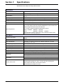
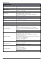


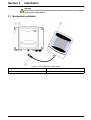

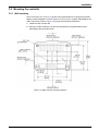

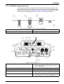

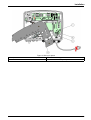
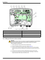

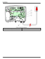
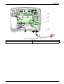
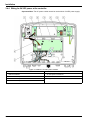


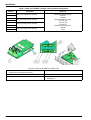


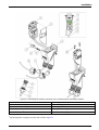
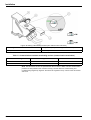


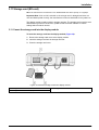


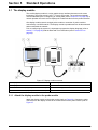
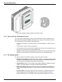


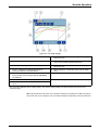
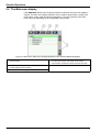
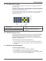


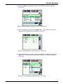


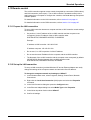


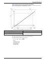


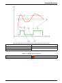


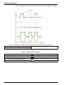

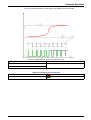

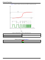
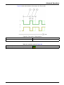

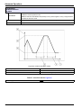


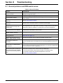

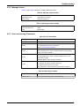


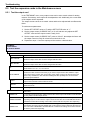


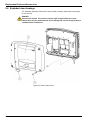

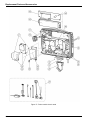
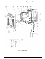


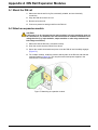
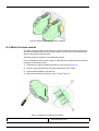


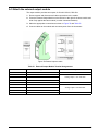


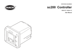
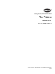
![[U7.03.12] Opérateur CALC_MISS](http://vs1.manualzilla.com/store/data/006373357_1-eb094028fe95faeaac67ba9fcdd78e56-150x150.png)