Transcript
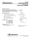
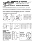
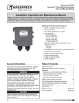
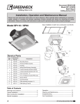
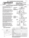
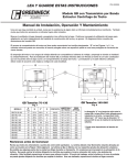
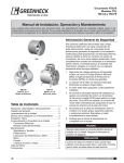
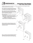
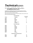
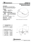
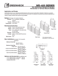
Part Number 452723
End Switch Kit
For use on WD series Dampers
Field Installation Instructions
1. Position end switch such that the back side of damper blade trips
the spring rod.
2. Mount end switch bracket to damper frame or ductwork using
#10 x 1⁄2 in. self-drilling sheet metal screws
End switches are typically wired to a fan
and/or to a light serving as an open/not open
indicator. When the damper is powered open,
one of the damper blades makes contact with
the spring rod of the end switch which in turn
makes a connection allowing power to flow to
the fan and/or light. This set up would be used
when it is desirable to ensure that the damper
is fully open before the fan starts.
Part #
Qty.
1
1
End switch mounting bracket
2
1
End switch
UL/CSA Rating L67
15 Amps: 125, 250, or 480 VAC
0.25 Amps: 250 VDC
0.50 Amps: 125 VDC
3
Damper Frame
Damper
Tie Bar
2
1⁄2
in.-14 NPSM
Description
3
3
2
#6-32NC x 11/2 in. machine screws with
nuts (packaged in end switch housing)
4
2
#10 x 1/2 in. self-drilling sheet metal
screws
1
Spring Rod
Damper
Blade
4
End Switch Installation On
WD-100 Series Dampers
Damper Frame
3
Damper Frame
Damper
Blade
Fan or
Light
r
amper
lade
Instructions:
These instructions apply to the field
installation of end switch kits on Greenheck
model WD Backdraft Dampers. These end
switch kits can be used in conjunction
with MP-100, MP-200, and MP-300 Series
actuators.
2
1⁄2
in.-14 NPSM
L1
L2
Common
4
3
N.C.
End
Switch
Damper
Tie Bar
3
N.O.
M
Green
1
Damper
Actuator
Spring Rod
Wiring Illustration
Note: Some actuators are multi-tap,
use correct connections per
actuator wiring diagram.
4
Wiring Illustration
Spring Rod
1
3
2
1⁄2
in.-14 NPSM
End Switch Installation On
WD-200 & 300 Series Dampers
Copyright © 2008 Greenheck Fan Corporation
#452723 End Switch Rev 3 Aug 2008