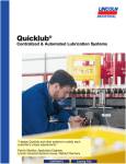
1
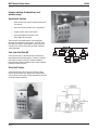
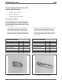
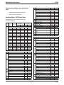
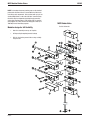
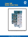
®
Trabon MSP
Modular Divider Valves
Your key to maximum design flexibility with series-progressive reliability.
MSP Modular Divider Valves
Match lubricant flow to the exact needs of
each point.
•
Precise monitoring, positive feedback
•
Simple to install and operate
•
Modular design for total flexibility
The flexible, modular MSP Divider Valve
•
For grease or oil systems up to 3,500 psi (241 bar)
•
Lubricate up to 16 points per valve assembly
•
Choice of SAE, NPSF or BSPP inlet/outlet connections
•
O-Ring sealing prevents leaks, reduces maintenance
•
Individual valve outputs vary by a maximum ratio of
16:1
•
Built-in check valves prevent lube re-entry and help
keep lines full
•
Stackable design simplifies installation, adds flexibility
•
Available in carbon steel with corrosion-resistant
plating. Contact Graco's factory regarding 316
stainless steel for corrosive applications
L10102
Match lubricant flow to the exact needs of
each point.
Each assembly includes: (1) valve sections with working
pistons (3 minimum), (2) subplates with outlet ports, (3) inlet
section, and (4) end sections.
Twin piston sections are ported to create separate outputs for
two lube points. Single sections combine the output from both
ends of the piston and send it to a single lube point.
Field-installable crossport or singling plates (5) may be used
to increase the flow to a single point or accommodate an odd
number of lube points.
A bypass section is available to eliminate a piston section or
provide for added lube points in the future.
NOTE: When bypass sections are used, the Divider Valve
assembly must have a minimum of 3 working sections in
addition to one or more bypass sections.
3
1
5
2
4
Page 2
MSP Modular Divider Valves
Improve matchup of lube delivery and
machine usage.
Special Inlet Sections
•
Allow zoning of large systems served by single pump
and reservoir
•
Choice of inlet port activation: electric or pneumatic
•
Simpler to install, add or remove points
•
Choice of SAE, NPSF, BSPP (ISO 1179) or
metric (ISO 6149) connection
These versatile inlets provide positive, series-progressive
lubrication for extended lines and systems. You easily match
lube delivery to machine usage, bypass machinery that's not
currently in use, and get reliable start-up testing, monitoring,
and fault detection.
Zero-Leak Inlet Shut-Off
A two-way valve that can be used with either continuous or
intermittent pressurized harder systems. Replaces a standard
inlet section or mounts in-line with a remote manifold kit.
Refer to bulletin L10104 for additional details. Refer to bulletin
L10105 for modular zero-leak.
Shunt Inlet Section
A three-function valve, either electric or pneumatic: allows
lubricant to enter divider valve, bypasses it to another divider
valve, or diverts it back to tank. Replace standard inlet or mount
in-line with remote manifold kit.
Page 3
L10102
MSP Modular Divider Valves
L10102
A wide variety of safeguards monitor and
verify lube cycles
•
Track valve-piston action
•
Easily interfaced to system controller
Cycle Indicators
•
Magnetic Visual Indicator: Six steel balls in a
clear sleeve follow a magnet which moves with the
cycling piston, providing a clear visual indication
of lube cycles. Part number: with O-Ring, 563251
(509-932-522).
•
Cycle Indicator Switch (SPDT): Used in conjunction
with the cycle indicator pin at cycle rates not
exceeding 60 cpm, it provides an electrical signal
to the system controller which counts cycles to
monitor and verify completion of the lube cycle.
Part number: 563272 (510-599-000). A moistureresistant switch, 563273 (510-599-200), is also
available.
•
LED Field-sensitive Proximity Switch: This 24 VDC
device magnetically senses the movement of the
piston, triggering the switch and illuminating the LED.
Part numbers: 3-pin with O-Ring, 563478 (527-005690); 5-pin with O-Ring, 563477 (527-005-670);
Explosion proof with O-Ring; 563485 (527-006-060).
•
Connecting Cables: Brad Harrison mating cables
with either 3- or 5-pin connectors are available in 12ft. (3.65 m) lengths for the F/S proximity switches and
other devices. Refer to bulletin 15600 for complete
listing of proximity cycle switches.
These mechanical and electrical units sense the divider valve
piston’s action for accurate control and monitoring of lube
cycles.
•
Cycle Indicator Pin: Valve sections are available with
a factory-installed indicator pin which moves in and
out as lubricant passes through the valve.
•
Universal Cycle Counter: Six-digit counter displays
each complete cycle of the divider valve. Requires
divider valve section with indicator pin (described
above). Part number: 563444 (527-002-410).
•
Field-sensitive Proximity Switch: A ceramic-magnet
switch for grease or oil systems up to 200 cpm at
pressure up to 3,500 psi (241 bar), accurately signals
piston cycles, and is ideal for high-cycle applications.
Part numbers: 3-pin with O-Ring, 557741 (527-003251); 5-pin with O-Ring, 557746 (527-004-111).
Page 4
MSP Modular Divider Valves
L10102
Choice of indicators offer automatic system
protection and fault location.
•
Immediate response to blockages
•
Manual or automatic reset
•
Continues to serve unaffected points
Performance Indicators
These vital safeguards react to excess lube pressure when
points or lines become blocked. Installed in indicator ports on
the working piston sections, they quickly identify the affected
lines. Refer to bulletin L15401 for complete listing of available
performance indicators.
•
Automatic Relief-to-Atmosphere Indicator (O-Ring Seal):
Spring-loaded piston unseats when blockage occurs,
venting lubricant to atmosphere each time piston cycles.
This allows system to lubricate unaffected points. When
the blockage is cleared, the indicator resets automatically.
ORDERING INFORMATION
•
Manual Reset Indicator with Memory (O-Ring Seal): System
blockage triggers a spring-loaded piston to display an
indicator. Since there is no relief, pressure backs up in
the system and the system stops, allowing a controller to
alarm. After correcting the problem, the indicator pin is
reset manually.
ORDERING INFORMATION
Description
Part No.
Old Part No.
Description
Part No.
Old Part No.
O-Ring, 750 psi (51 bar)
563170
508-310-415
O-Ring, 250 psi (17 bar)
563252
509-932-590
O-Ring, 1000 psi (69 bar)
563171
508-310-425
O-Ring, 500 psi (34 bar)
563253
509-932-600
O-Ring, 1250 psi (86 bar)
563172
508-310-435
O-Ring, 750 psi (51 bar)
563254
509-932-610
O-Ring, 1500 psi (103 bar)
563173
508-310-445
O-Ring, 1000 psi (69 bar)
563255
509-932-620
O-Ring, 2000 psi (138 bar)
563174
508-310-455
O-Ring, 1500 psi (103 bar)
563256
509-932-630
O-Ring, 2500 psi (172 bar)
563175
508-310-465
O-Ring, 2000 psi (138 bar)
563257
509-932-640
O-Ring, 3000 psi (207 bar)
563176
508-310-475
O-Ring, 2500 psi (172 bar)
563258
509-932-650
Automatic Relief-to-Atmosphere Indicator
Page 5
Manual Reset Indicator with Memory
MSP Modular Divider Valves
L10102
Designed with over 100 years of experience in
centralized lubrication.
•
Engineering certified to ISO 9001 Standards
•
Modular design for maximum flexibility
•
Install and maintain without disturbing lube lines
MSP DIVIDER SPECIFICATIONS
Standard Material
Corrosion Protected Steel
Optional Material
Type 316 Stainless Steel
O-Ring Seals
Standard - 70 Durometer Buna-N
Optional - 70 Durometer Viton
Quality Design
Max Cycle Rate:
w/Cycle Pin
60 CPM
w/out Cycle Pin, or w/Prox
Cycle Sw
200 CPM
Pressure (max)
3500 psi (241 bar)
Temperature (max)
Buna-N Seals - 200ºF (93ºC)
Lubricant
Oil or Grease
Viton Seals - 350ºF (177ºC)
Zero Leak Inlet:
TOP VIEW
Pressure (max)
1500 psi (104 bar)
Ambient Temperature (max)
140ºF (60ºC)
Lubricant (oil only)
up to 5000 SUS
Requires 25 micron (min) filtration
Electrical Characteristics
See page 7
Shunt/Shut-Off Inlet:
Pressure (max)
3000 psi (207 bar)
Intermittent supply pressure only
SIDE VIEW
Ambient Temperature (max)
140ºF (60ºC)
Lubricant
Oil and Fluid Grease
Filter oil through 25 micron filter
and grease through a 100 mesh
strainer
FRONT VIEW
Electrical Characteristics
See page 7
DIVIDER VALVE ASSEMBLY
Style
Tab(s)
CR Right
Description
Net Weight lbs (kg)
3 section
5.9 (2.7)
4 section
7.3 (3.3)
5 section
8.7 (4.0)
6 section
10.2 (4.6)
7 section
11.6 (5.6)
8 section
13.0 (5.9)
"A"
Right
Qty of
Sections
CL Left
Left
3
3.578 (90.881)
CB-Both
Right & Left
4
4.500 (114.30)
Singling
None
5
5.422 (137.718)
TORQUE SPECIFICATIONS
6
6.344 (161.138)
TIe Rod Nut
5-8 ft lbs
7
7.266 (184.556)
Valve Block Mtg. Screw
8-9 ft lbs*
8
8.188 (207.975)
Indicator Port Plug
8-9 ft lbs*
Inlet Bleed Screw
1-2 ft lbs
Piston Enclosure Plug
12-15 ft lbs*
*O-Ring sealed components
Page 6
MSP Modular Divider Valves
Zero-Leak Inlet Shut-Off Valve
L10102
Shunt Inlet Option
“A”
(See Page 6)
Zero-Leak Electrical Specifications:
Shunt/Shut-Off Electrical Specifications:
115 VAC, 0.22 A In-Rush, 0.14 A Holding 24 VDC, 28 W
115 VAC, 1.6 A In-Rush, 0.54 A Holding 24 VDC, 28 W
Solenoid mounted on right side n.o. to divider, closed to bypass
Solenoid mounted on left side n.c. to divider, open to bypass
Page 7
MSP Modular Divider Valves
L10102
You can easily configure the system to the
need.
•
Item
8
Custom performance from stock modules
•
Choice of Single or Twin outlets
Specifying Guide - MSP Divider Valve
1
Item
Part No.
Old Part No.
3 Section
557731
527-001-930
4 Section
557732
527-001-940
5 Section
557733
527-001-950
6 Section
557734
527-001-960
7 Section
557735
527-001-970
8 Section
557736
527-001-980
9
Tie Rod Nut Only (3 required)
556371
410-440-010
10
Valve Block Mounting Screws
556513
419-140-070
11
Piston Enclosure Plug
557716
527-000-232
12
Piston Enclosure O-Ring
556568
422-210-040
13
Indicator Port Plug
557776
527-300-840
Valve Sections
14
Indicator Port Plug O-Ring
556567
422-210-030
5T - .005
0.005 (0.082)
562720
106-100-175
15
MSP Buna-N O-Rings
556540
422-010-060
5S - .005
0.010 (0.164)
562711
106-100-015
Component Identification and Ordering Information*
Zinc plated carbon steel
Item
Description
Tie Rod (3 required)
Description
T = Twin
S = Single
Displacement
in3 (cm3)
Buna-N Seal
Part no.
Old Part No.
w/Cycle Pin (RH)
Buna-N Seal
Part No.
Old Part No.
10T - .010
0.010 (0.164)
562721
106-100-185
10S - .010
0.020 (0.328)
562712
106-100-025
15T - .015
0.015 (0.246)
562722
106-100-195
15S - .015
0.030 (0.492)
562713
106-100-035
20T - .020
0.020 (0.328)
562723
106-100-205
562739
106-100-935
20S - .020
0.040 (0.656)
562714
106-100-045
562729
106-100-735
25T - .025
0.025 (0.410)
562724
106-100-215
562740
106-100-945
25S - .025
0.050 (0.820)
562715
106-100-055
562730
106-100-745
30T - .030
0.030 (0.492)
562725
106-100-225
562741
106-100-955
30S - .030
0.060 (0.983)
562716
106-100-065
562731
106-100-755
35T - .035
0.035 (0.574)
562726
106-100-235
562742
106-100-965
35S - .035
0.070 (1.148)
562717
106-100-075
562732
106-100-765
40T - .040
0.040 (0.656)
562727
106-100-245
562743
106-100-975
40S - .040
0.080 (1.311)
562718
106-100-085
562733
106-100-775
557721
527-000-810
Valve Block Mounting Screw for Crossport/Singling
Plate
556514
419-140-080
17
Outlet Check Ball
556327
401-030-020
18
Outlet Check Spring
557737
527-001-910
Part No.
Old Part No.
Special Inlets
Valve
State
Description
Zero-Leak, 115 VAC, 3-Pin Brad Harrison Connector
N.C.
1/4-18 NPSF
563460
527-004-320
N.C.
9/16-18 SAE
563468
527-005-200
Replacement Coil
557226
492-120-206
Zero-Leak, 24 VDC, 3-Pin Brad Harrison Connector
N.C.
1/4-18 NPSF
563464
527-004-870
N.C.
9/16-18 SAE
563467
527-005-180
N.C.
1/4 BSPP (ISO 1179)
563082
463-920-720
Replacement Coil
557225
492-120-205
Zero-Leak, No Coil (order separate)
563462
527-004-770
Part No.
Old Part No.
1/8-27 NPSF
563425
527-000-311
7/16-20 SAE
563451
527-003-550
N.O.
1/4-18 NPSF
563452
527-003-660
1/8-28 BSPP (ISO 1179)
563447
527-003-140
N.O.
9/16-18 SAE
560953
527-004-790
N.C.
1/4-18 NPSF
563453
527-003-670
1/4-18 NPSF
560919
527-001-800
N.C.
9/16-18 SAE
563463
527-004-800
7/16-20 SAE
560943
527-003-540
Replacement Coil
557214
492-120-128
1/4-19 BSPP (ISO 1179)
560936
527-003-130
Shunt/Shut-Off, 24 VDC, 3-Pin Brad Harrison Connector
N.O.
1/4-18 NPSF
563454
527-003-680
1/4-18 NPSF
563420
527-000-321
N.O.
9/16-18 SAE
563482
527-005-780
7/16-20 SAE
563422
527-000-325
N.O.
1/4 BSPP (ISO 1179)
563493
527-007-090
4
End Section
563424
527-001-900
N.C.
1/4-18 NPSF
563455
527-003-690
†
End (SPP)
563279
510-770-332
N.C.
9/16-18 SAE
563483
527-005-785
5
Crossport Plate
N.C.
1/4 BSPP (ISO 1179)
563494
527-007-100
2
3
Description
MSP (70 Duro) Viton O-Ring
16
Subplate
Inlet
Inlet w/Bleed
Shunt/Shut-Off, 115 VAC, 3-Pin Brad Harrison Connector
Right
563469
527-005-320
Replacement Solenoid
557215
492-120-130
Left
563470
527-005-330
Shunt/Shut-Off Pneumatic Operator
563456
527-003-730
Both
563471
527-005-340
Remote Manifold kit - Zero-Leak and Shunt/Shut-Off
6
Singling Plate
563472
527-005-350
1/4-18 NPSF
563461
527-004-360
7
Bypass Block
562660
106-000-010
9/16-18 SAE
–
527-005-400
Page 8
MSP Modular Divider Valves
NOTE: Part numbers shown on previous page are for standard
plated steel with Buna-N Seals. Consult Graco for Viton Seals
or stainless steel components. Valve sections with cycle pin are
standard Right Hand; can be made Left Hand. Consult factory.
Consult factory for components requiring thread connection
series other than those listed. † End Section (SPP) is supplied
with plugged 1/8-27 NPS manual lube fitting port. Order (412700-490) manual lube fitting separate.
Modular design for full flexibility
•
One valve assembly serves up to 16 points
•
O-Ring sealing throughout prevents leakage
•
Built-in check valves prevent lube re-entry and help
keep lines full
Page 9
L10102
MSP Divider Valve
Part List Schematic
MSP Modular Divider Valves
How to Order
Ordering Information
L10102
Notes
XXX - XXX - XX - X
-
X - XX - X - XX
1.
Right/Left Hand determined when
viewing front of divider valve
assembly. (Divider valve assembly
placed on flat surface with inlet at
top.)
2.
Valves are specified starting from
inlet section.
3.
When valve is crossported, its outlet
is plugged and output is diverted to
next valve away from inlet.
4.
Last valve in divider assembly,
farthest from inlet, cannot be
crossported.
5.
Single valve can be crossported on
one side only.
6.
When valve is a single, only one
outlet in its subplate can be used,
other outlet must be plugged.
NUMBER OF SECTIONS
7.
3 - THREE
4 - FOUR
5 - FIVE
Cycle pins are available on MS (20,
25, 30, 35, and 40) valves only.
8.
All divider valve assemblies must
have a minimum of 3 working
valves.
9.
Bypass block cannot be supplied
on divider valve with 3 subplates.
Bypass block is not a working valve.
SERIES OF FEEDER
MSP - STANDARD INDUSTRIAL TO 3500 PSI
MSV - SYNTHETIC INDUSTRIAL TO 3500 PSI
(VITON SEALS)
INLET/OUTLET PORT TYPES
SAE - STRAIGHT THREAD O-Ring SEAL
NPT - NPSF PIPE THREAD
BPS - BRITISH PARALLEL PIPE O-Ring SEAL (LSO 1179)
MET - METRIC THREAD O-Ring (ISO 6149)
INLET SECTION OPTIONS
MS - MS DIVIDER INLET
MH - MS DIVIDER INLET W/BLEED SCREWS
SH - MS DIVIDER W/SHUNT/SHUT-OFF (115 VAC)
SD - MS DIVIDER W/SHUNT/SHUT-OFF (24 VDC)
ZL - ZERO LEAK SHUT-OF (115 VAC)
ZF - ZERO LEAK SHUT-OFF (24 VDC)
DIVIDER VALVE ACCESSORY OPTIONS
P - ASSEMBLY OF PERFORMANCE INDICATORS IN ALL WORKING OUTLETS
B - ASSEMBLY OF PERFORMANCE INDICATORS AND CHECK VALVES IN ALL
WORKING OUTLETS
C - EXTERNAL CHECK VALVES IN ALL WORKING OUTLETS
E - SPP END SECTION W/PLUG IN 1/8-27 NPSF PORT FOR MANUAL LUBE FITTING 563279 - (510-770-332)
6 - SIX
7 - SEVEN
8 - EIGHT
VALVE CAPACITY MS VALVE BLOCK
BP - BYPASS
05 - .005 cu.in. (.082 cm3)
10 - .010 cu.in. (.164 cm3)
15 - .015 cu.in. (.246 cm3)
20 - .020 cu.in. (.328 cm3)
25 - .025 cu.in. (.410 cm3)
30 - .030 cu.in. (492 cm3)
35 - .035 cu.in. (.574 cm3)
40 - .040 cu.in. (.656 cm3)
TYPE OF VALVE BLOCK
T - TWIN VALVE
S - SINGLE VALVE - RH OUTLET
L - SINGLE VALVE - LH OUTLET
B - TWIN VALE W/CYCLE PIN RIGHT
C - SINGLE VALVE W/CYCLE PIN RIGHT - RH OUTLET
D - SINGLE VALVE W/CYCLE PIN RIGHT - LH OUTLET
H - TWIN VALVE W/CYCLE PIN LEFT
J - SINGLE VALVE W/CYCLE PIN LEFT - RH OUTLET
K - SINGLE VALVE W/CYCLE PIN LEFT - LH OUTLET
10. Divider systems should be limited to
first and second stages only. Third
staging is not recommended. Refer
to Trabon Bulletins L20101, L20105
and L20115 for further information
on system design.
CROSSPORTING OPTION
Caution
CR - RIGHT HAND SIDE
CL - LEFT HAND SIDE
CB - BOTH SIDES
Ordering Example
5-section MSP Divider Valve Assembly, standard seals, SAE ports and
performance indicators in each working outlet. Consisting of:
1 - .030 Twin Valve with Cycle Pin Right Side
1 - .040 Single Valve - Crossport Right Side
1 - .040 Single Valve - Right Hand Outlet
1 - .020 Twin Valve
1 - Bypass Block
Ordering Code - MSP-SAE-MS-P-5-30B-40SCR-40S-20T-BP
BY P
Page 10
MSP Modular Divider Valves
L10102
Graco® has applied automatic lubrication
technology to a world of needs including
yours!
Automated systems improve safety. Maintenance personnel do
not have to lubricate dangerous machinery. Operators have less
exposure to oil and lubricants on equipment and floor.
Graco systems require minimum attention. Filling the reservoir
and periodic inspections are the only routine maintenance
required.
Graco's precise lubricant delivery eliminate lubricant waste,
product contamination and heat buildup from excessive viscous
shear.
Lube delivery to machines in motion is ofter superior to static
lubrication. Oil and grease are forced into the load area to coat
wear points.
Surges, vibrations, and other erratic operations are reduced
with automatic lube systems. This minimizes risk of damage to
equipment, products and personnel.
Graco's automated systems deliver lubricant to vital
mechanisms, prolonging equipment life and reducing downtime.
Page 11
All Graco systems are engineered for the machinery and
lubricant being used. We can even supply the lubricant,
matched to the system you need.
Your solution is at hand.
Our years of engineering innovative lubrication
technology, plus our worldwide network of more than
100 distributors means that the components you
need are probably in stock right now. This inventory
of proven components allows distributors and factory
engineers to design a truly customized system using
economical on-the-shelf parts.
New or upgrade, Graco has the applied
technology.
Whether you are considering new equipment or
upgrading an existing system, count on Graco for
the applied lubrication technology to meet your need
with a minimum of hassle and investment. Call on
our unparalleled customer support for fast, efficient
design, installation, maintenance and troubleshooting
assistance, or to get the name of your nearest full-line,
factory-trained distributor.
All written and visual data contained in this document are based on the latest product information available at the time of publication. Graco reserves the right to make changes at any time without notice.
Contact us today!
To receive product information or talk with a Graco representative,
call 800-533-9655 or visit us online at www.graco.com.
©2005-2008 Graco Inc. Form No. L10102 Rev. B 7/09 Printed in U.S.A. All other brand names or marks are used for identification purposes and are trademarks of their respective owners. All written and
visual data contained in this document are based on the latest product information available at the time of publication. Graco reserves the right to make changes at any time without notice.